EP0803401B1 - Apparatus for automatically controlling a direction of an optical axis of a vehicle headlight - Google Patents
Apparatus for automatically controlling a direction of an optical axis of a vehicle headlight Download PDFInfo
- Publication number
- EP0803401B1 EP0803401B1 EP97106477A EP97106477A EP0803401B1 EP 0803401 B1 EP0803401 B1 EP 0803401B1 EP 97106477 A EP97106477 A EP 97106477A EP 97106477 A EP97106477 A EP 97106477A EP 0803401 B1 EP0803401 B1 EP 0803401B1
- Authority
- EP
- European Patent Office
- Prior art keywords
- vehicle
- state
- height
- optical axis
- detecting means
- Prior art date
- Legal status (The legal status is an assumption and is not a legal conclusion. Google has not performed a legal analysis and makes no representation as to the accuracy of the status listed.)
- Expired - Lifetime
Links
Images


Classifications
-
- B—PERFORMING OPERATIONS; TRANSPORTING
- B60—VEHICLES IN GENERAL
- B60Q—ARRANGEMENT OF SIGNALLING OR LIGHTING DEVICES, THE MOUNTING OR SUPPORTING THEREOF OR CIRCUITS THEREFOR, FOR VEHICLES IN GENERAL
- B60Q1/00—Arrangement of optical signalling or lighting devices, the mounting or supporting thereof or circuits therefor
- B60Q1/02—Arrangement of optical signalling or lighting devices, the mounting or supporting thereof or circuits therefor the devices being primarily intended to illuminate the way ahead or to illuminate other areas of way or environments
- B60Q1/04—Arrangement of optical signalling or lighting devices, the mounting or supporting thereof or circuits therefor the devices being primarily intended to illuminate the way ahead or to illuminate other areas of way or environments the devices being headlights
- B60Q1/06—Arrangement of optical signalling or lighting devices, the mounting or supporting thereof or circuits therefor the devices being primarily intended to illuminate the way ahead or to illuminate other areas of way or environments the devices being headlights adjustable, e.g. remotely-controlled from inside vehicle
- B60Q1/08—Arrangement of optical signalling or lighting devices, the mounting or supporting thereof or circuits therefor the devices being primarily intended to illuminate the way ahead or to illuminate other areas of way or environments the devices being headlights adjustable, e.g. remotely-controlled from inside vehicle automatically
- B60Q1/10—Arrangement of optical signalling or lighting devices, the mounting or supporting thereof or circuits therefor the devices being primarily intended to illuminate the way ahead or to illuminate other areas of way or environments the devices being headlights adjustable, e.g. remotely-controlled from inside vehicle automatically due to vehicle inclination, e.g. due to load distribution
- B60Q1/115—Arrangement of optical signalling or lighting devices, the mounting or supporting thereof or circuits therefor the devices being primarily intended to illuminate the way ahead or to illuminate other areas of way or environments the devices being headlights adjustable, e.g. remotely-controlled from inside vehicle automatically due to vehicle inclination, e.g. due to load distribution by electric means
-
- B—PERFORMING OPERATIONS; TRANSPORTING
- B60—VEHICLES IN GENERAL
- B60Q—ARRANGEMENT OF SIGNALLING OR LIGHTING DEVICES, THE MOUNTING OR SUPPORTING THEREOF OR CIRCUITS THEREFOR, FOR VEHICLES IN GENERAL
- B60Q2300/00—Indexing codes for automatically adjustable headlamps or automatically dimmable headlamps
- B60Q2300/10—Indexing codes relating to particular vehicle conditions
- B60Q2300/11—Linear movements of the vehicle
- B60Q2300/114—Vehicle acceleration or deceleration
-
- B—PERFORMING OPERATIONS; TRANSPORTING
- B60—VEHICLES IN GENERAL
- B60Q—ARRANGEMENT OF SIGNALLING OR LIGHTING DEVICES, THE MOUNTING OR SUPPORTING THEREOF OR CIRCUITS THEREFOR, FOR VEHICLES IN GENERAL
- B60Q2300/00—Indexing codes for automatically adjustable headlamps or automatically dimmable headlamps
- B60Q2300/10—Indexing codes relating to particular vehicle conditions
- B60Q2300/11—Linear movements of the vehicle
- B60Q2300/116—Vehicle at a stop
-
- B—PERFORMING OPERATIONS; TRANSPORTING
- B60—VEHICLES IN GENERAL
- B60Q—ARRANGEMENT OF SIGNALLING OR LIGHTING DEVICES, THE MOUNTING OR SUPPORTING THEREOF OR CIRCUITS THEREFOR, FOR VEHICLES IN GENERAL
- B60Q2300/00—Indexing codes for automatically adjustable headlamps or automatically dimmable headlamps
- B60Q2300/10—Indexing codes relating to particular vehicle conditions
- B60Q2300/13—Attitude of the vehicle body
- B60Q2300/132—Pitch
Definitions
- the present invention relates to an apparatus for automatically controlling a direction of an optical axis of a vehicle headlight.
- a vehicle headlight has been required to control a direction of an optical axis of the headlight, because illumination of the headlight dazzles a driver driving a vehicle facing the headlight for a moment if the direction of the optical axis turns upward due to an inclination of the vehicle, or the faraway visibility may be poor if the direction of the optical axis turns downward due to a declination of the vehicle.
- Apparatuses that solve this problem are disclosed in JP-A-5-229383, JP-A-5-250901, and JP-A-6-32169; however, these apparatuses are complex and expensive.
- a control apparatus of said type which comprises at least one sensor for detecting a pitch angle of a vehicle wherein the optical axis of the vehicle is controlled by filtering the respectively detected pitch angle by using a low-pass filter.
- This low-pass filter is able to change a frequency interruption characteristic which depends on. the amplitude of the pitch angle signal. If the amplitude is lower than a threshold value corresponding to the acceleration/deceleration, the frequency interruption characteristic becomes 0.15 hertz; on the other hand, if the amplitude is higher than this threshold value the frequency interruption characteristic is in the range of 1 and 2 hertz.
- this known apparatus removes a high frequency component which goes back to the roughness of the road, thereby preventing any deviation of the optical axis by controlling the pitch angle which is caused by the acceleration/deceleration of the vehicle.
- This known control apparatus also needs plural height sensors in order to be able to control the direction of the optical axis.
- the object of the present invention is to provide a simple and inexpensive apparatus for automatically controlling a direction of an optical axis of a vehicle headlight, and especially to provide an apparatus which automatically controls a direction of an optical axis of the vehicle headlight based on outputs from a single height sensor disposed in the vehicle.
- a first vertical displacement at one longitudinal side of a vehicle is outputted from a single height detecting device, and a second vertical displacement at the other longitudinal side of the vehicle is estimated based on the first vertical displacement outputted from the single height detecting device; thus, the inclination is calculated based on the second vertical displacement at the other longitudinal side of the vehicle and the first vertical displacement outputted from the single height detecting device; therefore the inclination is nearly the same as an inclination calculated by an apparatus which has multiple sensors. Therefore, the apparatus according to the present invention can properly control the direction of the optical axis of the headlight without needing multiple height sensors in the vehicle.
- FIG. 1 is a schematic view illustrating an apparatus for automatically controlling a direction of an optical axis of a vehicle headlight according to a first preferred embodiment of the present invention.
- a height sensor 11 is disposed between a rear axle and a body of a vehicle, and a throttle opening degree sensor (throttle angle sensor) 12, a vehicle speed sensor 13, and other sensors (not shown) are also disposed in the vehicle.
- This height sensor 11 outputs a rear height signal HR (height displacement at a side of the vehicle rear wheels) as relative height displacement between the rear axle and the body
- the throttle opening degree sensor 12 outputs a throttle opening degree signal (throttle angle signal) TA
- the vehicle speed sensor 13 outputs a vehicle speed signal VSP.
- Sensor signals for instance, the rear height signal HR, the throttle opening degree signal TA, and the vehicle speed signal VSP outputted from the sensors are inputted to an ECU (Electronic Control Unit) 20 disposed in the vehicle.
- the ECU 20 is illustrated out of the vehicle as shown in FIG. 1 for convenience, as are the throttle opening degree sensor 12 and the vehicle speed sensor 13.
- the ECU 20 includes a CPU 21 as a central processing unit, ROM 22 storing a processing program, RAM 23 for recording several data, B/U (Back Up) RAM 24, I/O interface 25, and bus line 26 connecting all of them together.
- Output signals from ECU 20 are inputted to an actuator 35 disposed next to a vehicle headlight 30, and a direction of an optical axis of the vehicle headlight 30 is controlled as described later.
- Sensor signals outputted from sensors, for instance, the throttle opening degree sensor 12 and the vehicle speed sensor 13, are used to determine the state of the vehicle, for instance, running state, stopped state, accelerating state, and decelerating state. There are four wheels on the vehicle, two of which are shown in FIG. 1.
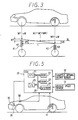
- FIG. 2 is a schematic view illustrating a basic structure of the headlight 30.
- the headlight 30 includes a lamp 31, a reflector 32 which fixes the lamp 31 in place, supporting part 33 which supports an upper part of the reflector 32 so that the reflector 32 can swing in the direction shown by the arrow illustrated as a circular arc, movable part 34 which supports the lower part of the reflector 32, and actuator 35, for instance a step motor, which shifts the movable part 34 in the direction shown by the arrow illustrated as a straight line.
- the direction of the optical axis of the headlight 30 is previously set up to provide optimum illumination for the vehicle's drivers.
- FIG. 3 is a schematic diagram illustrating a position of a body and a suspension of the vehicle under acceleration.
- a front suspension 41 disposed at a end of the vehicle front wheels extends upwardly and a rear suspension 42 disposed at the side of the vehicle rear wheels compresses because a load of the vehicle moves to the back of the vehicle.
- front height HF height displacement at a side of the vehicle front wheels
- Equation (1) KF is the spring constant of the front suspension 41, and KR is the spring constant of the rear suspension 42.
- ⁇ W HR ⁇ KR ⁇ 2 Because there are a right rear wheel and a left rear wheel in the vehicle, " ⁇ 2" is needed in above equation.
- the load movement toward the front wheel is the same as the load movement toward the rear wheel ⁇ W except for the sign of the above load movement ⁇ W, and the sign is opposite because the load moves to the back of the vehicle in this state, so the front height HF is calculated by the following Equation (2).
- a pitch angle ⁇ 1 as an inclination with respect to the reference plane previously set and extending across the vehicle is calculated by the following Equation (3), where L is a distance between the front axle and the rear axle.
- ⁇ 1 tan -1 ⁇ (HF - HR) / L ⁇
- distance and angles above the reference plane will be deemed to have positive polarity, while distance and angles below the reference plane will be deemed to have negative polarity.
- distances HF and HR will always have opposite signs.
- a control angle for the direction of the optical axis ⁇ 2 such that illumination of the headlight 30 does not dazzle a driver driving another vehicle facing the headlight 30 is nearly the same as the pitch angle ⁇ 1, and the sign of angle is opposite to that of ⁇ 1 because the load moves to back of the vehicle, so the actuator 35 is operated and the direction of the optical axis of the headlight 30 is controlled based on the angle ⁇ 2.
- the front height HF is estimated by the following Equation (4), based on the rear height signal HR.
- Equation (4) based on the rear height signal HR.
- ⁇ is a correction coefficient in the range of 0 to ⁇ 2, which depends on the rigidity of the front suspension 41. For instance, when ⁇ is zero, the front height HF is regarded as having no displacement.
- the pitch angle ⁇ 1 and the control angle for the direction of the optical axis ⁇ 2 can be calculated in the same manner as above.
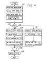
- FIG. 4 is a flowchart of processing in the CPU 21 disposed in the ECU 20 according to the first embodiment.
- Step S101 reads sensor signals, for instance, the throttle opening degree signal TA, the vehicle speed signal VSP, and the rear height signal HR.
- Step S102 determines whether or not the vehicle speed signal VSP read by Step S101 is zero. If Step S102 determines the vehicle speed signal VSP is not zero, the vehicle should be in the running state, so Step S103 calculates the pitch angle ⁇ 1 based on Equations (1) -(3).
- Step S102 determines the vehicle speed signal VSP is zero, the vehicle should be in the stopped state, so Step S104 calculates the pitch angle ⁇ 1 based on Equations (3) and (4).
- Step S105 calculates the control angle for the direction of the optical axis ⁇ 2.
- Step S106 operates the actuator 35 based on the control angle for the direction of the optical axis ⁇ 2 calculated by Step S105, and then, the direction of the optical axis of headlight 30 is properly controlled responsive to the state of the vehicle (running state and stopped state).
- the way of operating the actuator 35 for instance, controlling speed of the actuator 35, is omitted for brevity.
- the apparatus can properly control the direction of the optical axis of the headlight 30 although there are not multiple height sensors in the vehicle. Furthermore, because the height sensor 11 is disposed between the rear axle and the body of the vehicle, and rear height displacement at the rear side is detected by the height sensor 11, it is easier to detect increase and decrease of passengers and baggage in the vehicle than a case that the height sensor 11 is disposed between the front axle and the body of the vehicle.
- the pitch angle ⁇ 1 is nearly the same as an inclination calculated by an apparatus which has multiple sensors. Because the pitch angle ⁇ 1 is responsive to the state of the vehicle, the control angle for the direction of the optical axis ⁇ 2 can be adapted to the state of the vehicle.
- FIG. 5 is a schematic view illustrating an apparatus for automatically controlling the direction of the optical axis of the vehicle headlight according to a second preferred embodiment of the present invention.
- the structure of the apparatus is the same as in the first embodiment except for an acceleration sensor 50, so the same parts as the apparatus described in the first embodiment are denoted by the same signs as the apparatus described in the first embodiment and repeated description is omitted for brevity.
- an acceleration sensor 50 which detects vertical acceleration of the vehicle is disposed next to the front axle of the vehicle.
- an acceleration signal GF is outputted from the acceleration sensor 50 to the ECU 20.
- FIG. 6 is a flowchart of processing in the CPU 21 disposed in the ECU 20 according to the second embodiment.
- Step S201 reads sensor signals, for instance, the throttle opening degree signal TA, the vehicle speed signal VSP, the acceleration signal GF, and the rear height signal HR.
- Step S202 determines whether or not the vehicle speed signal VSP read by Step S201 is zero. If Step S202 determines the vehicle speed signal VSP is not zero, the vehicle should be in the running state, so Step S203 calculates the front height HF by following Equation (5).
- HF ⁇ GF That is, Step S203 double integrates the acceleration signal GF.
- Step S204 calculates the pitch angle ⁇ 1 based on Equations (2) and (3).
- Step S202 determines the vehicle speed signal VSP is zero, the vehicle should be in the stopped state, so Step 504 calculates the pitch angle ⁇ 1 based on Equations (4) and (3).
- Step S206 calculates the control angle for the direction of the optical axis ⁇ 2.
- Step S207 operates the actuator 35 based on the control angle for the direction of the optical axis ⁇ 2 calculated by Step S206, and then, the direction of the optical axis of headlight 30 is properly controlled responsive to the state of the vehicle as in the first embodiment.
- the acceleration sensor 50 is disposed in the vehicle and because the front height HF which is calculated based on not only the rear height signal HR but also the acceleration signal GF from the acceleration sensor 50 is used for calculating the pitch angle ⁇ 1, the front height HF is calculated more accurately, and the direction of the optical axis of the headlight is controlled more properly.
- the acceleration sensor 50 is previously disposed in the vehicle as a part of another vehicle control apparatus, it is easy to adapt the second embodiment.
- the present invention may be embodied in other specific forms without departing from the spirit or essential characteristics thereof. For instance, it is possible to determine the state of the vehicle based on a state of an internal combustion detected by some sensors including the throttle opening degree sensor 12. It is possible to dispose the height sensor 11 not at the rear side of the vehicle but at the front side of the vehicle. It is possible to determine the state of the vehicle by using the acceleration signal GF, and improve the pitch angle ⁇ 1 based on the determination of the state of the vehicle.
Description
Claims (9)
- An apparatus for automatically controlling a direction of an optical axis of a vehicle headlight (30), said apparatus comprising:height detecting means (11) disposed at one longitudinal side of a vehicle, for detecting a first vertical displacement (HR) of said vehicle at said one longitudinal side;displacement estimating means (S103, S203) for estimating a second vertical displacement (HF) at the other longitudinal side of said vehicle where said height detecting means (11) is not disposed, based on said first vertical displacement (HR) of said vehicle at said one longitudinal side;inclination calculating means (S103-S105, S204-S206) for calculating inclinations (1, 2) against a reference plane extending in a direction of said optical axis of said vehicle headlight based on said first vertical displacement (HR) of said vehicle at said one longitudinal side of said vehicle and said second vertical displacement (HF) of said vehicle at said other longitudinal side of said vehicle; andcontrol means (S106, S207, 35) for controlling said optical axis of said vehicle headlight (30) based on one of said inclinations (2) calculated by said inclination calculating means (S103-S105, S204-S206)wherein said height detecting means (11) consists of a single height sensor.
- An apparatus according to claim 1, wherein said height detecting means (11) is disposed at a rear side of said vehicle.
- An apparatus according to claim 1 or 2, further comprising:state detecting means (S102, S202) for detecting an operational state of said vehicle;wherein said inclination calculating means (S103-S105, S204-S206) is for calculating said inclinations (1, 2) responsive to the operational state of said vehicle detected by said state detecting means (S102, S202).
- An apparatus according to claim 3, wherein said inclination calculating means (S103-S105, S204-S206) is for calculating said inclinations (1, 2) against said reference plane extending in the direction of said optical axis of said vehicle headlight (30) based on said first vertical displacement (HR) of said vehicle at said one longitudinal side and said second vertical displacement (HF) of said vehicle at said other longitudinal side when said state detecting means (S102, S202) detects that said vehicle is in a running state.
- An apparatus according to claim 4, wherein said inclination calculating means (S103-S105, S204-S206) is for calculating said inclinations by the following Equation:
- An apparatus according to claim 5, further comprising:acceleration detecting means (50) disposed at a front side of said vehicle, for detecting the vertical acceleration (GF) of said vehicle;wherein said displacement estimating means (S203) is for estimating said height displacement (HF) at said other longitudinal side based on the detected vertical acceleration (GF) of said vehicle.
- An apparatus according to claim 3, wherein said inclination calculating means (S204-S206) is for calculating said inclinations (1, 2) based on only said vertical displacement (HR) at said rear side of said vehicle when said state detecting means (S102, S202) detects that said vehicle is in a stopped state.
- An apparatus according to any one of claims 3 to 7, further comprising:throttle detecting means (12) for detecting a throttle opening degree (TA) as a state of an internal combustion engine of said vehicle;wherein said state detecting means (S102, S202) is for detecting said state of said vehicle based on the detected state of said internal combustion engine of said vehicle.
- An apparatus according to any one of claims 3 to 7, further comprising:vehicle speed detecting means (13) for detecting the vehicle speed (VSP) of said vehicle;wherein said state detecting means (S102, S202) is for detecting said state of said vehicle based on the detected vehicle speed (VSP).
Applications Claiming Priority (3)
| Application Number | Priority Date | Filing Date | Title |
|---|---|---|---|
| JP9975396 | 1996-04-22 | ||
| JP99753/96 | 1996-04-22 | ||
| JP09975396A JP3384236B2 (en) | 1996-04-22 | 1996-04-22 | Automatic adjustment of headlight optical axis direction for vehicles |
Publications (3)
| Publication Number | Publication Date |
|---|---|
| EP0803401A2 EP0803401A2 (en) | 1997-10-29 |
| EP0803401A3 EP0803401A3 (en) | 1998-08-12 |
| EP0803401B1 true EP0803401B1 (en) | 2001-10-04 |
Family
ID=14255756
Family Applications (1)
| Application Number | Title | Priority Date | Filing Date |
|---|---|---|---|
| EP97106477A Expired - Lifetime EP0803401B1 (en) | 1996-04-22 | 1997-04-18 | Apparatus for automatically controlling a direction of an optical axis of a vehicle headlight |
Country Status (3)
| Country | Link |
|---|---|
| EP (1) | EP0803401B1 (en) |
| JP (1) | JP3384236B2 (en) |
| DE (1) | DE69707047T2 (en) |
Cited By (3)
| Publication number | Priority date | Publication date | Assignee | Title |
|---|---|---|---|---|
| DE102007021674A1 (en) | 2007-05-09 | 2008-11-13 | Volkswagen Ag | Method for controlling the optical axis of a vehicle headlight |
| DE102007021675A1 (en) | 2007-05-09 | 2009-01-15 | Volkswagen Ag | Method for controlling the optical axis of a vehicle headlight |
| DE102006031678B4 (en) * | 2006-07-08 | 2017-07-27 | Hella Kgaa Hueck & Co. | Method and device for determining the road condition for influencing headlight systems |
Families Citing this family (31)
| Publication number | Priority date | Publication date | Assignee | Title |
|---|---|---|---|---|
| JP3820299B2 (en) * | 1997-02-18 | 2006-09-13 | 株式会社小糸製作所 | Irradiation direction control device for vehicular lamp |
| JP3518303B2 (en) * | 1998-01-06 | 2004-04-12 | 日産自動車株式会社 | Vehicle pitch angle calculation device |
| JPH11211455A (en) * | 1998-01-20 | 1999-08-06 | Nissan Motor Co Ltd | Arithmetic device for vehicle pitching angle |
| JPH11208365A (en) * | 1998-01-30 | 1999-08-03 | Nissan Motor Co Ltd | Optical axis of headlight adjusting device for vehicle |
| JP3518309B2 (en) * | 1998-02-02 | 2004-04-12 | 日産自動車株式会社 | Vehicle pitch angle calculation device |
| JPH11321270A (en) * | 1998-05-19 | 1999-11-24 | Unisia Jecs Corp | Vehicle height control device |
| JP3740889B2 (en) * | 1998-06-16 | 2006-02-01 | 株式会社デンソー | Automatic headlamp optical axis adjustment device for vehicles |
| JP4059191B2 (en) * | 1998-06-16 | 2008-03-12 | 株式会社デンソー | Automatic headlamp optical axis adjustment device for vehicles |
| JP3518349B2 (en) * | 1998-07-08 | 2004-04-12 | 日産自動車株式会社 | Pitching angle calculation device |
| JP3847972B2 (en) * | 1998-09-18 | 2006-11-22 | 株式会社小糸製作所 | Auto-leveling device for automotive headlamps |
| JP3849960B2 (en) | 1998-09-29 | 2006-11-22 | 株式会社小糸製作所 | Auto-leveling device for automotive headlamps |
| JP3957422B2 (en) * | 1999-02-10 | 2007-08-15 | スタンレー電気株式会社 | Optical axis adjustment device for vehicle headlamp |
| JP3782602B2 (en) * | 1999-02-15 | 2006-06-07 | 株式会社小糸製作所 | Auto-leveling device for automotive headlamps |
| JP2000318580A (en) * | 1999-05-12 | 2000-11-21 | Kanto Auto Works Ltd | Wiper attack angle measuring method and device |
| JP3931495B2 (en) * | 1999-08-02 | 2007-06-13 | 日産自動車株式会社 | Vehicle pitch angle calculation device |
| JP3721013B2 (en) * | 1999-08-23 | 2005-11-30 | 株式会社小糸製作所 | Auto-leveling device for automotive headlamps |
| JP3782619B2 (en) * | 1999-09-09 | 2006-06-07 | 株式会社小糸製作所 | Auto-leveling device for automotive headlamps |
| JP3782634B2 (en) * | 2000-01-11 | 2006-06-07 | 株式会社小糸製作所 | Auto-leveling device for automotive headlamps |
| DE10055039A1 (en) | 2000-11-07 | 2002-05-08 | Hella Kg Hueck & Co | Procedure for lamp width control of car lighting devices has as measured value for determination of future control setpoint value, operating parameter(s) corrected running ahead in time |
| JP2004168179A (en) * | 2002-11-20 | 2004-06-17 | Koito Mfg Co Ltd | Irradiating direction control device of head lamp for vehicle |
| JP2005067300A (en) * | 2003-08-21 | 2005-03-17 | Denso Corp | Device for automatically adjusting optical axis direction of headlight for vehicle |
| JP4290586B2 (en) * | 2004-02-27 | 2009-07-08 | 三菱電機株式会社 | Lighting device and lighting system |
| JP2004352246A (en) * | 2004-08-25 | 2004-12-16 | Mitsubishi Electric Corp | Vehicle headlight control device |
| JP4499172B2 (en) * | 2008-12-12 | 2010-07-07 | 三菱電機株式会社 | Lighting device |
| JP5372488B2 (en) * | 2008-12-19 | 2013-12-18 | 株式会社小糸製作所 | Auto leveling system for vehicle lamps |
| JP6193928B2 (en) * | 2010-10-26 | 2017-09-06 | 株式会社小糸製作所 | Vehicular lamp control device and vehicle attitude angle information calculation method |
| JP5678873B2 (en) | 2011-11-30 | 2015-03-04 | 株式会社デンソー | Vehicle headlamp control device |
| DE102015208795B4 (en) * | 2015-05-12 | 2019-09-05 | Automotive Lighting Reutlingen Gmbh | Method for operating a headlamp of a motor vehicle and headlights for a motor vehicle |
| KR101858702B1 (en) | 2015-12-30 | 2018-05-16 | 엘지전자 주식회사 | Lamp apparatus for Vehicles |
| JP6787297B2 (en) * | 2017-11-10 | 2020-11-18 | 株式会社Soken | Display control device and display control program |
| JP7063856B2 (en) * | 2019-07-30 | 2022-05-09 | 株式会社Soken | Display control device |
Citations (1)
| Publication number | Priority date | Publication date | Assignee | Title |
|---|---|---|---|---|
| DE3129891A1 (en) * | 1980-07-31 | 1982-06-09 | Marchal Equip Auto | Device for the dynamic adjustment of the position of headlamps of a vehicle |
Family Cites Families (4)
| Publication number | Priority date | Publication date | Assignee | Title |
|---|---|---|---|---|
| FR2297153A1 (en) * | 1975-01-10 | 1976-08-06 | Cibie Projecteurs | Device for adjusting vehicle headlamps with vehicle loading - has adjustment motor controlled by strain gauge responsive to loading |
| FR2339513A1 (en) * | 1976-01-30 | 1977-08-26 | Poisson Bernard | Vehicle headlamp inclination regulator - has sleeved cable between rear suspension and lug on lamp to give load responsive control |
| DE4005812C1 (en) * | 1990-02-23 | 1991-04-18 | Siemens Ag, 1000 Berlin Und 8000 Muenchen, De | Motor vehicle suspension level regulator - has sensor assigned to rear axle and sensor in passenger compartment producing load signal with control unit evaluating signals |
| DE4105716A1 (en) * | 1991-02-25 | 1992-08-27 | Audi Ag | Road-speed sensitive vehicular headlamp adjustment appts. - is based on servo-mechanism responsive to rear-wheel loading, only when vehicle is not in motion |
-
1996
- 1996-04-22 JP JP09975396A patent/JP3384236B2/en not_active Expired - Lifetime
-
1997
- 1997-04-18 DE DE1997607047 patent/DE69707047T2/en not_active Expired - Lifetime
- 1997-04-18 EP EP97106477A patent/EP0803401B1/en not_active Expired - Lifetime
Patent Citations (1)
| Publication number | Priority date | Publication date | Assignee | Title |
|---|---|---|---|---|
| DE3129891A1 (en) * | 1980-07-31 | 1982-06-09 | Marchal Equip Auto | Device for the dynamic adjustment of the position of headlamps of a vehicle |
Cited By (4)
| Publication number | Priority date | Publication date | Assignee | Title |
|---|---|---|---|---|
| DE102006031678B4 (en) * | 2006-07-08 | 2017-07-27 | Hella Kgaa Hueck & Co. | Method and device for determining the road condition for influencing headlight systems |
| DE102007021674A1 (en) | 2007-05-09 | 2008-11-13 | Volkswagen Ag | Method for controlling the optical axis of a vehicle headlight |
| DE102007021675A1 (en) | 2007-05-09 | 2009-01-15 | Volkswagen Ag | Method for controlling the optical axis of a vehicle headlight |
| DE102007021674B4 (en) | 2007-05-09 | 2018-07-12 | Volkswagen Ag | Method for controlling the optical axis of a vehicle headlight |
Also Published As
| Publication number | Publication date |
|---|---|
| DE69707047D1 (en) | 2001-11-08 |
| JP3384236B2 (en) | 2003-03-10 |
| JPH09286274A (en) | 1997-11-04 |
| DE69707047T2 (en) | 2002-06-20 |
| EP0803401A2 (en) | 1997-10-29 |
| EP0803401A3 (en) | 1998-08-12 |
Similar Documents
| Publication | Publication Date | Title |
|---|---|---|
| EP0803401B1 (en) | Apparatus for automatically controlling a direction of an optical axis of a vehicle headlight | |
| EP0825063B1 (en) | Apparatus for automatically controlling a direction of an optical axis of a vehicle headlight | |
| EP0933238B1 (en) | Pitch angle calculating device for vehicle | |
| JP3168414B2 (en) | Optical axis adjustment device for vehicle headlights | |
| JP3849960B2 (en) | Auto-leveling device for automotive headlamps | |
| JP3782619B2 (en) | Auto-leveling device for automotive headlamps | |
| US6229263B1 (en) | Lighting-direction control unit for vehicle lamp | |
| JP3721013B2 (en) | Auto-leveling device for automotive headlamps | |
| JP5577080B2 (en) | Headlamp optical axis adjustment device | |
| US20050169000A1 (en) | Automatic vehicle headlight beam direction adjustment system | |
| JP3847972B2 (en) | Auto-leveling device for automotive headlamps | |
| CN1241773C (en) | Automatic regulation device for headlight of vehicle | |
| JP2001122016A (en) | Headlight leveling control system for automobile | |
| JP2000062525A (en) | Illuminating direction control device for vehicular lighting fixture | |
| JP2010143506A (en) | Auto-leveling system for vehicular lamp | |
| JP2000233682A (en) | Automatic leveling device of headlamp for automobile | |
| CN101398140A (en) | Self-adapting steering headlamp illuminating system | |
| JPH1067274A (en) | Method for adjusting headlamp beam reaching distance of vehicle in accordance with loadage | |
| JP3128613B2 (en) | Illumination direction control device for vehicle lighting | |
| JP3095703B2 (en) | Automatic adjustment of the headlight optical axis direction for vehicles | |
| JP2000225887A (en) | Optical axis adjusting device for vehicle head lamp | |
| CN201081126Y (en) | Self-adapting turning front lamp illuminating system | |
| JP2000296736A (en) | Automatic optical axis adjusting device for vehicular head lamp | |
| JP2004196212A (en) | Irradiating direction control device of vehicular lamp | |
| JP4396050B2 (en) | Automatic headlamp optical axis adjustment device for vehicles |
Legal Events
| Date | Code | Title | Description |
|---|---|---|---|
| PUAI | Public reference made under article 153(3) epc to a published international application that has entered the european phase |
Free format text: ORIGINAL CODE: 0009012 |
|
| AK | Designated contracting states |
Kind code of ref document: A2 Designated state(s): DE FR IT |
|
| PUAL | Search report despatched |
Free format text: ORIGINAL CODE: 0009013 |
|
| AK | Designated contracting states |
Kind code of ref document: A3 Designated state(s): DE FR IT |
|
| 17P | Request for examination filed |
Effective date: 19981204 |
|
| 17Q | First examination report despatched |
Effective date: 20000403 |
|
| GRAG | Despatch of communication of intention to grant |
Free format text: ORIGINAL CODE: EPIDOS AGRA |
|
| GRAG | Despatch of communication of intention to grant |
Free format text: ORIGINAL CODE: EPIDOS AGRA |
|
| GRAH | Despatch of communication of intention to grant a patent |
Free format text: ORIGINAL CODE: EPIDOS IGRA |
|
| GRAH | Despatch of communication of intention to grant a patent |
Free format text: ORIGINAL CODE: EPIDOS IGRA |
|
| GRAA | (expected) grant |
Free format text: ORIGINAL CODE: 0009210 |
|
| AK | Designated contracting states |
Kind code of ref document: B1 Designated state(s): DE FR IT |
|
| REF | Corresponds to: |
Ref document number: 69707047 Country of ref document: DE Date of ref document: 20011108 |
|
| ET | Fr: translation filed | ||
| PLBE | No opposition filed within time limit |
Free format text: ORIGINAL CODE: 0009261 |
|
| STAA | Information on the status of an ep patent application or granted ep patent |
Free format text: STATUS: NO OPPOSITION FILED WITHIN TIME LIMIT |
|
| 26N | No opposition filed | ||
| PGFP | Annual fee paid to national office [announced via postgrant information from national office to epo] |
Ref country code: FR Payment date: 20120504 Year of fee payment: 16 |
|
| PGFP | Annual fee paid to national office [announced via postgrant information from national office to epo] |
Ref country code: IT Payment date: 20120421 Year of fee payment: 16 |
|
| REG | Reference to a national code |
Ref country code: FR Ref legal event code: ST Effective date: 20131231 |
|
| PG25 | Lapsed in a contracting state [announced via postgrant information from national office to epo] |
Ref country code: IT Free format text: LAPSE BECAUSE OF NON-PAYMENT OF DUE FEES Effective date: 20130418 Ref country code: FR Free format text: LAPSE BECAUSE OF NON-PAYMENT OF DUE FEES Effective date: 20130430 |
|
| PGFP | Annual fee paid to national office [announced via postgrant information from national office to epo] |
Ref country code: DE Payment date: 20160421 Year of fee payment: 20 |
|
| REG | Reference to a national code |
Ref country code: DE Ref legal event code: R071 Ref document number: 69707047 Country of ref document: DE |