EP0803323B1 - Procédé et dispositif pour mesurer le diamètre d'un objet tournant excentriquement - Google Patents
Procédé et dispositif pour mesurer le diamètre d'un objet tournant excentriquement Download PDFInfo
- Publication number
- EP0803323B1 EP0803323B1 EP97106038A EP97106038A EP0803323B1 EP 0803323 B1 EP0803323 B1 EP 0803323B1 EP 97106038 A EP97106038 A EP 97106038A EP 97106038 A EP97106038 A EP 97106038A EP 0803323 B1 EP0803323 B1 EP 0803323B1
- Authority
- EP
- European Patent Office
- Prior art keywords
- workpiece
- measuring
- measuring head
- diameter
- rotational path
- Prior art date
- Legal status (The legal status is an assumption and is not a legal conclusion. Google has not performed a legal analysis and makes no representation as to the accuracy of the status listed.)
- Expired - Lifetime
Links
- 238000000034 method Methods 0.000 title claims description 19
- 230000033001 locomotion Effects 0.000 claims description 39
- 230000002093 peripheral effect Effects 0.000 claims description 8
- 238000003754 machining Methods 0.000 claims 2
- 238000013208 measuring procedure Methods 0.000 claims 1
- 238000005259 measurement Methods 0.000 description 20
- 238000001514 detection method Methods 0.000 description 10
- 239000000523 sample Substances 0.000 description 10
- 238000012545 processing Methods 0.000 description 5
- 238000013461 design Methods 0.000 description 3
- 238000010079 rubber tapping Methods 0.000 description 3
- 230000008901 benefit Effects 0.000 description 2
- 238000011161 development Methods 0.000 description 2
- 230000018109 developmental process Effects 0.000 description 2
- 230000001419 dependent effect Effects 0.000 description 1
- 230000001771 impaired effect Effects 0.000 description 1
- 238000000691 measurement method Methods 0.000 description 1
- 238000002360 preparation method Methods 0.000 description 1
- 238000004064 recycling Methods 0.000 description 1
- 230000000284 resting effect Effects 0.000 description 1
- 230000001360 synchronised effect Effects 0.000 description 1
- 238000012549 training Methods 0.000 description 1
Images


Classifications
-
- B—PERFORMING OPERATIONS; TRANSPORTING
- B24—GRINDING; POLISHING
- B24B—MACHINES, DEVICES, OR PROCESSES FOR GRINDING OR POLISHING; DRESSING OR CONDITIONING OF ABRADING SURFACES; FEEDING OF GRINDING, POLISHING, OR LAPPING AGENTS
- B24B5/00—Machines or devices designed for grinding surfaces of revolution on work, including those which also grind adjacent plane surfaces; Accessories therefor
- B24B5/36—Single-purpose machines or devices
- B24B5/42—Single-purpose machines or devices for grinding crankshafts or crankpins
-
- B—PERFORMING OPERATIONS; TRANSPORTING
- B23—MACHINE TOOLS; METAL-WORKING NOT OTHERWISE PROVIDED FOR
- B23Q—DETAILS, COMPONENTS, OR ACCESSORIES FOR MACHINE TOOLS, e.g. ARRANGEMENTS FOR COPYING OR CONTROLLING; MACHINE TOOLS IN GENERAL CHARACTERISED BY THE CONSTRUCTION OF PARTICULAR DETAILS OR COMPONENTS; COMBINATIONS OR ASSOCIATIONS OF METAL-WORKING MACHINES, NOT DIRECTED TO A PARTICULAR RESULT
- B23Q17/00—Arrangements for observing, indicating or measuring on machine tools
- B23Q17/20—Arrangements for observing, indicating or measuring on machine tools for indicating or measuring workpiece characteristics, e.g. contour, dimension, hardness
-
- B—PERFORMING OPERATIONS; TRANSPORTING
- B24—GRINDING; POLISHING
- B24B—MACHINES, DEVICES, OR PROCESSES FOR GRINDING OR POLISHING; DRESSING OR CONDITIONING OF ABRADING SURFACES; FEEDING OF GRINDING, POLISHING, OR LAPPING AGENTS
- B24B49/00—Measuring or gauging equipment for controlling the feed movement of the grinding tool or work; Arrangements of indicating or measuring equipment, e.g. for indicating the start of the grinding operation
- B24B49/02—Measuring or gauging equipment for controlling the feed movement of the grinding tool or work; Arrangements of indicating or measuring equipment, e.g. for indicating the start of the grinding operation according to the instantaneous size and required size of the workpiece acted upon, the measuring or gauging being continuous or intermittent
- B24B49/04—Measuring or gauging equipment for controlling the feed movement of the grinding tool or work; Arrangements of indicating or measuring equipment, e.g. for indicating the start of the grinding operation according to the instantaneous size and required size of the workpiece acted upon, the measuring or gauging being continuous or intermittent involving measurement of the workpiece at the place of grinding during grinding operation
-
- G—PHYSICS
- G01—MEASURING; TESTING
- G01B—MEASURING LENGTH, THICKNESS OR SIMILAR LINEAR DIMENSIONS; MEASURING ANGLES; MEASURING AREAS; MEASURING IRREGULARITIES OF SURFACES OR CONTOURS
- G01B5/00—Measuring arrangements characterised by the use of mechanical techniques
- G01B5/08—Measuring arrangements characterised by the use of mechanical techniques for measuring diameters
- G01B5/10—Measuring arrangements characterised by the use of mechanical techniques for measuring diameters of objects while moving
Definitions
- the invention relates to a method and a device for measuring the diameter an eccentrically rotating workpiece, for example one Crank pin rotating on a machine tool, in particular a grinding machine Crankshaft during processing according to the preamble of claim 1 or claim 7.
- the object of the invention is a further method and a further device of the type specified at the beginning.
- This object is achieved according to the invention in a method of the type specified at the outset in that the probe of the measuring head only in a predetermined orbit section be placed on the rotating workpiece and that the workpiece diameter is detected when passing through this predetermined orbit section.
- the workpiece diameter only once during each workpiece circulation of the predetermined orbit section.
- the invention is based on the knowledge that that it is sufficient to measure the workpiece diameter only during one workpiece revolution to be recorded once or only in a predetermined orbit section. That can with a measuring head arrangement which is greatly simplified compared to the prior art be, so that technical effort and costs are significantly reduced.
- the precision of the workpiece processing does not suffer because most of the modern ones Controls of the nominal diameter are only given once per workpiece revolution and the one-time recording of the actual diameter is sufficient for the adjustment.
- the device on which the invention is based is used for a device of the type specified at the outset Task solved with the characterizing features of claim 7.
- Continuations, Further developments and advantageous refinements of the device according to the invention are specified in subclaims 8 to 14.
- Claims 8 and 9 relate to the Drive and control of the swiveling movement of the measuring head, which ensures the trouble-free Ensure diameter detection.
- the design of the device according to the claim 10 is characterized by particular simplicity, which nevertheless leads to flawless measurement results leads.
- Claim 11 contains a measuring head variant, which is advantageous for the case of the pivoting movement of the measuring head driven by the workpiece itself suitable is.
- the features of claim 14 enable fast and automatic Preparation of the measuring head for the next measuring process.
- the invention offers the advantage that for measuring the diameter of an eccentric workpiece circulating around an orbit requires relatively little mechanical effort is required.
- the device is satisfied with an essentially conventional one Measuring head with measuring probes, which is only in a short arc around a fixed axis is pivotally arranged.
- a linear guide of the measuring head according to the stroke of the eccentrically rotating workpieces as well as guide prisms resting on the workpiece are not required. Since the probe is not in constant contact with the rotating one Workpiece, their wear is reduced without the measurement and the measured values recycling machine control are impaired.
- the invention can be used in grinding processes with continuous infeed and proves to be particularly advantageous in connection with a delivery procedure in which the delivery is preferably gradual once per workpiece rotation in certain angular positions of the workpiece he follows.
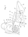
- Figure 1 shows a schematic representation of a plan view of the workpiece table Crankshaft grinding machine with a measuring device according to the invention approximately in the indicated by arrow A in Figure 3.
- Figure 2 shows a schematic View of the device according to the invention along the line B-B of Figure 1. Same parts are provided with the same reference symbols in the figures.
- the machine bed of a crankshaft grinding machine is referred to, on which a Grinding headstock, not shown, can be moved with a grinding wheel 2 in the direction of arrow 3 is.
- a workpiece table or on the machine bed 1 Transverse to the grinding wheel 2 is a workpiece table or on the machine bed 1 Workpiece slide 4 guided in the direction of arrow 6.
- the workpiece carriage 4 carries a workpiece headstock 7 and a tailstock 8 with centering tips, between which a crankshaft 9 is clamped in the usual manner.
- the workpiece spindle is one Motor 11 driven with an angle encoder 12 for detecting the angular position of the Crankshaft 9 is connected.
- the workpiece slide 4 is shown in FIG Direction of arrow 6 positioned so that a crank pin 13 as a workpiece in front of the grinding wheel 2 is in the processing position.
- a measuring device 16 for detecting the Diameter of the crank pin 13 during its processing by the grinding wheel 2 arranged.
- This measuring device 16 has a measuring head 17 with probes 18.
- the measuring head 17th is attached to a measuring head carrier 21 which can be pivoted about a pivot axis 19.
- the swivel drive 22 is on a boom 24 the console 14 hinged.
- a bearing block 26 carries the pivot bearing 27 of the measuring head carrier 21.
- the bearing block 26 is on the bracket in a receptacle 28 by means of a positioning element 29 positioned in a correct position to the rotating crank pin 13 and by means of clamping means, for example clamping screws 31.
- the positioning element 29 has a stop surface 32 for the extreme lower pivoting position of the measuring head carrier 21 on.
- the measuring head carrier 21 is provided with a rigid guide ruler 33 which is in orbit 34 of the workpiece 13 about a circumferential axis 36, in the given example the crankshaft axis, intervenes.
- the guide ruler 33 extends over the length of the Key 18 also tangential to the peripheral surface 37 of the crank pin 13 in its path of movement inside.
- the measuring head 17 is turned by swiveling the measuring head carrier 21 by means of the drive 22 in its extreme lower position shown in FIG. 2 pivoted, in which the measuring head carrier on the stop surface 32 of the positioning element 29 rests. In this position, the measuring head 17 is to the movement path 34 of the Crank pin 13 aligned that the peripheral surface 37 of the crank pin when touched with the tip of the guide ruler 33 sliding tangentially to a guide surface 38 of the guide ruler. As the crank pin 13 moves further its path of movement 34 slides along its circumferential surface 37 along the guide surface 38 and swivels the measuring head clockwise around the swivel axis 19 Drive 22 is switched off so that it pivots the measuring head 17th opposed no resistance.
- the crank pin 13 has the measuring position in the detection area 39 between the Measuring probes 18 reached, in which both probes tap the diameter D of the workpiece and the measuring head 17 generates a diameter signal.
- the measurement is now taking place when the workpiece axis 41 passes through the pivot axis 19 of the measuring head 17 and the plane 42 connecting the axis of rotation 36 of the workpiece, which is shown in FIG is shown in dash-dotted lines.
- the relative movement between the Touch surfaces of the buttons 18 and the circumferential surface of the workpiece in the longitudinal direction of the Push buttons their minimum, so that here a largely trouble-free tapping of the diameter D is optimally guaranteed.
- crank pin 13 The further movement of the crank pin 13 along its movement path 34 in the direction of the arrow 43 pivots the measuring head 17 further clockwise until the guide surface 38 of the Guide rulers 33 in the exit position shown in Figure 4 tangential to the peripheral surface 37 of the crank pin 13 extends. In this position, (in Figure 4 are the same parts again with the same reference numerals as in Figures 1 to 3) the crank pin is released 13 sliding and smooth from the guide surface 38 of the guide ruler 33. Thereby the measurement possibly falsifying vibrations in the measuring head are avoided.
- the Angle encoder 12 (see Fig. 1) of the crankshaft drive 11 in a predetermined angular position the crankshaft sends a signal to a control arrangement 44, which drives the swivel drive 22 in Gear sets, which then the measuring head carrier 21 with the measuring head 17 counterclockwise moved against the stop surface 32 to move the measuring head into that shown in FIG. position suitable for the next diameter measurement.
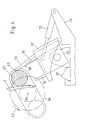
- Figures 5 to 9 show a variant of the diameter detection of an eccentrically rotating Workpiece with a measuring head, the pivoting movement of which is numerically controlled is.
- the workpiece for example again a crank pin 13 of an otherwise not shown Crankshaft, runs as in the case of Figures 1 to 4 along the path of movement 34 in the direction of arrow 43.
- This orbital movement is as in the case of Figure 1 by the Crankshaft drive 11 driven, the angular position detected by the rotary encoder 12 becomes.
- the rotation angle transmitter 12 generates the rotation angle position of the crankshaft Angle signals which it sends to the control arrangement 44, for example the machine control, delivers.
- the measuring head is designed in this variant as well as that in connection with the Figures 1 to 4 shown and is also designated by the reference number 17.
- the structure the measuring head arrangement is not shown again in FIGS. 5 to 9. He can be designed as shown in Figures 1 to 4, the pivot drive 22 and the stop surface 32 is eliminated. Instead, the pivoting movement of the measuring head 17 driven by a motor 46 which is dependent on the control arrangement 44 the angular position of the workpiece 13 is controlled on its path of motion 34.
- the different Positions that the measuring head 17 during the detection of a workpiece diameter occupies are shown in Figures 5 to 8.
- the measuring head 17 is pivoted into an entry position in which the Push button 18 aligned tangentially to the peripheral surface 37 of the incoming crank pin 13 are and engage in the movement path 34 of the crank pin.
- the Crank pin 13 in the detection area 39 between the buttons 18 of the measuring head 17th moves, the contact between the buttons and the peripheral surface of the workpiece when entering the detection area due to the tangential orientation of the buttons largely smooth and smooth.
- the crank pin 13 continues the measuring head 17 is simultaneously moved along its movement path 34 by the drive 46 depending on the angular position of the workpiece 13 about its axis 19 in Pivoted clockwise so that always between the two buttons 18 and the workpiece a stress-free touch takes place.
- Figure 7 shows the measuring position of the measuring head 17, which is defined in that the workpiece axis 41 which the pivot axis 19 of the Measuring head and plane 42 connecting axis of rotation of the workpiece passes.
- the diameter is recorded again in a workpiece position, in which the longitudinal movement of the workpiece along the buttons 18 is very small. This increases the reliability of the diameter measurement.
- the workpiece 13 rotates along its path of movement 34 leave the detection area 39 of the button 18 and completes its circulation while at the same time, what is not shown in Figures 5 to 9, further in contact with the grinding wheel is and is ground.
- the measuring head 17 is now contrary to Pivoted clockwise around its pivot axis 19 into the entry position of FIG. 5, in order for the next diameter measurement in the next revolution of the Workpiece.
- This return movement of the measuring head is due to the control arrangement 44 depending on the angular position of the workpiece on its path of movement controlled to avoid collisions between the workpiece and the feelers during to avoid this backward movement.
- Figure 9 shows an inactive position of the measuring head 17, in which a detection of the Diameter of the workpiece 13 when its axis passes through the connection plane 42 did not take place.
- the diameter D becomes eccentric circulating workpiece not during the entire workpiece circulation, but only recorded in a certain orbit section.
- This orbit section is defined by the overlap of the movement path 34 of the workpiece 13 with the detection area 39 between the buttons 18 of the measuring head 17. It may be sufficient the diameter of the workpiece 13 in this orbit section only one Times to capture and through the control arrangement to a corresponding diameter signal to process. It is of course also possible within the scope of the invention Detect diameters multiple times within the specified orbit section and to form corresponding single or average signals of the diameter. In any case it is sufficient for the measurement-controlled grinding of eccentrically rotating workpieces, to record the diameter only once during the revolution. This is especially true when the grinding wheel is not fed continuously, but only once the grinding wheel is fed during each workpiece revolution.
- a commercially available measuring head with two is used for the diameter measurement measuring probes movable relative to each other can be used.
- the absolute diameter measurement but it is also possible if a movable probe changes the workpiece diameter measures against a rigid reference element, i.e. the second probe is rigid as a reference element is arranged on the measuring head. This variant is not specifically shown in the drawing. It can be realized by using the measuring head design according to FIGS. 2 to 4 button 18 lying on the side of the guide ruler 33 is rigidly arranged or omitted. The guide ruler 33 then simultaneously fulfills the task of a rigid button or Reference element for diameter measurement with the second, movable button.
Landscapes
- Engineering & Computer Science (AREA)
- Mechanical Engineering (AREA)
- Physics & Mathematics (AREA)
- General Physics & Mathematics (AREA)
- Machine Tool Sensing Apparatuses (AREA)
- A Measuring Device Byusing Mechanical Method (AREA)
- Constituent Portions Of Griding Lathes, Driving, Sensing And Control (AREA)
Claims (14)
- Procédé pour mesurer le diamètre (D) d'une pièce à usiner (13), qui circule en position excentrée, suivant un mouvement de révolution, autour d'un axe de révolution (36), par exemple d'un maneton (13) d'un vilebrequin (9) tournant sur une machine-outil, notamment une machine à rectifier, pendant son usinage, selon lequel des palpeurs de mesure (18) d'une tête de mesure de diamètre (17) sont appliqués sur la surface circonférentielle de la pièce à usiner (13) et le diamètre (D) de la pièce à usiner est détecté alors que la tête de mesure (17) est contrainte de suivre le déplacement de la pièce à usiner (13), caractérisé en ce que les palpeurs de mesure (18) de la tête de mesure (17) ne sont appliqués sur la pièce à usiner circulante (13) que dans une partie prédéterminée de la trajectoire de circulation, et en ce que le diamètre (D) de la pièce à usiner est détecté lors du parcours de cette partie prédéterminée de la trajectoire de circulation.
- Procédé selon la revendication 1, caractérisé en ce que le diamètre (D) de la pièce à usiner n'est détecté qu'une fois pendant une révolution de la pièce à usiner, lors du parcours de la partie prédéterminée de la trajectoire de circulation.
- Procédé selon la revendication 1 ou 2, caractérisé en ce que pendant sa circulation, la pièce à usiner (13) est amenée à entrer, au début de la partie prédéterminée de la trajectoire de circulation, dans une zone de détection (39) située entre les palpeurs de mesure (18), en ce que le diamètre (D) de la pièce à usiner (13) est détecté lors du passage dans la partie de la trajectoire de circulation et en ce que la pièce à usiner (13) est amenée à sortir de la zone de détection (39) des palpeurs (18) à la fin de la partie de la trajectoire de circulation.
- Procédé selon l'une des revendications 1 à 3, caractérisé en ce que pendant le parcours de la partie prédéterminée de la trajectoire de circulation par la pièce à usiner (13), la tête de mesure (17) pivote autour d'un axe (19) parallèle à l'axe (36) de la trajectoire de circulation (34) et en ce que le mouvement de pivotement de la tête de mesure (17) est conduit et commandé en fonction du déplacement de la pièce à usiner (13) sur la partie de la trajectoire de circulation.
- Procédé selon la revendication 4, caractérisé en ce que le mouvement de pivotement de la tête de mesure (17) est conduit et guidé par la pièce à usiner (13) elle-même parcourant la partie prédéterminée de la trajectoire de circulation.
- Procédé selon la revendication 4 ou 5, caractérisé en ce que la mesure du diamètre (D) de la pièce à usiner est exécutée approximativement lors du passage de la pièce à usiner (13) par un plan (42) qui relie l'axe de pivotement (19) de la tête de mesure (17) et l'axe (36) de la trajectoire de circulation (34) de la pièce à usiner (13).
- Dispositif pour mesurer le diamètre (D) d'une pièce à usiner (13) qui circule en position excentrée, suivant un mouvement de révolution, autour d'un axe de révolution (36), par exemple d'un maneton (13) d'un vilebrequin (9) tournant sur une machine-outil, notamment une machine à rectifier, pendant son usinage, comprenant une tête de mesure de diamètre (17), qui peut pivoter autour d'un axe fixe (19) parallèle à l'axe de révolution (36), comporte des palpeurs de mesure (18), qui s'appliquent sur la surface circonférentielle (37) de la pièce à usiner (13) pour mesurer le diamètre (D), et est disposée de manière à suivre le déplacement de la pièce à usiner (13) pendant la mesure, caractérisé en ce que la trajectoire de déplacement des palpeurs de mesure (18), lors du mouvement de pivotement de la tête de mesure (17) autour de son axe de pivotement (19), coupe la trajectoire de circulation (34) de la pièce à usiner (13) dans une partie prédéterminée de la trajectoire de circulation, en ce que la tête de mesure (17) peut être amenée par pivotement, en fonction du mouvement de circulation d'une pièce à usiner (13) dans la zone d'intersection, d'une position d'entrée, dans laquelle les palpeurs de mesure (18) sont orientés au moins approximativement tangentiellement à la trajectoire de circulation (34) de la pièce à usiner (13), en sens opposé au sens de circulation, dans une position de sortie, dans laquelle les palpeurs de mesure (18) sont orientés au moins approximativement tangentiellement à la trajectoire de circulation (34) de la pièce à usiner (13), dans le sens de circulation, et en ce que, dans la position d'entrée de la tête de mesure (17), la trajectoire de circulation (34) de la pièce à usiner (13) pénètre dans une zone de détection (39) recevant la pièce à usiner (13) qui doit être mesurée, située entre les palpeurs de mesure (18) de la tête de mesure (17), alors que dans la position de sortie de la tête de mesure, elle ressort de cette zone de détection.
- Dispositif selon la revendication 7, caractérisé en ce qu'à la tête de mesure (17) sont associés des moyens d'entraínement (13, 46) qui font pivoter la tête de mesure depuis une position d'entrée, dans laquelle les palpeurs de mesure (18) sont orientés au moins approximativement tangentiellement au début de la partie prédéterminée de la trajectoire de circulation pour l'introduction de la pièce à usiner (13) dans la zone de détection (39), jusque dans une position de sortie, dans laquelle les palpeurs de mesure (18) sont orientés au moins approximativement tangentiellement à la trajectoire de déplacement (34) de la pièce à usiner à la fin de la partie de la trajectoire de circulation, pour laisser sortir la pièce à usiner (13) de la zone de détection (39), en passant à travers une zone de mesure dans laquelle les palpeurs (18) mesurent le diamètre (D) de la pièce à usiner (13).
- Dispositif selon la revendication 8, caractérisé en ce que le moyen d'entraínement (46) de la tête de mesure (17) est raccordé à un dispositif de commande (44), qui est conçu de manière à commander le mouvement de pivotement de la tête de mesure en fonction du mouvement de circulation d'une pièce à usiner (13) entrant dans la zone de détection (39) des palpeurs de mesure (18), sur la partie prédéterminée de la trajectoire de circulation.
- Dispositif selon la revendication 8, caractérisé en ce que la pièce à usiner circulante (13), qui s'engage dans la zone de détection (39) des palpeurs de mesure (18), est en elle-même prévue comme moyen d'entraínement pour le mouvement de pivotement de la tête de mesure (17).
- Dispositif selon l'une des revendications 7 à 10, caractérisé en ce que l'un des palpeurs (18) de la tête de mesure (17) est conçu sous la forme d'un élément de référence rigide.
- Dispositif selon l'une des revendications 7 à 11, caractérisé en ce que la tête de mesure (17) possède une règle rigide de guidage (33), qui, lorsque la tête de mesure est dans sa position d'entrée, s'engage, au niveau de la face avant de la pièce à usiner (13), dans la trajectoire de circulation (34) de cette dernière, et contre laquelle la pièce à usiner (13) s'applique lorsqu'elle parcourt la partie prédéterminée de la trajectoire de circulation pour faire pivoter la tête de mesure (17) de sa position d'entrée dans sa position de sortie.
- Dispositif selon la revendication 12, caractérisé en ce que la règle de guidage (33) est prévue simultanément comme élément de référence pour la mesure du diamètre (D) de la pièce à usiner.
- Dispositif selon l'une des revendications 10 à 13, caractérisé en ce qu'il est prévu un dispositif d'entraínement de rappel (22), qui ramène par pivotement la tête de mesure (17) de sa position de sortie dans sa position d'entrée.
Applications Claiming Priority (2)
| Application Number | Priority Date | Filing Date | Title |
|---|---|---|---|
| DE19616353A DE19616353A1 (de) | 1996-04-24 | 1996-04-24 | Verfahren und Vorrichtung zum Messen des Durchmessers exzentrisch umlaufender Werkstücke |
| DE19616353 | 1996-04-24 |
Publications (2)
| Publication Number | Publication Date |
|---|---|
| EP0803323A1 EP0803323A1 (fr) | 1997-10-29 |
| EP0803323B1 true EP0803323B1 (fr) | 2000-11-15 |
Family
ID=7792300
Family Applications (1)
| Application Number | Title | Priority Date | Filing Date |
|---|---|---|---|
| EP97106038A Expired - Lifetime EP0803323B1 (fr) | 1996-04-24 | 1997-04-12 | Procédé et dispositif pour mesurer le diamètre d'un objet tournant excentriquement |
Country Status (2)
| Country | Link |
|---|---|
| EP (1) | EP0803323B1 (fr) |
| DE (2) | DE19616353A1 (fr) |
Families Citing this family (9)
| Publication number | Priority date | Publication date | Assignee | Title |
|---|---|---|---|---|
| DE69809667T2 (de) * | 1997-09-23 | 2003-04-24 | Unova U.K. Ltd., Aylesbury | Verbesserungen an oder in Bezug auf Messen |
| DE19840801B4 (de) | 1998-09-08 | 2005-09-15 | Walter Maschinenbau Gmbh | Werkzeugmaschine mit automatischer Prozesssteuerung/Überwachung und Verfahren zum Bearbeiten |
| DE102007060661B4 (de) * | 2007-12-17 | 2015-09-03 | Erwin Junker Maschinenfabrik Gmbh | Messvorrichtung, an einer Werkzeugmaschine, insbesondere Schleifmaschine, angeordnet, zur Bestimmung der Querschnittsabmessung von rotationssymmetrischen Werkstück-Bereichen |
| DE102011115254A1 (de) | 2011-09-27 | 2013-03-28 | Fritz Studer Ag | Werkzeugmaschine und Verfahren zur Vermessung eines Werkstücks |
| DE102012110673B4 (de) * | 2012-11-07 | 2014-05-15 | Fritz Studer Ag | Werkzeugmaschine und Verfahren zur Vermessung eines Werkstücks |
| CN107214575A (zh) * | 2017-07-31 | 2017-09-29 | 江西杰克机床有限公司 | 一种固定式砂轮防护罩上的翻转量仪测量装置 |
| CN107806809A (zh) * | 2017-10-30 | 2018-03-16 | 浙江精雷电器股份有限公司 | 一种偏心距采集检测设备 |
| CN113483643B (zh) * | 2021-07-05 | 2023-03-31 | 桂林福达曲轴有限公司 | 一种曲轴油孔偏心距的检验方法 |
| CN114111680B (zh) * | 2021-12-04 | 2024-05-14 | 陕西渭河工模具有限公司 | 一种螺尖丝锥斜槽芯径的高精度检测装置及检测方法 |
Family Cites Families (4)
| Publication number | Priority date | Publication date | Assignee | Title |
|---|---|---|---|---|
| DE2211590C3 (de) * | 1971-04-20 | 1980-04-17 | Veb Werkzeugmaschinenkombinat 7. Oktober Berlin, Ddr 1120 Berlin | Absolutmeßsteuergerät für Werkzeugmaschinen, insbesondere Schleifmaschinen |
| DE3521710C2 (de) * | 1984-07-03 | 1994-02-10 | Schaudt Maschinenbau Gmbh | Vorrichtung an einer Werkzeugmaschine, insbesondere an einer Schleifmaschine, zum Messen des Durchmessers exzentrisch umlaufender Werkstücke |
| DE4412682C2 (de) * | 1994-04-13 | 1998-09-03 | Doerries Scharmann Ag I K | Vorrichtung zum Vermessen exzentrisch umlaufender Werkstücke |
| DE4419656C2 (de) * | 1994-06-06 | 1996-05-15 | Naxos Union Schleifmittel | Einrichtung zur Durchmesser- und/oder Rundheitsmessung beim exzentrischen Rundschleifen |
-
1996
- 1996-04-24 DE DE19616353A patent/DE19616353A1/de not_active Withdrawn
-
1997
- 1997-04-12 EP EP97106038A patent/EP0803323B1/fr not_active Expired - Lifetime
- 1997-04-12 DE DE59702626T patent/DE59702626D1/de not_active Expired - Fee Related
Also Published As
| Publication number | Publication date |
|---|---|
| EP0803323A1 (fr) | 1997-10-29 |
| DE59702626D1 (de) | 2000-12-21 |
| DE19616353A1 (de) | 1997-10-30 |
Similar Documents
| Publication | Publication Date | Title |
|---|---|---|
| DE102008061444B4 (de) | Drehmaschine mit einer Messvorrichtung und Verfahren zum Vermessen eines Werkstückes auf solch einer Drehmaschine | |
| DE102005008055B4 (de) | Verfahren zum Vermessen einer programmgesteuerten Werkzeugmaschine | |
| EP0252164B1 (fr) | Méthode et dispositif pour déterminer la position radiale d'un profil neuf obtenu par fraisage | |
| DE4004237C2 (fr) | ||
| DE19928500B4 (de) | Verfahren und Vorrichtung zur automatischen Messung von Prozess- und Werkstückkennwerten beim Schleifen von Zahnrädern | |
| DE102007050111B4 (de) | Verfahren und Anlage-Sensorvorrichtung zu einer Anlagemessung bei einer Werkzeugmaschine | |
| EP2668464B1 (fr) | Dispositif de réglage et/ou de mesure | |
| EP0732981A1 (fr) | Procede et dispositif permettant de biseauter l'extremite d'un tube de maniere conforme aux tolerances de position et de dimensions | |
| EP0803323B1 (fr) | Procédé et dispositif pour mesurer le diamètre d'un objet tournant excentriquement | |
| DE102007050482B4 (de) | Verfahren und Vorrichtung zur Finishbearbeitung | |
| DE10030087B4 (de) | Verfahren und Vorrichtung zum Vermessen und Bearbeiten von Werkstücken | |
| DE4412682C2 (de) | Vorrichtung zum Vermessen exzentrisch umlaufender Werkstücke | |
| DE4432317B4 (de) | Meßvorrichtung für Spanwerkzeuge | |
| EP1593950A1 (fr) | Dispositif de mesure de l' eccentricité radiale des engranages | |
| DE102005029735A1 (de) | Dimensionelle Messmaschine | |
| DE2537086C2 (de) | Einrichtung zum Messen des Verschleißes an einem abgefahrenen und nachzuarbeitenden Schienenrad an einer Drehmaschine | |
| DE10123496A1 (de) | Verzahnungsmessmaschine | |
| EP0317760A1 (fr) | Tête de mesure rotative pour la palpation de surfaces cylindriques d'objets sous investigation | |
| DE10319947B4 (de) | Einrichtung zur Messung der Umfangsgestalt rotationssymmetrischer Werkstücke | |
| DE69705873T2 (de) | Schleifverfahren und -vorrichtung für zylindrische Werkstücke | |
| DE3521710A1 (de) | Vorrichtung an einer werkzeugmaschine, insbesondere an einer schleifmaschine, zum messen des durchmessers exzentrisch umlaufender werkstuecke | |
| DE10205212A1 (de) | Meßeinrichtung für Maschinen zum Bearbeiten von Werkstücken, insbesondere von Kurbelwellen, Nockenwellen | |
| DE3500050C2 (de) | Meßkopf für Rundschleifmaschinen | |
| DE4419909B4 (de) | Vorrichtung zur Kontrolle der geometrischen und dynamischen Genauigkeit eines NC-gesteuerten Arbeitskopfes | |
| WO1984004959A1 (fr) | Procede et dispositif pour mesurer le profil d'une dent |
Legal Events
| Date | Code | Title | Description |
|---|---|---|---|
| PUAI | Public reference made under article 153(3) epc to a published international application that has entered the european phase |
Free format text: ORIGINAL CODE: 0009012 |
|
| AK | Designated contracting states |
Kind code of ref document: A1 Designated state(s): CH DE FR GB IT LI |
|
| 17P | Request for examination filed |
Effective date: 19980404 |
|
| 17Q | First examination report despatched |
Effective date: 19980930 |
|
| GRAG | Despatch of communication of intention to grant |
Free format text: ORIGINAL CODE: EPIDOS AGRA |
|
| 17Q | First examination report despatched |
Effective date: 19991018 |
|
| GRAG | Despatch of communication of intention to grant |
Free format text: ORIGINAL CODE: EPIDOS AGRA |
|
| GRAH | Despatch of communication of intention to grant a patent |
Free format text: ORIGINAL CODE: EPIDOS IGRA |
|
| GRAH | Despatch of communication of intention to grant a patent |
Free format text: ORIGINAL CODE: EPIDOS IGRA |
|
| GRAA | (expected) grant |
Free format text: ORIGINAL CODE: 0009210 |
|
| AK | Designated contracting states |
Kind code of ref document: B1 Designated state(s): CH DE FR GB IT LI |
|
| PG25 | Lapsed in a contracting state [announced via postgrant information from national office to epo] |
Ref country code: IT Free format text: LAPSE BECAUSE OF FAILURE TO SUBMIT A TRANSLATION OF THE DESCRIPTION OR TO PAY THE FEE WITHIN THE PRESCRIBED TIME-LIMIT;WARNING: LAPSES OF ITALIAN PATENTS WITH EFFECTIVE DATE BEFORE 2007 MAY HAVE OCCURRED AT ANY TIME BEFORE 2007. THE CORRECT EFFECTIVE DATE MAY BE DIFFERENT FROM THE ONE RECORDED. Effective date: 20001115 Ref country code: FR Free format text: LAPSE BECAUSE OF FAILURE TO SUBMIT A TRANSLATION OF THE DESCRIPTION OR TO PAY THE FEE WITHIN THE PRESCRIBED TIME-LIMIT Effective date: 20001115 |
|
| REG | Reference to a national code |
Ref country code: CH Ref legal event code: EP |
|
| GBT | Gb: translation of ep patent filed (gb section 77(6)(a)/1977) |
Effective date: 20001115 |
|
| REF | Corresponds to: |
Ref document number: 59702626 Country of ref document: DE Date of ref document: 20001221 |
|
| PG25 | Lapsed in a contracting state [announced via postgrant information from national office to epo] |
Ref country code: GB Free format text: LAPSE BECAUSE OF NON-PAYMENT OF DUE FEES Effective date: 20010412 |
|
| EN | Fr: translation not filed | ||
| PG25 | Lapsed in a contracting state [announced via postgrant information from national office to epo] |
Ref country code: LI Free format text: LAPSE BECAUSE OF NON-PAYMENT OF DUE FEES Effective date: 20010511 Ref country code: CH Free format text: LAPSE BECAUSE OF NON-PAYMENT OF DUE FEES Effective date: 20010511 |
|
| PLBE | No opposition filed within time limit |
Free format text: ORIGINAL CODE: 0009261 |
|
| STAA | Information on the status of an ep patent application or granted ep patent |
Free format text: STATUS: NO OPPOSITION FILED WITHIN TIME LIMIT |
|
| 26N | No opposition filed | ||
| GBPC | Gb: european patent ceased through non-payment of renewal fee |
Effective date: 20010412 |
|
| REG | Reference to a national code |
Ref country code: CH Ref legal event code: PL |
|
| PG25 | Lapsed in a contracting state [announced via postgrant information from national office to epo] |
Ref country code: DE Free format text: LAPSE BECAUSE OF NON-PAYMENT OF DUE FEES Effective date: 20020201 |