EP0803304A2 - Holding vessel with graphite or metallic prechamber - Google Patents
Holding vessel with graphite or metallic prechamber Download PDFInfo
- Publication number
- EP0803304A2 EP0803304A2 EP97100045A EP97100045A EP0803304A2 EP 0803304 A2 EP0803304 A2 EP 0803304A2 EP 97100045 A EP97100045 A EP 97100045A EP 97100045 A EP97100045 A EP 97100045A EP 0803304 A2 EP0803304 A2 EP 0803304A2
- Authority
- EP
- European Patent Office
- Prior art keywords
- crucible
- holding
- metal
- antechamber
- graphite
- Prior art date
- Legal status (The legal status is an assumption and is not a legal conclusion. Google has not performed a legal analysis and makes no representation as to the accuracy of the status listed.)
- Withdrawn
Links
Images
Classifications
-
- F—MECHANICAL ENGINEERING; LIGHTING; HEATING; WEAPONS; BLASTING
- F27—FURNACES; KILNS; OVENS; RETORTS
- F27B—FURNACES, KILNS, OVENS, OR RETORTS IN GENERAL; OPEN SINTERING OR LIKE APPARATUS
- F27B14/00—Crucible or pot furnaces
- F27B14/08—Details peculiar to crucible or pot furnaces
- F27B14/10—Crucibles
-
- B—PERFORMING OPERATIONS; TRANSPORTING
- B22—CASTING; POWDER METALLURGY
- B22D—CASTING OF METALS; CASTING OF OTHER SUBSTANCES BY THE SAME PROCESSES OR DEVICES
- B22D41/00—Casting melt-holding vessels, e.g. ladles, tundishes, cups or the like
- B22D41/04—Casting melt-holding vessels, e.g. ladles, tundishes, cups or the like tiltable
- B22D41/05—Tea-pot spout ladles
Definitions
- the invention relates to a holding crucible with a prechamber made of graphite or metal for molten metals with holding temperature fittings between 700 o C and 1000 o C.
- metals or metal alloys are premelted at the temperatures mentioned - generally aluminum alloys - in so-called premelting furnaces and heated to the desired temperature.
- Such premelting furnaces are mainly heated with oil or gas. If there is a greater need for liquid aluminum alloys, induction furnaces are used. Aluminum alloys require special maintenance.
- the hydrogen bubbles can make themselves unpleasantly noticeable as the smallest voids.
- the further sensitivity is the strong affinity of aluminum or aluminum alloys for oxygen.
- Aluminum and its alloys oxidize very easily and on every occasion, especially where oxygen or oxygen compounds are nearby.
- Aluminum oxides are formed. This fault formation is particularly pronounced in liquid aluminum alloys. The oxides then appear as oxide skins and float in the melt in order to then deposit on the grain boundaries when the castings solidify later.
- melts can be cleaned relatively easily, both from the hydrogen and from the oxides.
- the most intensive, fastest and most complete cleaning of the melt is carried out by blowing chlorine gas into the melt.
- this method has the disadvantage of being extremely polluting, so that it is only used in the toughest cases. Otherwise, cleaning salts are used to clean the melt, but they also release small amounts of chlorine gas for more intensive cleaning.
- the melt in the premelting furnace can be cleaned relatively well, even with chlorine gas, since nobody works on a premelting furnace as a caster. Suitable protective measures can easily be taken.
- the object of the invention is now to significantly reduce oxide formation when transferring the premelt into the crucible of the holding furnaces.
- the crucibles are almost the same in shape for both holding furnaces and premelting furnaces, but differ in capacity.
- the crucibles have a circular, elongated shape and are at least domed in the base area.
- the holding crucible (1) Fig.1 inform of a graphite crucible has a uniform course in the upper region with respect to the end of the wall thickness.
- a holding crucible made of metal (1.1) Fig. 3,4 is usually made of cast iron or cast iron - in exceptional cases also as cast steel.
- FIGS. 3 and 4 Another solution is shown graphically in FIGS. 3 and 4.
- the crucible wall (2.1) Fig. 3, 4 is left free at any circumferential point on the long side up to a certain length, in the width corresponding to the interior space dimension (5), Fig. 3 of the pre-chamber (4.1), A connecting separator (7) Fig. 5,6,8 is later inserted into this clearance (6) Fig. 7.
- the crucible wall (2.1) Fig.3 has reinforcements (9) Fig.3,4 in the area of the molded pre-chamber (3.1), in which longitudinal grooves (10) Fig.3.4 are provided, in which the longitudinal ribs (11) Fig.5.8 of the connecting separating piece (7) engage in a holding manner.
- the length (L) Fig. 8 of the connecting: separating piece (7) Fig. 8 is dimensioned such that after the connecting separating piece (7) has been fully inserted into the recess (6) Fig. 7, a connecting opening (8.1) Fig. 4, 6 between the crucible interior (12) Fig. 3.5 and the pre-chamber interior (13) Fig. 3.5 remains.
- the upper edge of the crucible is provided with a circumferential crucible edge (14) Fig. 3, 4, 5, 7 to reinforce and prevent the risk of breakage.
- the crucible rim (14) has one in the area of the antechamber inclined abbreviation (15) Fig. 3, 4, 5, 6, 7 to shield liquid metal to be introduced.
- graphite crucibles In graphite crucibles, graphite conducts heat well, but metal transfers heat even better. In the case of graphite crucibles, the thermal conductivity drops relatively quickly, since graphite crucibles become refractory over time. A graphite crucible must therefore be replaced after about 6 to 8 weeks for cost reasons.
- a metal crucible loses the thermal conductivity insignificantly, and the durability and usability can be 1 to 2 years. These circumstances clearly speak for the use of metal crucibles.
- aluminum and aluminum alloys have the property of dissolving iron. Iron is then found in the mixed crystals and becomes very brittle from a certain percentage of aluminum alloys.
Abstract
Description
Die Erfindung betrifft einen Warmhaltetiegel mit Vorkammer aus Graphit oder Metall für Metallschmelzen mit Warmhaltetempearaturen zwischen 700o C und 1000o C.
Meistens werden Metalle bzw. Metall-Legierungen bei den erwähnten Temperaturen - in der Regel Aluminium-Legierungen - in sogenannten Vorschmelzöfen vorgeschmolzen und auf die gewünschte Temperatur erhitzt.
Solche Vorschmelzöfen werden vorwiegend mit Öl oder Gas beheizt.
Bei größerem Bedarf an flüssigen Alu-Legierungen setzt man Induktionsöfen ein.
Alu-Legierungen bedürfen einer besonderen Wartung.
Einmal vergast die Schmelze sehr leicht.
Vergasen nennt man in Fachkreisen die Aufnahme von Wasserstoff.
Wasserstoff wird durch Abspaltung bei entsprechenden Wasserstoffverbindungen, beispielsweise Wasser, frei und schwebt in der Schmelze als kleine kugelförmige Bläschen.The invention relates to a holding crucible with a prechamber made of graphite or metal for molten metals with holding temperature fittings between 700 o C and 1000 o C.
Mostly, metals or metal alloys are premelted at the temperatures mentioned - generally aluminum alloys - in so-called premelting furnaces and heated to the desired temperature.
Such premelting furnaces are mainly heated with oil or gas.
If there is a greater need for liquid aluminum alloys, induction furnaces are used.
Aluminum alloys require special maintenance.
Once the melt gasifies very easily.
In professional circles, gasification is called the absorption of hydrogen.
Hydrogen is released by splitting off corresponding hydrogen compounds, for example water, and hovers in the melt as small spherical bubbles.
Bei später langsamer Erkaltung der Gußteile können sich die Wasserstoffbläschen als kleinste Hohlräume unangenehm bemerkbar machen.
Die weitere Empfindlichkeit ist starke Affinität Aluminiums bzw. der Alu-Legierungen zum Sauerstoff.If the castings slowly cool down later, the hydrogen bubbles can make themselves unpleasantly noticeable as the smallest voids.
The further sensitivity is the strong affinity of aluminum or aluminum alloys for oxygen.
Durch diese Eigenschaft oxidieren Aluminium und seine Legierungen sehr leicht und bei jeder Gelegenheit, insbesondere dort, wo Sauerstoff oder Sauerstoffverbindungen in der Nähe sind.
Es bilden sich Aluminiumoxide.
Besonders stark ausgeprägt ist diese Fehlerbildung bei flüssigen Alu-Legierungen.
Die Oxide treten dann als Oxidhäute auf und schweben in der Schmelze, um sich dann bei späterer Erstarrung der Gußteile an den Korngrenzen abzulagern.Due to this property, aluminum and its alloys oxidize very easily and on every occasion, especially where oxygen or oxygen compounds are nearby.
Aluminum oxides are formed.
This fault formation is particularly pronounced in liquid aluminum alloys.
The oxides then appear as oxide skins and float in the melt in order to then deposit on the grain boundaries when the castings solidify later.
Zum Glück lassen sich die Schmelzen relativ leicht, sowohl vom Wasserstoff als auch von den Oxiden,reinigen.
Die intensivste, schnellste und vollkommenste Reinigung der Schmelze erfolgt durch Einblasen von Chlorgas in die Schmelze.
Diese Methode hat aber leider den Nachteil, sehr stark umweltbelastend zu sein, so daß man hierauf nur in den härtesten Fällen zurückgreift.
Sonst werden zur Reinigung der Schmelze Reinigungssalze eingesetzt, die zur stärkeren Reinigung jedoch auch in geringen Mengen Chlorgas abspalten.Fortunately, the melts can be cleaned relatively easily, both from the hydrogen and from the oxides.
The most intensive, fastest and most complete cleaning of the melt is carried out by blowing chlorine gas into the melt.
Unfortunately, this method has the disadvantage of being extremely polluting, so that it is only used in the toughest cases.
Otherwise, cleaning salts are used to clean the melt, but they also release small amounts of chlorine gas for more intensive cleaning.
Die Schmelze im Vorschmelzofen kann relativ gut gereinigt werden, selbst mit Chlorgas, da an einem Vorschmelzofen niemand als Giesser arbeitet.
Geeignete Schutzmassnahmen können leicht getroffen werden.The melt in the premelting furnace can be cleaned relatively well, even with chlorine gas, since nobody works on a premelting furnace as a caster.
Suitable protective measures can easily be taken.
Selbst die reinste Vorschmelze wird spätestens dann wieder zum Problemfall, wenn die Teilumfüllung in die Warmhalteöfen erfolgt bzw. erfolgen muß.Even the purest premelt becomes a problem again at the latest when the partial transfer into the holding furnaces takes place or must be done.
Für die Teileinbringung der Vorschmelze in die Warmhalteöfen gibt es nur zwei praktikable Lösungen.
Entweder erfolgt eine Direkteinkippung der Vorschmelze vom Vorschmelzofen in den Tiegel des Warmhalteofens oder es erfolgt eine manuelle Umschöpfung der Vorschmelze in den Tiegel des Warmhalteofens.
In beiden Fällen wird sowohl die Vorschmelze als auch das im Tiegel des Warmhalteofens befindliche Flüssigmetall durchgewirbelt, wobei zwangsläufig verstärkt die nicht erwünschten Oxidhäute allein durch die Lufteinwirkung entstehen.
Diese entstandenen Fehler müssen dann durch sofortige Reinigung des flüssigen Metalls im Tiegel des Warmhalteofens sorgfältigst behoben werden.
Neben dem Zeitaufwand selbst bedeutet dies auch eine Unterbrechung des Arbeitstaktes der am Warmhalteofen beschäftigten Giesser.There are only two practical solutions for the partial introduction of the pre-melt into the holding furnace.
Either the premelt is tipped directly from the premelting furnace into the crucible of the holding furnace or the premelt is manually scooped into the crucible of the holding furnace.
In both cases, both the premelt and the liquid metal located in the crucible of the holding furnace are whirled through, whereby the undesirable oxide skins inevitably arise solely from the air.
These errors must then be carefully eliminated by immediately cleaning the liquid metal in the crucible of the holding oven.
In addition to the time itself, this also means an interruption in the work cycle of the foundryers employed at the holding furnace.
Aufgabe der Erfindung ist es nun, beim Umfüllen der Vorschmelze in die Tiegel der Warmhalteöfen eine Oxidbildung erheblich zu mindern.The object of the invention is now to significantly reduce oxide formation when transferring the premelt into the crucible of the holding furnaces.
Diese Aufgabe ist durch den kennzeichnenden Teil des Anspruchs 1 gelöst.
Unteransprüche kennzeichnen besondere Merkmale der Erfindung.This object is solved by the characterizing part of
Sub-claims characterize special features of the invention.
Die Erfindung ist anhand von Zeichnungen dargestellt, worauf die Erfindung jedoch nicht beschränkt ist.
Es ist möglich und denkbar, dass sich aus dem Hauptanspruch, den Unteransprüchen, der Beschreibung und den Erklärungen zu den Zeichnungen Umstände ergeben, die für sich selbst oder in verschiedenen Kombinationen erfindungsbedeutsam sein können.The invention is illustrated with the aid of drawings, to which the invention is, however, not restricted.
It is possible and conceivable that circumstances arise from the main claim, the subclaims, the description and the explanations for the drawings, which may be significant to the invention by itself or in various combinations.
Der Erfindungsgegenstand ist in den Zeichnungen dargestellt.The subject of the invention is shown in the drawings.
Es zeigen:
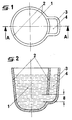
- Fig. 1
- eine Aufsichtszeichnung eines Warmhaltetiegels aus Graphit,
- Fig. 2
- eine Querschnittszeichnung gemäss Schnitt A-A (Fig.1),
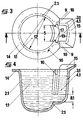
- Fig. 3
- eine Aufsichtszeichnung eines Warmhaltetiegels aus Metall,
- Fig. 4
- eine Querschnittszeichnung gemäss Schnitt B-B (Fig.3),
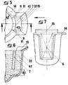
- Fig. 5
- eine Teilaufsichtszeichnung eines Warmhaltetiegels aus Metall,
- Fig. 6
- eine Teilquerschnittszeichnung gemäss Schnitt C-C (Fig.5),
- Fig. 7
- eine Teilansichtszeichnung in Richtung D,
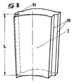
- Fig. 8
- eine vergrösserte perspektivische Zeichnung.
- Fig. 1
- a plan drawing of a holding crucible made of graphite,
- Fig. 2
- a cross-sectional drawing according to section AA (Fig.1),
- Fig. 3
- a top view drawing of a metal holding crucible,
- Fig. 4
- a cross-sectional drawing according to section BB (Fig.3),
- Fig. 5
- a partial supervision drawing of a metal holding crucible,
- Fig. 6
- a partial cross-sectional drawing according to section CC (Fig.5),
- Fig. 7
- a partial view drawing in direction D,
- Fig. 8
- an enlarged perspective drawing.
Normalerweise sind die, Tiegel sowohl für Warmhalteöfen als auch für Vorschmelzöfen in der Form fast gleich, im Fassungsvermögen jedoch unterschiedlich.
Die Tiegel weisen eine kreisrunde, länglich gestreckte Form auf und sind im Bodenbereich zumindest bombiert.Usually, the crucibles are almost the same in shape for both holding furnaces and premelting furnaces, but differ in capacity.
The crucibles have a circular, elongated shape and are at least domed in the base area.
Der Warmhaltetiegel (1) Fig.1 inform eines Graphittiegels weist im oberen Bereich bezüglich der Wandstärkenendung einen gleichmässigen Verlauf auf.
Erfindungsgemäss kann bei einem Graphittiegel die Verbindungsöffnung (8) Fig.2 zwischen dem eigentlichen WarmhalteTiegel (1) Fig.1,2 der angeformten Vorkammer (4) Fig.1,2 nach der Gesamtformgebung nachträglich noch manuell nachgeformt werden.The holding crucible (1) Fig.1 inform of a graphite crucible has a uniform course in the upper region with respect to the end of the wall thickness.
According to the invention, in the case of a graphite crucible, the connection opening (8), FIG. 2, between the actual heating crucible (1) Fig. 1, 2 of the pre-chamber (4) Fig. 1, 2, after the overall shaping, be subsequently reshaped manually.
Ein Warmhaltetiegel aus Metall (1.1) Fig.3,4 ist in der Regel aus Grauguss oder Ferritguß - in Ausnahmefällen auch als Stahlguss - gefertigt.A holding crucible made of metal (1.1) Fig. 3,4 is usually made of cast iron or cast iron - in exceptional cases also as cast steel.
Bei einem Gussteil ist zwar die Anformung der geschlossenen Vorkammer (3.1 Fig. 3,4 ohne Schwierigkeiten möglich,jedoch kann die Verbindungsöffnung (8.1) Fig.2 formtechnisch nicht ausgeführt werden, weshalb eine andere Lösung berücksichtigt werden muss.In the case of a cast part, it is possible to form the closed prechamber (3.1, Fig. 3.4) without difficulty, but the connection opening (8.1), Fig. 2 cannot be designed in terms of shape, which is why another solution must be considered.
In Fig.3 und 4 ist eine andere Lösung zeichnerisch dargestellt.
Die Tiegelwand (2.1) Fig.3,4 ist an einer beliebigen Umfangsstelle längsseitig bis auf eine bestimmte Länge, in der Breite entsprechend dem Innenraummass (5) Fig.3 der angeformten Vorkammer (4.1) Fig.3 freigespart.
In diese Freisparung (6) Fig.7 wird später ein verbindendes Trennstück (7) Fig. 5,6,8 eingeschoben.
Damit dieses verbindende Trennstück (7) in der Tiegelwand (2.1) Fig.3 lockerungssicher sitzt, weist die Tiegelwand (2.1) Fig.3 im Bereich der angeformten Vorkammer (3.1) Verstärkungen (9) Fig.3,4 auf, in denen Längsnuten (10) Fig.3,4 vorgesehen sind, in die die Längsrippen (11) Fig.5,8 des verbindenen Trennstücks (7) halternd eingreifen.
Die Länge (L) Fig.8 des verbindenden: Trennstücks (7) Fig.8 ist so bemessen, dass nach vollkommener Einführung des verbindenden Trennungsstücks (7) in die Freisparung (6) Fig.7 eine Verbindungsöffnung (8.1) Fig.4,6 zwischen Tiegelinnenraum (12) Fig.3,5 und Vorkammer-Innenraum (13) Fig.3,5 verbleibt.
Der obere Tiegelrand ist zur Verstärkung und Verhinderung einer möglichen Bruchgefahr mit einem umlaufenden Tiegelrand (14) Fig.3,4,5,7 versehen.Another solution is shown graphically in FIGS. 3 and 4.
The crucible wall (2.1) Fig. 3, 4 is left free at any circumferential point on the long side up to a certain length, in the width corresponding to the interior space dimension (5), Fig. 3 of the pre-chamber (4.1),
A connecting separator (7) Fig. 5,6,8 is later inserted into this clearance (6) Fig. 7.
So that this connecting separator (7) sits loosely in the crucible wall (2.1) Fig.3, the crucible wall (2.1) Fig.3 has reinforcements (9) Fig.3,4 in the area of the molded pre-chamber (3.1), in which longitudinal grooves (10) Fig.3.4 are provided, in which the longitudinal ribs (11) Fig.5.8 of the connecting separating piece (7) engage in a holding manner.
The length (L) Fig. 8 of the connecting: separating piece (7) Fig. 8 is dimensioned such that after the connecting separating piece (7) has been fully inserted into the recess (6) Fig. 7, a connecting opening (8.1) Fig. 4, 6 between the crucible interior (12) Fig. 3.5 and the pre-chamber interior (13) Fig. 3.5 remains.
The upper edge of the crucible is provided with a circumferential crucible edge (14) Fig. 3, 4, 5, 7 to reinforce and prevent the risk of breakage.
Im Bereich der Vorkammer weist der Tiegelrand (14) eine schräge Aufschürzung (15) Fig.3,4,5,6,7 auf, um einzuführendes Flüssigmetall abzuschirmen.The crucible rim (14) has one in the area of the antechamber inclined abbreviation (15) Fig. 3, 4, 5, 6, 7 to shield liquid metal to be introduced.
Bei Graphittiegeln leitet Graphit die Wärme gut, Metall überträgt die Wärme jedoch noch besser.
Bei Graphittiegeln fällt die Wärmeleitfähigkeit relativ schnell ab, da Graphittiegel im Laufe der Zeit schamottieren. Ein Graphittiegel muß aus Kostengründen deshalb nach etwa 6 bis 8 Wochen ausgewechselt werden.In graphite crucibles, graphite conducts heat well, but metal transfers heat even better.
In the case of graphite crucibles, the thermal conductivity drops relatively quickly, since graphite crucibles become refractory over time. A graphite crucible must therefore be replaced after about 6 to 8 weeks for cost reasons.
Ein Metalltiegel verliert die Wärmeleitfähigkeit unwesentlich, und die Haltbarkeit und Brauchbarkeit kann 1 bis 2 Jahre betragen.
Diese Umstände sprechen eindeutig für den Einsatz von Metalltiegeln.A metal crucible loses the thermal conductivity insignificantly, and the durability and usability can be 1 to 2 years.
These circumstances clearly speak for the use of metal crucibles.
Nun haben aber Aluminium und auch Alu-Legierungen die Eigenschaft, Eisen zu lösen.
Eisen findet sich dann in den Mischkristallen wieder und versprödet ab einem gewissen Prozentsatz Alu-Legierungen sehr stark..Now aluminum and aluminum alloys have the property of dissolving iron.
Iron is then found in the mixed crystals and becomes very brittle from a certain percentage of aluminum alloys.
Bei Grauguss ist die Eisenaufnahme durch Alu-Legierungen stark reduziert.
Auch diese relativ geringe Eisenaufnahme wird so gut wie ausgeschlossen, wenn der Graugusstiegel mit einer dauerhaften Schlichte versehen wird.
Diese Schlichtenschicht muß wöchentlich einmal kontrolliert, u.U. ausgebessert bzw. vollkommen erneuert werden.In gray cast iron, the iron absorption by aluminum alloys is greatly reduced.
This relatively low iron absorption is also almost impossible if the gray cast crucible is provided with a permanent size.
This finishing layer must be checked once a week, possibly repaired or completely renewed.
Das Einbringen von Schmelze aus dem Vorschmelzofen in den Tiegel des Warmhalteofens erfolgt grundsätzlich über die Vorkammer.
Eine Durchwirbelung des flüssigen Metalls im Tiegel des Warmhalteofens wird weitestgehend verhindert, denn die Durchgangsöffnung (8),(8.1) Fig.2,4,6 wirkt nach dem Prinzip der kommunizierenden Röhren.
Der Metallspiegel im Tiegelraum des Warmhalteofens steigt ohne Wirbelung langsam bis zur gewünschten Höhe an.The introduction of melt from the premelting furnace into the crucible of the holding furnace basically takes place via the prechamber.
Whirling of the liquid metal in the crucible of the holding furnace is largely prevented, because the through opening (8), (8.1) Fig. 2,4,6 works according to the principle of the communicating tubes.
The metal mirror in the crucible of the holding oven slowly rises to the desired height without swirling.
Eine Oxidhautbildung wird dadurch sehr stark reduziert.
Eine Reinigung des flüssigen Metall in bestimmten Zeitabständen wird dadurch selbstverständlich nicht überflüssig.This significantly reduces the formation of oxide skin.
Of course, cleaning the liquid metal at certain intervals is not superfluous.
- 11
- Warmhaltetiegel aus GraphitWarming crucible made of graphite
- 1.11.1
- Warmhaltetiegel aus MetallHolding crucible made of metal
- 22nd
- Tiegelwand bei Warmhaltetiegeln aus GraphitCrucible wall for holding crucibles made of graphite
- 2.12.1
- Tiegelwand bei Warmhaltetiegeln aus MetallCrucible wall for metal holding crucibles
- 33rd
- geschlossene Vorkammer bei einem Graphittiegelclosed antechamber in a graphite crucible
- 3.13.1
- geschlossene Vorkammer bei einem Metall-Tiegelclosed antechamber in a metal crucible
- 44th
- angeformte Vorkammer bei einem Graphittiegelmolded pre-chamber in a graphite crucible
- 4.14.1
- angeformte Vorkammer bei einem Metall-Tiegelmolded pre-chamber in a metal crucible
- 55
- Innenraummass der angeformten VorkammerInterior dimensions of the molded antechamber
- 66
- Freisparung in der TiegelwandFreeing in the crucible wall
- 77
- verbindendes Trennstückconnecting separator
- 88th
- Verbindungsöffnung bei einem GraphittiegelConnection opening in a graphite crucible
- 8.18.1
- Verbindungsöffnung bei einem Metall-TiegelConnection opening in a metal crucible
- 99
- Verstärkung der TiegelwandReinforcement of the crucible wall
- 1010th
- LängsnutenLongitudinal grooves
- 1111
- LängsrippenLongitudinal ribs
- LL
- Länge des verbindenden TrennstücksLength of the connecting separator
- 1212th
- TiegelinnenraumCrucible interior
- 1313
- VorkammerinnenraumAntechamber interior
- 1414
- umlaufender Tiegelrandall-round crucible rim
- 1515
- schräge Aufschürzungoblique abbreviation
- 1616
- WarmhaltetiegelaussenwandHolding wall outside
- 1717th
- WarmhaltetiegelwandseitenWarming pan wall sides
Claims (4)
dadurch gekennzeichnet,
characterized,
dadurch gekennzeichnet,
characterized,
dadurch gekennzeichnet,
characterized,
dadurch gekennzeichnet,
characterized,
Applications Claiming Priority (2)
| Application Number | Priority Date | Filing Date | Title |
|---|---|---|---|
| DE9600045U | 1996-01-03 | ||
| DE29600045U DE29600045U1 (en) | 1996-01-03 | 1996-01-03 | Holding crucibles with antechamber made of graphite or metal |
Publications (2)
| Publication Number | Publication Date |
|---|---|
| EP0803304A2 true EP0803304A2 (en) | 1997-10-29 |
| EP0803304A3 EP0803304A3 (en) | 1999-06-16 |
Family
ID=8017642
Family Applications (1)
| Application Number | Title | Priority Date | Filing Date |
|---|---|---|---|
| EP97100045A Withdrawn EP0803304A3 (en) | 1996-01-03 | 1997-01-03 | Holding vessel with graphite or metallic prechamber |
Country Status (2)
| Country | Link |
|---|---|
| EP (1) | EP0803304A3 (en) |
| DE (1) | DE29600045U1 (en) |
Cited By (2)
| Publication number | Priority date | Publication date | Assignee | Title |
|---|---|---|---|---|
| WO2005095027A1 (en) * | 2004-04-01 | 2005-10-13 | Outokumpu Technology Oyj | Casting trough and method for casting copper anodes |
| CN100381228C (en) * | 2005-03-17 | 2008-04-16 | 日矿金属株式会社 | Computation hollowware for anode casting |
Families Citing this family (1)
| Publication number | Priority date | Publication date | Assignee | Title |
|---|---|---|---|---|
| DE19831296C2 (en) * | 1998-07-13 | 2002-05-16 | Vesuvius Becker & Piscantor Gr | Holding vessel |
Citations (7)
| Publication number | Priority date | Publication date | Assignee | Title |
|---|---|---|---|---|
| DE30339C (en) * | L. DILL in Frankfurt a. M | Pan for slag-free Gufs | ||
| DE428653C (en) * | 1925-02-08 | 1926-05-08 | Hugo Wachenfeld | Auxiliary device for ladles |
| GB578977A (en) * | 1944-06-23 | 1946-07-18 | Stone J & Co Ltd | Improvements in the treatment of magnesium base alloys and the production of pressure die-castings therefrom |
| GB618563A (en) * | 1946-11-04 | 1949-02-23 | Stone Fry Magnesium Ltd | Improvements relating to the production of pressure die castings from magnesium basealloys |
| US2621916A (en) * | 1949-12-19 | 1952-12-16 | William L Wilbert | Crucible or melting pot |
| DE1907107A1 (en) * | 1969-02-13 | 1970-09-03 | Kabel Metallwerke Ghh | Process for the production of copper-clad aluminum wires |
| DE2512128A1 (en) * | 1974-12-23 | 1976-07-01 | Union Carbide Corp | EXTERNAL HEATED CAST IRON VESSEL FOR REACTIVE METAL MELT AND A PROCESS FOR THE MANUFACTURE OF SUCH A VESSEL |
Family Cites Families (1)
| Publication number | Priority date | Publication date | Assignee | Title |
|---|---|---|---|---|
| DE1907107U (en) * | 1964-08-14 | 1964-12-23 | Bbc Brown Boveri & Cie | TILTABLE INDUCTION FURNACE. |
-
1996
- 1996-01-03 DE DE29600045U patent/DE29600045U1/en not_active Expired - Lifetime
-
1997
- 1997-01-03 EP EP97100045A patent/EP0803304A3/en not_active Withdrawn
Patent Citations (7)
| Publication number | Priority date | Publication date | Assignee | Title |
|---|---|---|---|---|
| DE30339C (en) * | L. DILL in Frankfurt a. M | Pan for slag-free Gufs | ||
| DE428653C (en) * | 1925-02-08 | 1926-05-08 | Hugo Wachenfeld | Auxiliary device for ladles |
| GB578977A (en) * | 1944-06-23 | 1946-07-18 | Stone J & Co Ltd | Improvements in the treatment of magnesium base alloys and the production of pressure die-castings therefrom |
| GB618563A (en) * | 1946-11-04 | 1949-02-23 | Stone Fry Magnesium Ltd | Improvements relating to the production of pressure die castings from magnesium basealloys |
| US2621916A (en) * | 1949-12-19 | 1952-12-16 | William L Wilbert | Crucible or melting pot |
| DE1907107A1 (en) * | 1969-02-13 | 1970-09-03 | Kabel Metallwerke Ghh | Process for the production of copper-clad aluminum wires |
| DE2512128A1 (en) * | 1974-12-23 | 1976-07-01 | Union Carbide Corp | EXTERNAL HEATED CAST IRON VESSEL FOR REACTIVE METAL MELT AND A PROCESS FOR THE MANUFACTURE OF SUCH A VESSEL |
Cited By (4)
| Publication number | Priority date | Publication date | Assignee | Title |
|---|---|---|---|---|
| WO2005095027A1 (en) * | 2004-04-01 | 2005-10-13 | Outokumpu Technology Oyj | Casting trough and method for casting copper anodes |
| EA008872B1 (en) * | 2004-04-01 | 2007-08-31 | Отокумпу Текнолоджи Оюй | Casting trough and method for casting copper anodes |
| CN100553824C (en) * | 2004-04-01 | 2009-10-28 | 奥图泰有限公司 | The method that pouring basin, outlet brick and casting copper anode are used |
| CN100381228C (en) * | 2005-03-17 | 2008-04-16 | 日矿金属株式会社 | Computation hollowware for anode casting |
Also Published As
| Publication number | Publication date |
|---|---|
| DE29600045U1 (en) | 1996-02-29 |
| EP0803304A3 (en) | 1999-06-16 |
Similar Documents
| Publication | Publication Date | Title |
|---|---|---|
| DE3339586C2 (en) | ||
| EP1109640B1 (en) | Metallurgic container | |
| DE69822107T2 (en) | Cooling plate for metallurgical shaft kilns | |
| EP0803304A2 (en) | Holding vessel with graphite or metallic prechamber | |
| EP0181853B1 (en) | Gas flushing plug for metallurgical furnaces and vessels | |
| EP0468950A2 (en) | Plant for producing molten metals | |
| AT509787B1 (en) | WATER COOLED LID FOR A TEMPERED TREATMENT VESSEL FOR METAL MELTS | |
| DE2656929A1 (en) | NICKEL-CHROME ALLOY | |
| WO2004079019A2 (en) | Gas bubbling element and corresponding gas bubbling system | |
| DE1939653C3 (en) | Water-cooled continuous casting mold | |
| DE1083509B (en) | Electric multi-chamber melting furnace for melting down metals with a melting chamber and a holding and removal chamber | |
| DE3805334A1 (en) | Refractory wearing part for the nozzle on metallurgical vessels and a protective sleeve for initial casting with a wearing part of this kind | |
| EP1088112B1 (en) | Water-cooled vessel for vacuum processing of liquid steel | |
| DE3248104C2 (en) | Crucibles for melting and pouring dental alloys | |
| DE2717641C3 (en) | Cooling element for a metallurgical furnace, in particular for a blast furnace | |
| DE10249333B4 (en) | Metallurgical melting vessel | |
| DE2218865A1 (en) | RIDER FOR HEAT CARRIERS IN INDUSTRIAL FURNACES | |
| DE10062308B4 (en) | Container for molten metal, in particular transport vessel, for example, steel ladle | |
| DE972075C (en) | Swiveling shaft furnace, especially for melting down light metal scrap | |
| DE2121746A1 (en) | Cooled channel cleaning tool - for low frequency induction - melting furnaces | |
| DE2719166C3 (en) | Cooling element for a metallurgical furnace | |
| DE4130590C2 (en) | DEGASSING TUBE FOR THE VACUUM TREATMENT OF LIQUID STEEL | |
| DE3827074A1 (en) | METHOD AND DEVICE FOR AVOIDING THE EVAPORATION LOSSES OF ALLOY ELEMENTS IN ELECTRON BEAM MELTS | |
| DE1758194C2 (en) | Agitators for metallurgical purposes | |
| DE1802197C (en) | Induction channel furnace for treating molten metal |
Legal Events
| Date | Code | Title | Description |
|---|---|---|---|
| PUAI | Public reference made under article 153(3) epc to a published international application that has entered the european phase |
Free format text: ORIGINAL CODE: 0009012 |
|
| AK | Designated contracting states |
Kind code of ref document: A2 Designated state(s): AT DE IT |
|
| RBV | Designated contracting states (corrected) |
Designated state(s): AT DE IT |
|
| PUAL | Search report despatched |
Free format text: ORIGINAL CODE: 0009013 |
|
| AK | Designated contracting states |
Kind code of ref document: A3 Designated state(s): AT DE IT |
|
| STAA | Information on the status of an ep patent application or granted ep patent |
Free format text: STATUS: THE APPLICATION HAS BEEN WITHDRAWN |
|
| 18W | Application withdrawn |
Withdrawal date: 19991210 |