EP0803176B1 - Vorrichtung zum Einstellen von wenigstens einem Andrückrad und Reihenpflanzeinheit mit einer solchen Vorrichtung - Google Patents
Vorrichtung zum Einstellen von wenigstens einem Andrückrad und Reihenpflanzeinheit mit einer solchen Vorrichtung Download PDFInfo
- Publication number
- EP0803176B1 EP0803176B1 EP97105667A EP97105667A EP0803176B1 EP 0803176 B1 EP0803176 B1 EP 0803176B1 EP 97105667 A EP97105667 A EP 97105667A EP 97105667 A EP97105667 A EP 97105667A EP 0803176 B1 EP0803176 B1 EP 0803176B1
- Authority
- EP
- European Patent Office
- Prior art keywords
- retainer
- unit frame
- previous
- furrow
- firming
- Prior art date
- Legal status (The legal status is an assumption and is not a legal conclusion. Google has not performed a legal analysis and makes no representation as to the accuracy of the status listed.)
- Expired - Lifetime
Links
- 238000010899 nucleation Methods 0.000 claims description 2
- 230000000149 penetrating effect Effects 0.000 claims 1
- 239000002689 soil Substances 0.000 description 6
- 239000000575 pesticide Substances 0.000 description 4
- 238000009331 sowing Methods 0.000 description 2
- 241000196324 Embryophyta Species 0.000 description 1
- 240000001931 Ludwigia octovalvis Species 0.000 description 1
- 238000005266 casting Methods 0.000 description 1
- 238000005056 compaction Methods 0.000 description 1
- 230000000295 complement effect Effects 0.000 description 1
- 230000000694 effects Effects 0.000 description 1
- 230000035515 penetration Effects 0.000 description 1
Images
Classifications
-
- A—HUMAN NECESSITIES
- A01—AGRICULTURE; FORESTRY; ANIMAL HUSBANDRY; HUNTING; TRAPPING; FISHING
- A01C—PLANTING; SOWING; FERTILISING
- A01C5/00—Making or covering furrows or holes for sowing, planting or manuring
- A01C5/06—Machines for making or covering drills or furrows for sowing or planting
Definitions
- the invention relates to a device for adjusting at least one pressure wheel that rotates from a holder is carried, which is pivotable about a vertical axis on one Device frame of a sowing or planting machine articulated and in an adjustable position with respect to the vertical axis on Device frame can be determined, and a row planting unit with such a device.
- a device for adjusting pressure wheels is known from EP-A-0 141 323 known.
- US-A-1,901,299 discloses two furrow closers Pressure wheels that are V-shaped and rotatable on a holder are attached.
- the connection to the holder is made via a vertical threaded pin and openings in the Axes of rotation of the pressure wheels, in which the grub screw is recorded.
- the axes of rotation are turned on with a nut the grub screw fixed.
- This device is disadvantageous in that it works with the Tool difficult to access and the pressure wheels are not can hold sufficiently against a swiveling movement. It is also difficult to independently on the Set screws on the same axis in inclination To give in relation to the direction of travel. After all it is not possible with this device, the pressure wheels permanently move sideways so that they are sideways Center the offset furrow between them.
- the offset also makes it possible between the axis of rotation of the pressure wheel on the one hand and the Connection point of the holder on the device frame, on the other hand, that the pressure wheel can be moved laterally and thus on the right place with respect to the furrow rolls.
- a complementary curved surface e.g. B. Have side wall.
- bearing bushes are inserted that have a correspondingly curved Have area.
- the bearing bushes can be clamped or be held positively.
- the definition of the frame or the bearing bushes on the Device frame is done in a cost effective manner Adjusting screws, each loosened to adjust the holder can be.
- Semicircular projections can be provided on the bearing sleeves that protrude into the slots and for some guidance care or limit the adjustment.
- the curved surfaces and surfaces on the holder and the Device frame and, if necessary, the bearing sleeves symmetrical, that is, mirror images, are provided to each other a uniform adjustment when swiveling the holder an ideal vertical swivel axis.
- a compaction of the soil in the side area of the furrow and a Throwing in soil is achieved by two Pressure wheels are provided, which are V-shaped to each other run.
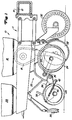
- FIG. 1 shows an agricultural row planting unit 10.
- This row planting unit 10 is in the conventional manner U-brackets 14 with a parallel link system 11 to a cross extending tool carrier 12 connected.
- the row planting unit 10 is provided with a seed box 16 which Seed feeds a metering device 18.
- the metering device 18 conducts the metered seed into a seed tube 20 to put it in a seed furrow store.
- the seed furrow is opened by means of a furrow opener 22 educated.
- Adjustment wheels 24 determine the depth of penetration of the Furrow opener 22.
- a pair of pressure wheels 26 for compressing the Soil and seed closes the cut or furrow after the seed into the furrow by means of the sowing tube 20 has been filed.
- the row planting unit 10 shown is also with a reservoir 28 for Provide pesticide from where pesticide to the floor by means of an output unit 30 is delivered.
- a suitable pesticide metering device, not shown controls the spreading of the Pesticides.
- the aforementioned row planting unit 10 is relative conventional design. Typically, a variety of Row planting units 10 attached to the tool carrier 12, so that a farmer can sow or plant more than one row, while driving across the field once. Although the present Invention in connection with a row planting unit 10 is shown and described, it can also with a Seeding unit, e.g. B. a seeder can be used, d. i.e. the Protection should not be on a planting unit or planting machine be restricted.
- a Seeding unit e.g. B.
- a seeder can be used, d. i.e. the Protection should not be on a planting unit or planting machine be restricted.
- the pressure wheels 26 are rotatably attached to a holder 34, which is itself attached to a wheel carrier 36.
- the holder 34 is provided with a handle 38 that can be adjusted to the measure of soil pressure from row planting unit 10 the pressure wheels 26 is transmitted to control.
- the handle 38 is connected to a spring 40, which is also a downward extending tab 42 on the wheel carrier 36 connected.
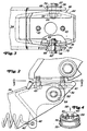
- the details of the wheel carrier 36 are on best shown in Figures 2 to 4.
- the wheel carrier 36 is a casting, which by means of screws 43 to the row planting unit 10 is screwed.
- the wheel carrier 36 has a left and one right side wall 44 and 46, the left and right respectively have curved surfaces 48 and 50 respectively. In addition, they are left and right side walls 44, 46 along with each other extending slots 52 provided.
- the holder 34 has a left and a right curved Bearing sleeve 56 or 58. Curved surfaces 59 of the bearing sleeves 56, 58 touch the curved surfaces 48, 50 of the wheel carrier 36.
- the bearing sleeves 56, 58 are also with two semicircular Provide projections 60 which in the longitudinally extending Slits 52 are added.
- Two adjusting screws 62 with Nuts 64 are used to secure the bracket 34 to the wheel carrier 36 set. These screws 62 extend through the Bearing sleeves 56 and 58 and through the longitudinally extending Slits 52 and are secured in position by means of the nuts 64.
- each Bearing sleeve 56, 58 contains a cylindrical body 70 with an outwardly extending shoulder 72 outside shoulder 72 is on the outside of the Side walls 44, 46 of the holder 34, as shown in FIG. 3 is shown.
Landscapes
- Life Sciences & Earth Sciences (AREA)
- Soil Sciences (AREA)
- Environmental Sciences (AREA)
- Sowing (AREA)
- Soil Working Implements (AREA)
Description
- Fig. 1
- eine erfindungsgemäße Reihenpflanzeinheit mit einer Vorrichtung zum Andrücken des Erdreichs in Seitenansicht,
- Fig. 2
- einen Ausschnitt der Vorrichtung in Draufsicht,
- Fig. 3
- den Ausschnitt aus Figur 2 in Seitenansicht und
- Fig. 4
- eine in der Vorrichtung verwendete Lagerhülse in perspektivischer Darstellung.
Claims (8)
- Vorrichtung zum Einstellen von wenigstens einem Andrückrad (26), das drehbar von einem Halter (34) getragen wird, der um eine vertikale Achse schwenkbar an einem Geräterahmen (33) einer Sä- oder Pflanzmaschine angelenkt und in einer einstellbaren Position bezüglich der vertikalen Achse am Geräterahmen (33) festlegbar ist, dadurch gekennzeichnet, daß der Geräterahmen (33) mit wenigstens einer gewölbten Oberfläche (48, 50) an einer Seitenwand (44, 46) versehen ist, an der der Halter (34) mittelbar oder unmittelbar zur Anlage bringbar ist und die Drehachse des Andrückrades (26) einen horizontalen Abstand zu der Anschlußstelle des Halters (34) an dem Geräterahmen (33) aufweist.
- Vorrichtung nach Anspruch 1, dadurch gekennzeichnet, daß der Halter (34) mittels wenigstens einer eine entsprechend gewölbte Fläche (59) aufweisenden Lagerbüchse (56, 58) an dem Geräterahmen (33) festlegbar ist.
- Vorrichtung nach einem oder mehreren der vorherigen Ansprüche, dadurch gekennzeichnet, daß zur Festlegung der Lagerbüchse (56, 58) an den Seitenwänden (44, 46) des Geräterahmens (33) wenigstens eine sich durch sie erstreckende Einstellschraube (62) vorgesehen ist.
- Vorrichtung nach einem oder mehreren der vorherigen Ansprüche, dadurch gekennzeichnet, daß in den Seitenwänden (44, 46) wenigstens ein Schlitz (52) zur Aufnahme der Einstellschraube(n) (62) vorgesehen ist.
- Vorrichtung nach einem oder mehreren der vorherigen Ansprüche, dadurch gekennzeichnet, daß die Lagerhülse (56, 58) mit halbkreisförmigen Vorsprüngen (60) versehen ist, die gleitend von dem Schlitz (52) aufgenommen werden.
- Vorrichtung nach einem oder mehreren der vorherigen Ansprüche, gekennzeichnet durch eine spiegelbildliche Anordnung der gewölbten Oberflächen (48, 50) an dem Halter (34), der Lagerhülsen (56, 58) und zweier Andrückräder (26).
- Reihenpflanzeinheit (10) mit einem Geräterahmen (33) zur Aufnahme eines Furchenöffners (22), eines Särohrs (20) und eines wenigstens ein Andrückrad (26) tragenden Halters (34), wobei der Halter (34) mittels einer Vorrichtung nach einem oder mehreren der vorherigen Ansprüche 1 bis 7 an dem Geräterahmen (33) angebracht ist.
- Reihenpflanzeinheit (10) nach Anspruch 7, dadurch gekennzeichnet, daß zwei Andrückräder (26) vorgesehen sind, die die Furche mittig zwischen sich aufnehmen und vorzugsweise V-förmig zueinander ausgerichtet sind.
Applications Claiming Priority (2)
| Application Number | Priority Date | Filing Date | Title |
|---|---|---|---|
| US636046 | 1990-12-31 | ||
| US08/636,046 US5676073A (en) | 1996-04-22 | 1996-04-22 | Closing wheels adjustment mechanism |
Publications (2)
| Publication Number | Publication Date |
|---|---|
| EP0803176A1 EP0803176A1 (de) | 1997-10-29 |
| EP0803176B1 true EP0803176B1 (de) | 2003-03-19 |
Family
ID=24550183
Family Applications (1)
| Application Number | Title | Priority Date | Filing Date |
|---|---|---|---|
| EP97105667A Expired - Lifetime EP0803176B1 (de) | 1996-04-22 | 1997-04-05 | Vorrichtung zum Einstellen von wenigstens einem Andrückrad und Reihenpflanzeinheit mit einer solchen Vorrichtung |
Country Status (7)
| Country | Link |
|---|---|
| US (1) | US5676073A (de) |
| EP (1) | EP0803176B1 (de) |
| AR (1) | AR006457A1 (de) |
| BR (1) | BR9701903A (de) |
| CA (1) | CA2200092C (de) |
| DE (1) | DE59709533D1 (de) |
| ES (1) | ES2195046T3 (de) |
Families Citing this family (11)
| Publication number | Priority date | Publication date | Assignee | Title |
|---|---|---|---|---|
| US5960721A (en) * | 1998-05-20 | 1999-10-05 | Teh Marathon Pallet Trust | Composite wood and polymer forklift pallet assembly and method |
| US6918343B2 (en) * | 2002-05-08 | 2005-07-19 | Philip C. Kester | Pivot assembly for planter closing wheel frame |
| US7975629B1 (en) | 2008-06-06 | 2011-07-12 | Martin Ronald S | Closing wheel assembly |
| WO2012167244A1 (en) | 2011-06-03 | 2012-12-06 | Precision Planting, Inc. | Agricultural row unit apparatus, systems, and methods |
| WO2014066650A1 (en) * | 2012-10-24 | 2014-05-01 | Precision Planting Llc | Agricultural trench closing systems, methods, and apparatus |
| US9699954B2 (en) * | 2015-06-30 | 2017-07-11 | Cnh Industrial America Llc | Adjustable down stop for agricultural closing discs |
| US10154621B2 (en) | 2016-01-15 | 2018-12-18 | Shoup Manufacturing Co., Inc. | Free-floating laterally adustable gauge wheel arm |
| CA2992281C (en) | 2016-03-08 | 2020-08-18 | Harvest International, Inc. | Quick change closing wheel assembly with centering adjustment |
| US10299427B2 (en) | 2016-04-22 | 2019-05-28 | Harvest International, Inc. | Row planter with adjustable gauge wheels |
| US11357161B2 (en) | 2018-12-07 | 2022-06-14 | Harvest International, Inc. | Gauge wheel arm with split end and threaded bore |
| US12102029B2 (en) | 2021-06-24 | 2024-10-01 | Cnh Industrial Canada, Ltd. | Adjustable wedge assembly for changing angle on disk drill closing wheel |
Family Cites Families (14)
| Publication number | Priority date | Publication date | Assignee | Title |
|---|---|---|---|---|
| US757999A (en) * | 1903-04-09 | 1904-04-19 | Oliver Chilled Plow Works | Lister plow and planter. |
| US1040049A (en) * | 1911-10-05 | 1912-10-01 | William J Steele | Plow attachment. |
| US1165735A (en) * | 1915-02-15 | 1915-12-28 | William Wentz | Packing-wheel for listers. |
| US1901299A (en) * | 1932-02-06 | 1933-03-14 | Edward E Greiner | Mulching wheel for seeding machines |
| FR1170523A (fr) * | 1957-04-01 | 1959-01-15 | Perfectionnements aux porte-disques, notamment pour semoirs, etc. | |
| DE1295260B (de) * | 1964-01-28 | 1969-05-14 | Troester A J | Scheibenschar fuer Drillmaschinen |
| US3719158A (en) * | 1968-02-14 | 1973-03-06 | H Roths | Transplanting machine |
| US4009668A (en) * | 1975-07-07 | 1977-03-01 | Deere & Company | Planter apparatus and method for planting |
| US4404918A (en) * | 1981-09-14 | 1983-09-20 | Yetter Manufacturing Co. | Closing wheel mounting for a planter |
| AU3261384A (en) * | 1983-10-28 | 1985-05-02 | Deere & Company | Closing system cam alignment for planter row units |
| US4570554A (en) * | 1983-10-28 | 1986-02-18 | Deere & Company | Adjustable width closing wheels for planter row units |
| US5375542A (en) * | 1993-04-20 | 1994-12-27 | Schaffert; Paul E. | Seed covering apparatus |
| US5394946A (en) * | 1993-06-16 | 1995-03-07 | Deere & Company | Row cleaning attachment |
| US5542774A (en) * | 1994-12-08 | 1996-08-06 | Hoy; David J. | Orthotic joint |
-
1996
- 1996-04-22 US US08/636,046 patent/US5676073A/en not_active Expired - Lifetime
-
1997
- 1997-03-14 CA CA002200092A patent/CA2200092C/en not_active Expired - Fee Related
- 1997-03-31 AR ARP970101280A patent/AR006457A1/es unknown
- 1997-04-05 EP EP97105667A patent/EP0803176B1/de not_active Expired - Lifetime
- 1997-04-05 ES ES97105667T patent/ES2195046T3/es not_active Expired - Lifetime
- 1997-04-05 DE DE59709533T patent/DE59709533D1/de not_active Expired - Fee Related
- 1997-04-22 BR BR9701903A patent/BR9701903A/pt not_active IP Right Cessation
Also Published As
| Publication number | Publication date |
|---|---|
| AR006457A1 (es) | 1999-08-25 |
| BR9701903A (pt) | 1998-11-10 |
| DE59709533D1 (de) | 2003-04-24 |
| CA2200092A1 (en) | 1997-10-22 |
| US5676073A (en) | 1997-10-14 |
| CA2200092C (en) | 2000-05-23 |
| EP0803176A1 (de) | 1997-10-29 |
| ES2195046T3 (es) | 2003-12-01 |
| MX9702592A (es) | 1997-10-31 |
Similar Documents
| Publication | Publication Date | Title |
|---|---|---|
| DE2140410C3 (de) | An ein ziehendes Fahrzeug anschließbare Sämaschine | |
| DE10311796B4 (de) | Aussaatelement | |
| EP0811311B1 (de) | Furchenöffner und Pflanzeinheit mit einem Furchenöffner | |
| EP0140190A2 (de) | Sämaschine | |
| EP2335465B1 (de) | Landmaschine | |
| EP0803176B1 (de) | Vorrichtung zum Einstellen von wenigstens einem Andrückrad und Reihenpflanzeinheit mit einer solchen Vorrichtung | |
| DE4123854A1 (de) | Geschlossene duengerverteil- und saekombination | |
| EP1974596B1 (de) | Säscharanordnung | |
| DE2310805A1 (de) | Saemaschine | |
| DE3425194A1 (de) | Walzenpflug | |
| DE2634688A1 (de) | Kombinationsmaschine zur bodenbearbeitung sowie zum ablegen von saat und/oder duengemitteln | |
| DE102007011297B4 (de) | Gezogene Säscharanordnung | |
| DE69420316T2 (de) | Sämaschine mit einer Vorrichtung zur Begrenzung der Tiefe von Säscharen im Boden, und eine kombinierte Landmaschine bestehend aus einer Bodenbearbeitungsmaschine und eine Sämaschine mit Verwendung einer solcher Sämaschine | |
| DE3627801A1 (de) | Drillmaschine | |
| DE60315831T2 (de) | Landmaschine | |
| DE3633685A1 (de) | Saemaschine | |
| EP0313834B2 (de) | Drillmaschine | |
| EP0264621A1 (de) | Landwirtschaftliche Gerätekombination | |
| EP3515167A1 (de) | Sämaschine zum ausbringen von saatgut und/oder dünger | |
| WO1997016060A9 (de) | Drillmaschine mit stellvorrichtung für säschar und druckrolle | |
| DE4330555C2 (de) | Direktsämaschine | |
| EP0203223B1 (de) | Sämaschine mit unter Federandruckkraft stehenden Säscharen | |
| DE69406958T2 (de) | Anordnung für die Scharen einer Sämaschine | |
| DE69407113T2 (de) | Pneumatischer Sämaschine und kombinierte Landmaschine zur Bodenbearbeitung und zum Säen mit einer solchen pneumatischen Sämaschine | |
| DE3786982T2 (de) | Bestellgerätekombination. |
Legal Events
| Date | Code | Title | Description |
|---|---|---|---|
| PUAI | Public reference made under article 153(3) epc to a published international application that has entered the european phase |
Free format text: ORIGINAL CODE: 0009012 |
|
| AK | Designated contracting states |
Kind code of ref document: A1 Designated state(s): DE ES FR IT |
|
| 17P | Request for examination filed |
Effective date: 19980312 |
|
| 17Q | First examination report despatched |
Effective date: 20010727 |
|
| GRAG | Despatch of communication of intention to grant |
Free format text: ORIGINAL CODE: EPIDOS AGRA |
|
| GRAG | Despatch of communication of intention to grant |
Free format text: ORIGINAL CODE: EPIDOS AGRA |
|
| GRAH | Despatch of communication of intention to grant a patent |
Free format text: ORIGINAL CODE: EPIDOS IGRA |
|
| RAP1 | Party data changed (applicant data changed or rights of an application transferred) |
Owner name: DEERE & COMPANY |
|
| GRAH | Despatch of communication of intention to grant a patent |
Free format text: ORIGINAL CODE: EPIDOS IGRA |
|
| GRAA | (expected) grant |
Free format text: ORIGINAL CODE: 0009210 |
|
| AK | Designated contracting states |
Designated state(s): DE ES FR IT |
|
| REF | Corresponds to: |
Ref document number: 59709533 Country of ref document: DE Date of ref document: 20030424 Kind code of ref document: P |
|
| ET | Fr: translation filed | ||
| PLBE | No opposition filed within time limit |
Free format text: ORIGINAL CODE: 0009261 |
|
| STAA | Information on the status of an ep patent application or granted ep patent |
Free format text: STATUS: NO OPPOSITION FILED WITHIN TIME LIMIT |
|
| 26N | No opposition filed |
Effective date: 20031222 |
|
| PGFP | Annual fee paid to national office [announced via postgrant information from national office to epo] |
Ref country code: DE Payment date: 20090319 Year of fee payment: 13 |
|
| PG25 | Lapsed in a contracting state [announced via postgrant information from national office to epo] |
Ref country code: DE Free format text: LAPSE BECAUSE OF NON-PAYMENT OF DUE FEES Effective date: 20101103 |
|
| PGFP | Annual fee paid to national office [announced via postgrant information from national office to epo] |
Ref country code: FR Payment date: 20140417 Year of fee payment: 18 Ref country code: ES Payment date: 20140428 Year of fee payment: 18 Ref country code: IT Payment date: 20140430 Year of fee payment: 18 |
|
| PG25 | Lapsed in a contracting state [announced via postgrant information from national office to epo] |
Ref country code: IT Free format text: LAPSE BECAUSE OF NON-PAYMENT OF DUE FEES Effective date: 20150405 |
|
| REG | Reference to a national code |
Ref country code: FR Ref legal event code: ST Effective date: 20151231 |
|
| PG25 | Lapsed in a contracting state [announced via postgrant information from national office to epo] |
Ref country code: FR Free format text: LAPSE BECAUSE OF NON-PAYMENT OF DUE FEES Effective date: 20150430 |
|
| REG | Reference to a national code |
Ref country code: ES Ref legal event code: FD2A Effective date: 20160527 |
|
| PG25 | Lapsed in a contracting state [announced via postgrant information from national office to epo] |
Ref country code: ES Free format text: LAPSE BECAUSE OF NON-PAYMENT OF DUE FEES Effective date: 20150406 |