EP0803003B1 - Apparatus for steam fixing of stockings and similar articles - Google Patents
Apparatus for steam fixing of stockings and similar articles Download PDFInfo
- Publication number
- EP0803003B1 EP0803003B1 EP95939373A EP95939373A EP0803003B1 EP 0803003 B1 EP0803003 B1 EP 0803003B1 EP 95939373 A EP95939373 A EP 95939373A EP 95939373 A EP95939373 A EP 95939373A EP 0803003 B1 EP0803003 B1 EP 0803003B1
- Authority
- EP
- European Patent Office
- Prior art keywords
- case
- molds
- closing
- fit
- steam
- Prior art date
- Legal status (The legal status is an assumption and is not a legal conclusion. Google has not performed a legal analysis and makes no representation as to the accuracy of the status listed.)
- Expired - Lifetime
Links
- 238000007789 sealing Methods 0.000 claims abstract description 7
- 238000012856 packing Methods 0.000 claims description 11
- 238000001035 drying Methods 0.000 description 5
- 230000002950 deficient Effects 0.000 description 3
- 230000007547 defect Effects 0.000 description 2
- 239000011521 glass Substances 0.000 description 2
- 238000011068 loading method Methods 0.000 description 2
- 150000001875 compounds Chemical class 0.000 description 1
- 238000009833 condensation Methods 0.000 description 1
- 230000005494 condensation Effects 0.000 description 1
- 230000003247 decreasing effect Effects 0.000 description 1
- 239000006185 dispersion Substances 0.000 description 1
- 239000013013 elastic material Substances 0.000 description 1
- 238000000605 extraction Methods 0.000 description 1
- 239000004744 fabric Substances 0.000 description 1
- 238000004519 manufacturing process Methods 0.000 description 1
- 238000012986 modification Methods 0.000 description 1
- 230000004048 modification Effects 0.000 description 1
- 230000010355 oscillation Effects 0.000 description 1
- 238000010422 painting Methods 0.000 description 1
- 230000002093 peripheral effect Effects 0.000 description 1
- 238000003825 pressing Methods 0.000 description 1
- 238000003672 processing method Methods 0.000 description 1
- 238000007493 shaping process Methods 0.000 description 1
- 239000007787 solid Substances 0.000 description 1
- 238000007669 thermal treatment Methods 0.000 description 1
- 238000011144 upstream manufacturing Methods 0.000 description 1
- 239000002699 waste material Substances 0.000 description 1
- XLYOFNOQVPJJNP-UHFFFAOYSA-N water Substances O XLYOFNOQVPJJNP-UHFFFAOYSA-N 0.000 description 1
Images

Classifications
-
- D—TEXTILES; PAPER
- D06—TREATMENT OF TEXTILES OR THE LIKE; LAUNDERING; FLEXIBLE MATERIALS NOT OTHERWISE PROVIDED FOR
- D06C—FINISHING, DRESSING, TENTERING OR STRETCHING TEXTILE FABRICS
- D06C5/00—Shaping or stretching of tubular fabrics upon cores or internal frames
- D06C5/005—Shaping or stretching of tubular fabrics upon cores or internal frames of articles, e.g. stockings
-
- D—TEXTILES; PAPER
- D06—TREATMENT OF TEXTILES OR THE LIKE; LAUNDERING; FLEXIBLE MATERIALS NOT OTHERWISE PROVIDED FOR
- D06C—FINISHING, DRESSING, TENTERING OR STRETCHING TEXTILE FABRICS
- D06C7/00—Heating or cooling textile fabrics
- D06C7/02—Setting
Definitions
- the present invention relates to the technical field concerned with the apparatuses for treating of stockings.
- the present invention relates to an apparatus for steam fixing of woman stockings, like tights or the like.
- Apparatuses for controlling, fixing and drying of stockings are known, which generally comprise a rotating turret, able to transport subsequently the stockings to be treated up to the various operating stations, comprising a stockings inserting station and a stocking extraction station.
- Stockings are inserted on suitable molds, which are usually constituted by curved tubular elements, defining the stockings profile. Moulds are held at the rotating turret periphery, being regularly spaced.
- the fixing phase is achieved by introducing molds inside a chamber, which is fed with water steam and where the fabric is submitted to a permanent shaping.
- Patent N. 1225876 shows, by example, a fixing apparatus in which the steam chamber has opposite lateral walls, one of which is fixed, and the other one is movable to allow the chamber to be closed, for introducing the steam, and then the chamber to be opened, thus allowing molds to be moved.
- pressing pads are mounted, fit to engage and to compress stockings on their molds, when the steam chamber is in its closed position.
- the apparatus comprises a double steam chamber fit to receive, while in an open position, respective pairs of molds.
- Said steam chamber is made of two symmetrically movable shells, fit to be sealingly coupled at their respective front edges; the cited shells, when in their closed position, have internal walls which cling to the moulds.
- the GB-A-2138856 discloses a hosiery processing method and apparatus.
- the apparatus includes a support frame with a plurality of hosiery carrying forms supported by a driving chain mechanism.
- a flat steam chamber includes a stationary wall and a movable wall both having peripheral seals. The movable wall can be moved toward and away from the stationary wall to open and close the steam chamber.
- the hosiery carrying frames are held stationary temporarily at the steam chamber while steam is injected in the chamber and the movable wall is moved to close the chamber and set the fibres of the hosiery.
- opening the fixing chamber walls causes a sudden drop in temperature, so providing evident problems due to condensation forming, together to a steam dispersion.
- the last fact causes some energy wasting, and makes the working environment less comfortable.
- a further drawback is due to the high amount of time the moulds stay into the steam chamber. In fact, that time affects the cycle rate of the others operating phases, which are usually faster; increasing that time means reducing the apparatus productivity. On the opposite side, reducing the fixing time below a threshold value compromises the success of thermal treatment.
- an apparatus for steam fixing of stockings or similar articles which comprises a case (17), internally defining a steam chamber (18), having a flattened shape along a longitudinal plane coincident with a forwarding plane for moulds (2) which are upwardly supported and oriented downwardly, the said case (17) being provided, at its entrance and at its exit, of closing doors (19), and being also provided, at its upper part, with a longitudinal slit (21), fit to allow said molds (2) to pass along the said steam chamber (18), said slit (21) being also fit to be closed around the molds (2) by sealing means (22).
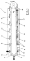
- 1 indicates an apparatus for controlling, steam fixing and drying of woman stockings, of the type of tights or the like.
- Apparatus 1 carries and moves in an intermittent way, according to a ring path, a series of molds 2, arranged in pairs and fit to inserting on each of them corresponding stockings to be treated. Molds 2 are made of suitably shaped solid glass bodies.
- molds 2 have a flattened shape, and an outline getting narrower towards their free end, which substantially corresponds to the stockings feet.
- Molds 2 are turned downwardly, in order to allow stockings to be inserted from down upwards, and they are held upwardly, by means of respective stems 3, by a pair of chains 4, defining the said ring path.
- the ring path extends along a longitudinal direction defined by a fixed frame 5.
- the chains 4 wrap around a pulley 6 at one end of the frame 5, and around a corresponding pair of reels at the opposite end of the same frame 5.
- Pulley 6 is operated by an engine member 8, for intermittently forward the molds 2.
- Operating the engine 8 allows to move the molds 2 successively to a station 9 for loading the stockings to be treated; to a station 10 for controlling said stockings for defects; to first station 11 and to a second station 12 for discarding defective stockings; to a station 13 for fixing the non-defective stockings into a suitable steam chamber; to a drying station 14; and finally to a station 15 for extracting stockings and for driving away them.
- the pairs of molds 2 are suitably rotatable, one with respect to each other, about a hinging pivot 16, so that one of the molds can go near the other one. Said rotation is made with known means, not shown in the drawings, downstream of the said drying station 14, to allow the subsequent extracting operation of stockings in the station 15.
- Molds 2 are carried back to their spreaded position upstream of the loading station 9.
- the fixing station 13 is provided with a case 17, defining the steam chamber 18.
- the case 17 has a shape which is flattened about a longitudinal plane coinciding with the molds 2 forwarding plane.
- the case 17 is provided, at the entrance and at the exit of the steam chamber 18, with closing doors 19, sideways hinged about pivots 20 having vertical axis.
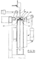
- the molds 2 pass through a longitudinal slit 21 made on the upper wall of the case 17 (see Fig. 3a).
- the slit 21 is fit to be closed, around the molds 2, by a pair of bulkheads 22, which are hinged about respective shafts 23, longitudinally mounted sideways of the case 17; bulkheads 22 can swing, respectly driven by a first jack 24 and by a second jack 25, by means of respective compound levers 26,27.
- Each one of the bulkheads 22 carries a pair of packings 28,29, extending longitudinally with respect to the said bulkheads 22 and arranged on perpendicular faces of the same, which respectively constitute a bottom face and a side face when they are in a configuration closing the slit 21 (see Fig. 3b).
- Bottom packings 28 are fit to make a seal by contact with the said upper wall of the case 17, while the side packings 29 make a seal by respectively contacting one each other. (see Fig. 3b).
- packings 28,29 are made of elastic material, so that they can wrap around molds 2 passing through the slit 21, thus making a seal with the said molds 2.
- An optimum seal of packings 28,29 on molds 2 is achieved because the said molds 2 are made of glass, and because they are moistened by the steam contained into the fixing chamber 18.
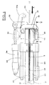
- doors 19 are integral with arms 31, hinged on the above mentioned pivots 20; on each door 19 at least two closing arms 31 are provided; they are swingly mounted on suitably spaced horizontal planes.
- Each of the closing arms 31 is bended, by means of an appendage 32, to the stem 33 of a respective jack 34, which is hinged, in its turn, sideways of the case 17.
- the jack 34 operates the rotation of arms 31 between the door 19 opening position, which is indicated with a dashed line 31a in Fig. 4, and a closing position.
- clamping members 35 of the doors 19 are provided, fit to ensure a suitable closing force for pressure sealing the fixing chamber.
- the clamping members 35 comprise a latch 36, which is driven for vertically sliding over rails 37, on a side of the case 17, and which is operated with a reciprocating motion by means of an actuating member 38, the latter being fixed to the same case 17.
- the latch 36 is provided with two protruding, conical-ended pivots 39, placed at suitable heights and vertically coaxial. Pivots 39 are fit to engage, when in the clamping position, corresponding vertical holes 40, made on the closing arms 31; when in said position, they force the closing of the closing arms 31 by means of their conical end.
- the chamber 18 is fit to be fed with steam by means of a known system, in order to perform the fixing of stockings carried by molds 2 inside the same chamber 18.
- the jacks 34 open the doors 19 by operating the arms 31, which are rotated to their opening position 31a (see Fig. 4) while, at the same time, jacks 24,25 rotate the bulkheads 22 to the opening position 22a of slit 21, being said position raised from the case 17 (see Fig. 3a).
- molds 2 proceed on a plane which is vertical and longitudinally median with respect to the case 17, in the direction which has been indicated with an arrow A.
- the position reached by a mold at the entrance of the case 17 has been indicated with 2a.
- Molds 2 pass through the slit 21 placed on the upper side of the case 17.
- Opening the steam chamber 18 is made in the opposite way, at the end of the fixing phase, in order to allow the molds 2 to be moved forward.
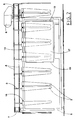
- the fixing chamber 18 extends straightly and longitudinally with respect to the forwarding direction of molds 2. This allows multiple pairs of molds 2 to be inserted into the fixing chamber 18, e.g. three pairs of molds 2, as shown in Figures 1 and 2.
- Another advantage due to the straight arrangement of the fixing chamber 18 is that molds 2 are not subject, during their forwarding, to any centrifugal force, which could cause some kind of molds oscillations; thus, there is no risk for stockings to be damaged by touching the internal walls of the fixing chamber 18.
- the fixing chamber 18 is of very small size, particularly in its width, which is only large enough to arrange the molds 2. It is to be noted that all the chamber 18 closing members and all the molds 2 moving members are placed externally with respect to the case 17.
- a very important feature of the fixing apparatus of the present invention is that the case 17 defining the steam chamber 18 is substantially closed for the whole operating cycle.
- the case 17 is opened only at its entrance and exit doors 19, and at the slit 21, for a short period of time, which is enough to allow the molds 2 to come in to, and to go cut from, the fixing chamber 18.
Landscapes
- Engineering & Computer Science (AREA)
- Textile Engineering (AREA)
- Treatment Of Fiber Materials (AREA)
- Socks And Pantyhose (AREA)
- Treatments For Attaching Organic Compounds To Fibrous Goods (AREA)
Abstract
Description
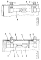
- Figure 1 shows a schematic plain view of an apparatus for treating woman stockings, of the tights type;
- Figure 2 shows a side view of the apparatus of figure 1;
- Figures 3a and 3b show a vertical section view of the fixing station of the above mentioned apparatus, in various operating phases;
- Figure 4 shows a partial upper view of said fixing station;
- Figures 5a and 5b show a view of a detail of said fixing station, according to the section plane V-V of Figure 4, in various operating phases.
Claims (7)
- Apparatus for steam fixing of stockings or similar articles; characterized in that it comprises a case (17), internally defining a steam chamber (18), having a flattened shape along a longitudinal plane coincident with a forwarding plane for moulds (2), which are upwardly supported and oriented downwardly, the said case (17) being provided, at its entrance and at its exit, of closing doors (19), and being also provided, at its upper part, with a longitudinal slit (21), fit to allow said molds (2) to pass along the said steam chamber (18), said slit (21) being also fit to be closed around the molds (2) by sealing means (22).
- Apparatus according to Claim 1, characterized in that the said sealing means (22) have a pair of bulkheads; able to swing about respective longitudinal axes, said bulkheads being mounted on opposite sides of the said case (17), being operable by reciprocating actuating means (24,25) and being provided with packings (28,29) extending longitudinally for sealingly closing said slit (21).
- Apparatus according to Claim 2, characterized in that the said packings (28,29) are placed on respectively perpendicular walls of said bulkheads (22), forming the lower and side walls of the same when they are in a position closing the said slit (21), being the said lower packings (28) fit to sealingly engage the upper wall of said case (17), and being the said side packings (29) fit to sealingly engage one each other.
- Apparatus according to Claim 1, characterized in that said doors (19) are fixed to closing arms (31). hinged to the said case (17) on vertical pivots (20), able to swing driven by reciprocating actuating means (34), which are fit to rotate the above mentioned arms (31) for moving the said doors (19) between an opening position and a closing position.
- Apparatus according to Claim 1, characterized in that it comprises clamping members (35) for clamping said doors (19), each one of whose members is provided with a latch (36), vertically slidable on one side of said case (17) and reciprocably operated by means of an actuating member (38), restrained to the same case (17), said latch (36) carrying at least one protruding vertical pivot (39) fit to engage, when in the clamping position, a corresponding hole (40), vertically made in a closing arm (31) of a respective door (19).
- Apparatus according to Claim 5, characterized in that said latches (26) carry a pair of said protruding pivots (39), placed at a suitable heigth, each one of whose being provided with a conical end, and being arranged coaxially on a vertical axis and fit to engage, when in the clamping position, corresponding holes (40), vertically made in respective closing arms (31) of said doors (19), thus forcing their closing by means of said conical ends.
- Apparatus according to Claim 1, characterized in that the said case (17) extends straightly, in order to allow the concurrent arrangement of a plurality of molds (2) pairs inside the said chamber (18) during the fixing phase.
Applications Claiming Priority (3)
| Application Number | Priority Date | Filing Date | Title |
|---|---|---|---|
| ITBO940566 | 1994-12-21 | ||
| ITBO940566A IT1274143B (en) | 1994-12-21 | 1994-12-21 | EQUIPMENT FOR STEAM FIXING OF STOCKINGS AND SIMILAR |
| PCT/IB1995/001147 WO1996019609A1 (en) | 1994-12-21 | 1995-12-20 | Apparatus for steam fixing of stockings and similar articles |
Publications (2)
| Publication Number | Publication Date |
|---|---|
| EP0803003A1 EP0803003A1 (en) | 1997-10-29 |
| EP0803003B1 true EP0803003B1 (en) | 1999-04-14 |
Family
ID=11340169
Family Applications (1)
| Application Number | Title | Priority Date | Filing Date |
|---|---|---|---|
| EP95939373A Expired - Lifetime EP0803003B1 (en) | 1994-12-21 | 1995-12-20 | Apparatus for steam fixing of stockings and similar articles |
Country Status (5)
| Country | Link |
|---|---|
| EP (1) | EP0803003B1 (en) |
| AT (1) | ATE178960T1 (en) |
| DE (1) | DE69509133D1 (en) |
| IT (1) | IT1274143B (en) |
| WO (1) | WO1996019609A1 (en) |
Families Citing this family (2)
| Publication number | Priority date | Publication date | Assignee | Title |
|---|---|---|---|---|
| ITBO20010214A1 (en) * | 2001-04-11 | 2002-10-11 | Cortese Spa | METHOD AND MACHINE FOR FIXING TEXTILE ITEMS |
| ITPI20010093A1 (en) * | 2001-12-21 | 2003-06-21 | Matec Spa | METHOD AND EQUIPMENT PERFECTED FOR IRONING ON SHAPES OF FOOTWEAR ITEMS |
Family Cites Families (2)
| Publication number | Priority date | Publication date | Assignee | Title |
|---|---|---|---|---|
| US4524889A (en) * | 1983-04-28 | 1985-06-25 | Intech Corporation | Hosiery processing method |
| JPH03124873A (en) * | 1989-10-03 | 1991-05-28 | Takatori Haitetsuku:Kk | Device for finishing hosiery |
-
1994
- 1994-12-21 IT ITBO940566A patent/IT1274143B/en active IP Right Grant
-
1995
- 1995-12-20 EP EP95939373A patent/EP0803003B1/en not_active Expired - Lifetime
- 1995-12-20 AT AT95939373T patent/ATE178960T1/en not_active IP Right Cessation
- 1995-12-20 WO PCT/IB1995/001147 patent/WO1996019609A1/en not_active Ceased
- 1995-12-20 DE DE69509133T patent/DE69509133D1/en not_active Expired - Lifetime
Also Published As
| Publication number | Publication date |
|---|---|
| ATE178960T1 (en) | 1999-04-15 |
| ITBO940566A0 (en) | 1994-12-21 |
| ITBO940566A1 (en) | 1996-06-21 |
| WO1996019609A1 (en) | 1996-06-27 |
| DE69509133D1 (en) | 1999-05-20 |
| IT1274143B (en) | 1997-07-15 |
| EP0803003A1 (en) | 1997-10-29 |
Similar Documents
| Publication | Publication Date | Title |
|---|---|---|
| US5094371A (en) | Finishing device for stockings hose | |
| US4683028A (en) | Moulding | |
| EP0803003B1 (en) | Apparatus for steam fixing of stockings and similar articles | |
| US4519327A (en) | Transfer machine for overturning a textile tubular element for the sewing of the edges thereof and for the subsequent re-overturning and discharging | |
| JP3656521B2 (en) | Method and apparatus for processing natural intestinal sausage terminals | |
| EP0766922B1 (en) | An inverter device for moulds | |
| US4524889A (en) | Hosiery processing method | |
| US6052916A (en) | Automatic plant for pressing and unloading articles of clothing | |
| KR100339989B1 (en) | A method for cutting a lying bar-shaped food and the same apparatus | |
| EP0652319A1 (en) | Machine for treating socks with a well-defined heel | |
| JPH11348101A (en) | Automatic setting method of stretch rod position and its device | |
| US6155466A (en) | Apparatus for stretching apart one end of a tubular article | |
| US4412434A (en) | Apparatus for the dyeing and fixing of knitted articles of clothing | |
| JPH07300766A (en) | Machine for management and molding of stockings and tights | |
| EP1325975A2 (en) | Method and apparatus for steaming on forms hosiery articles and the like | |
| EP0889986B1 (en) | Drying method and associated apparatus in a plant for checking and stretching knitted articles | |
| KR0140579B1 (en) | Method and apparatus for folding pockets in garments | |
| US3214792A (en) | Apparatus for the vulcanization of articles made of rubber or like material | |
| CN217624501U (en) | Dried egg baling line monitoring device | |
| CN219339826U (en) | Full-automatic stretch film vacuum packaging machine | |
| IT9021506A1 (en) | EQUIPMENT AND PROCEDURE FOR WASHING ARTICLES. | |
| CN117071225A (en) | A steam setting equipment for sports socks production line | |
| JP3478362B2 (en) | Nori production method and apparatus | |
| CN119564891A (en) | A fabric disinfection and sterilization device for clothing production | |
| CN212707830U (en) | Exhaust structure of injection mold |
Legal Events
| Date | Code | Title | Description |
|---|---|---|---|
| PUAI | Public reference made under article 153(3) epc to a published international application that has entered the european phase |
Free format text: ORIGINAL CODE: 0009012 |
|
| 17P | Request for examination filed |
Effective date: 19970722 |
|
| AK | Designated contracting states |
Kind code of ref document: A1 Designated state(s): AT BE CH DE ES FR GB GR IE IT LI PT |
|
| 17Q | First examination report despatched |
Effective date: 19980331 |
|
| GRAG | Despatch of communication of intention to grant |
Free format text: ORIGINAL CODE: EPIDOS AGRA |
|
| GRAG | Despatch of communication of intention to grant |
Free format text: ORIGINAL CODE: EPIDOS AGRA |
|
| GRAH | Despatch of communication of intention to grant a patent |
Free format text: ORIGINAL CODE: EPIDOS IGRA |
|
| GRAH | Despatch of communication of intention to grant a patent |
Free format text: ORIGINAL CODE: EPIDOS IGRA |
|
| GRAA | (expected) grant |
Free format text: ORIGINAL CODE: 0009210 |
|
| AK | Designated contracting states |
Kind code of ref document: B1 Designated state(s): AT BE CH DE ES FR GB GR IE IT LI PT |
|
| PG25 | Lapsed in a contracting state [announced via postgrant information from national office to epo] |
Ref country code: LI Free format text: LAPSE BECAUSE OF FAILURE TO SUBMIT A TRANSLATION OF THE DESCRIPTION OR TO PAY THE FEE WITHIN THE PRESCRIBED TIME-LIMIT Effective date: 19990414 Ref country code: IT Free format text: LAPSE BECAUSE OF FAILURE TO SUBMIT A TRANSLATION OF THE DESCRIPTION OR TO PAY THE FEE WITHIN THE PRESCRIBED TIME-LIMIT;WARNING: LAPSES OF ITALIAN PATENTS WITH EFFECTIVE DATE BEFORE 2007 MAY HAVE OCCURRED AT ANY TIME BEFORE 2007. THE CORRECT EFFECTIVE DATE MAY BE DIFFERENT FROM THE ONE RECORDED. Effective date: 19990414 Ref country code: GR Free format text: LAPSE BECAUSE OF NON-PAYMENT OF DUE FEES Effective date: 19990414 Ref country code: FR Free format text: LAPSE BECAUSE OF FAILURE TO SUBMIT A TRANSLATION OF THE DESCRIPTION OR TO PAY THE FEE WITHIN THE PRESCRIBED TIME-LIMIT Effective date: 19990414 Ref country code: ES Free format text: THE PATENT HAS BEEN ANNULLED BY A DECISION OF A NATIONAL AUTHORITY Effective date: 19990414 Ref country code: CH Free format text: LAPSE BECAUSE OF FAILURE TO SUBMIT A TRANSLATION OF THE DESCRIPTION OR TO PAY THE FEE WITHIN THE PRESCRIBED TIME-LIMIT Effective date: 19990414 Ref country code: BE Free format text: LAPSE BECAUSE OF FAILURE TO SUBMIT A TRANSLATION OF THE DESCRIPTION OR TO PAY THE FEE WITHIN THE PRESCRIBED TIME-LIMIT Effective date: 19990414 Ref country code: AT Free format text: LAPSE BECAUSE OF FAILURE TO SUBMIT A TRANSLATION OF THE DESCRIPTION OR TO PAY THE FEE WITHIN THE PRESCRIBED TIME-LIMIT Effective date: 19990414 |
|
| REF | Corresponds to: |
Ref document number: 178960 Country of ref document: AT Date of ref document: 19990415 Kind code of ref document: T |
|
| REG | Reference to a national code |
Ref country code: CH Ref legal event code: EP |
|
| REG | Reference to a national code |
Ref country code: IE Ref legal event code: FG4D |
|
| REF | Corresponds to: |
Ref document number: 69509133 Country of ref document: DE Date of ref document: 19990520 |
|
| PG25 | Lapsed in a contracting state [announced via postgrant information from national office to epo] |
Ref country code: PT Free format text: LAPSE BECAUSE OF FAILURE TO SUBMIT A TRANSLATION OF THE DESCRIPTION OR TO PAY THE FEE WITHIN THE PRESCRIBED TIME-LIMIT Effective date: 19990714 |
|
| PG25 | Lapsed in a contracting state [announced via postgrant information from national office to epo] |
Ref country code: DE Free format text: LAPSE BECAUSE OF FAILURE TO SUBMIT A TRANSLATION OF THE DESCRIPTION OR TO PAY THE FEE WITHIN THE PRESCRIBED TIME-LIMIT Effective date: 19990715 |
|
| EN | Fr: translation not filed | ||
| REG | Reference to a national code |
Ref country code: CH Ref legal event code: PL |
|
| PG25 | Lapsed in a contracting state [announced via postgrant information from national office to epo] |
Ref country code: IE Free format text: LAPSE BECAUSE OF NON-PAYMENT OF DUE FEES Effective date: 19991220 Ref country code: GB Free format text: LAPSE BECAUSE OF NON-PAYMENT OF DUE FEES Effective date: 19991220 |
|
| PLBE | No opposition filed within time limit |
Free format text: ORIGINAL CODE: 0009261 |
|
| STAA | Information on the status of an ep patent application or granted ep patent |
Free format text: STATUS: NO OPPOSITION FILED WITHIN TIME LIMIT |
|
| 26N | No opposition filed | ||
| GBPC | Gb: european patent ceased through non-payment of renewal fee |
Effective date: 19991220 |
|
| REG | Reference to a national code |
Ref country code: IE Ref legal event code: MM4A |