EP0802867B1 - Steuerung der stromaufnahme mehrerer stromverbraucher in einem kraftfahrzeug - Google Patents
Steuerung der stromaufnahme mehrerer stromverbraucher in einem kraftfahrzeug Download PDFInfo
- Publication number
- EP0802867B1 EP0802867B1 EP95938464A EP95938464A EP0802867B1 EP 0802867 B1 EP0802867 B1 EP 0802867B1 EP 95938464 A EP95938464 A EP 95938464A EP 95938464 A EP95938464 A EP 95938464A EP 0802867 B1 EP0802867 B1 EP 0802867B1
- Authority
- EP
- European Patent Office
- Prior art keywords
- voltage
- output
- converter
- controller
- pulse width
- Prior art date
- Legal status (The legal status is an assumption and is not a legal conclusion. Google has not performed a legal analysis and makes no representation as to the accuracy of the status listed.)
- Expired - Lifetime
Links
Images

Classifications
-
- G—PHYSICS
- G05—CONTROLLING; REGULATING
- G05F—SYSTEMS FOR REGULATING ELECTRIC OR MAGNETIC VARIABLES
- G05F1/00—Automatic systems in which deviations of an electric quantity from one or more predetermined values are detected at the output of the system and fed back to a device within the system to restore the detected quantity to its predetermined value or values, i.e. retroactive systems
- G05F1/66—Regulating electric power
- G05F1/67—Regulating electric power to the maximum power available from a generator, e.g. from solar cell
-
- H—ELECTRICITY
- H02—GENERATION; CONVERSION OR DISTRIBUTION OF ELECTRIC POWER
- H02J—ELECTRIC POWER NETWORKS; CIRCUIT ARRANGEMENTS OR SYSTEMS FOR SUPPLYING OR DISTRIBUTING ELECTRIC POWER; SYSTEMS FOR STORING ELECTRIC ENERGY
- H02J7/00—Circuit arrangements for charging or discharging batteries or for supplying loads from batteries
- H02J7/14—Circuit arrangements for charging or discharging batteries or for supplying loads from batteries for charging batteries from dynamo-electric generators driven at varying speed, e.g. on vehicle
- H02J7/1438—Circuit arrangements for charging or discharging batteries or for supplying loads from batteries for charging batteries from dynamo-electric generators driven at varying speed, e.g. on vehicle in combination with power supplies for loads other than batteries
-
- B—PERFORMING OPERATIONS; TRANSPORTING
- B60—VEHICLES IN GENERAL
- B60R—VEHICLES, VEHICLE FITTINGS, OR VEHICLE PARTS, NOT OTHERWISE PROVIDED FOR
- B60R16/00—Electric or fluid circuits specially adapted for vehicles and not otherwise provided for; Arrangement of elements of electric or fluid circuits specially adapted for vehicles and not otherwise provided for
- B60R16/02—Electric or fluid circuits specially adapted for vehicles and not otherwise provided for; Arrangement of elements of electric or fluid circuits specially adapted for vehicles and not otherwise provided for electric constitutive elements
- B60R16/03—Electric or fluid circuits specially adapted for vehicles and not otherwise provided for; Arrangement of elements of electric or fluid circuits specially adapted for vehicles and not otherwise provided for electric constitutive elements for supply of electrical power to vehicle subsystems or for
-
- H—ELECTRICITY
- H02—GENERATION; CONVERSION OR DISTRIBUTION OF ELECTRIC POWER
- H02J—ELECTRIC POWER NETWORKS; CIRCUIT ARRANGEMENTS OR SYSTEMS FOR SUPPLYING OR DISTRIBUTING ELECTRIC POWER; SYSTEMS FOR STORING ELECTRIC ENERGY
- H02J2105/00—Networks for supplying or distributing electric power characterised by their spatial reach or by the load
- H02J2105/30—Networks for supplying or distributing electric power characterised by their spatial reach or by the load the load networks being external to vehicles, i.e. exchanging power with vehicles
- H02J2105/33—Networks for supplying or distributing electric power characterised by their spatial reach or by the load the load networks being external to vehicles, i.e. exchanging power with vehicles exchanging power with road vehicles
-
- Y—GENERAL TAGGING OF NEW TECHNOLOGICAL DEVELOPMENTS; GENERAL TAGGING OF CROSS-SECTIONAL TECHNOLOGIES SPANNING OVER SEVERAL SECTIONS OF THE IPC; TECHNICAL SUBJECTS COVERED BY FORMER USPC CROSS-REFERENCE ART COLLECTIONS [XRACs] AND DIGESTS
- Y02—TECHNOLOGIES OR APPLICATIONS FOR MITIGATION OR ADAPTATION AGAINST CLIMATE CHANGE
- Y02T—CLIMATE CHANGE MITIGATION TECHNOLOGIES RELATED TO TRANSPORTATION
- Y02T10/00—Road transport of goods or passengers
- Y02T10/60—Other road transportation technologies with climate change mitigation effect
- Y02T10/70—Energy storage systems for electromobility, e.g. batteries
Definitions
- the present invention relates to a circuit arrangement for control the current consumption of one or more powerful consumers in a motor vehicle.
- the invention also relates to a method for controlling the current consumption of one or more powerful consumer in a motor vehicle.
- the output current supplied by the generator is often sufficient not to increase the power consumption of all consumers in the motor vehicle cover. This is especially the case when among electricity consumers are powerful heating devices. Does that range from in such a case, the fully supplied generator does not deliver electricity off, the consumers also get electricity from the vehicle battery, causing the battery to discharge after a period of time leads.
- Circuit arrangements are also known which ensure that individual Consumers of a group of several in one motor vehicle built-in electricity consumers switched off when the generator is overloaded will.
- the object of the present invention is a circuit arrangement to control the current consumption of electricity consumers in to create a motor vehicle that discharges the vehicle battery prevented even during the operation of powerful consumers.
- This task is accomplished by a circuit arrangement for controlling the Power consumption of one or more powerful consumers in one Motor vehicle with the features of claim 1 solved.
- This Circuit arrangement comprises a three-phase generator, one in the three-phase generator housed regulator for regulating the generator output voltage with an output terminal, one through the three-phase generator rechargeable vehicle battery and a controllable voltage converter.
- the voltage converter has at least one input connection for receiving one supplied by the alternator Input voltage, a control connection for receiving a controller signal present at the output terminal of the controller and at least one output connection to supply the powerful Consumer with an output voltage, the input voltage depending on the regulator signal into an output voltage is converted.
- An advantage of this invention is that at the controller output and contact one end of the excitation coil Controller signal can be used as a control signal.
- the controller senses the generator output voltage continuously and always interrupts the excitation circuit, if the output voltage of the generator is one exceeds the upper threshold. Therefore fluctuates on Controller at the controller output the voltage between one high voltage level and a low voltage level.
- a high voltage level is always present when the Excitation circuit of the generator is interrupted.
- a high pulse width means that the generator is underutilized and a small pulse width means that the Generator is busy or overloaded. Because a low one Voltage level is always at the controller output connection then when there is an excitation current through the excitation coil flows.
- This regulator signal with variable voltage pulse width can advantageously be a DC-DC converter (hereinafter referred to as DC-DC converter) via whose control input are fed to the output of the DC-DC converter one of the pulse width of the voltage pulses of the controller signal dependent output voltage receive.
- DC-DC converter a DC-DC converter
- such a DC-DC converter can easily from a counter and from one Digital-to-analog converter (hereinafter referred to as DA converter) assemble.
- DA converter Digital-to-analog converter
- the pulse width or Pulse duration of the control signal can be detected and in the form a digital value (meter reading) can be obtained.
- This digital value can be converted into a by means of the DA converter output voltage proportional to the meter reading will.
- a converter in the following AC-AC converter
- AC-AC converter the delivered directly from the stator coils of the generator Converts AC voltages into an output AC voltage, to the pulse width of the applied to the controller output Control signal is proportional.
- An AC-AC converter can always be used if one with AC voltage operated consumer or one with an upstream Rectifier voltage equipped consumers is in the motor vehicle.
- the AC-AC converter build easily using a thyristor unit, where the control signal is the control terminals of the thyristors be fed. If necessary, the thyristor unit a transformer must be connected. Because the control signal supplied to the control connections of the thyristors becomes an AC output voltage dependent on this control pulse received at the output of the AC-AC converter.
- Circuit arrangement can be seen in that by the control of the current consumption of the consumer according to the invention also underperforming generators in vehicles can be used without causing a discharge the vehicle battery.
- the circuit arrangement shown in Fig. 1 comprises a Three-phase generator 1, a voltage converter 2, one Vehicle battery 3 and a consumer 4.
- the three-phase generator does not contain three on one stator windings 11, 12 shown and 13 and an excitation winding 14 which is not on the shown rotor of the generator 1 is arranged.
- a controller 10 for Regulation of the generator output voltage present at a terminal B + serves.
- the controller 10 gropes in the Stator windings 11, 12, 13 induced AC voltages and interrupts the excitation circuit every time when the alternating voltages in the stator windings unite exceed the upper threshold.
- the excitation coil 14 is only connected to ground when the transistor the controller output stage is conductive.
- the collector the transistor of the controller output stage is with a Terminal DF connected, the following as an output terminal of the controller.
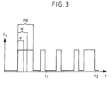
- a square-wave pulse voltage is present at the output terminal DF of the controller whose temporal course in Fig. 3rd is shown. 3, the pulse width is PB of the square-wave voltage pulses at the output terminal DF changes over time.
- Generator is the pulse width of the voltage on terminal DF is large because the excitation circuit is interrupted for longer and is therefore a high one at terminal DF Voltage level is present.
- the generator is full busy or even overloaded, so indicate the impulses the voltage at the connection terminal DF is narrow on, because the excitation circuit of the generator predominantly closed is. In the closed state it is Transistor in the output stage of the controller conducting what a drop in the voltage at the output terminal DF Ground potential results.
- the regulator output voltage of the regulator 10 at the output terminal DF serves as a control signal and is supplied to the voltage converter 2.
- the voltage converter 2 is a DC-DC converter with a control connection S, an input connection E and an output connection A, which is connected to the consumer 4.
- the DC-DC converter 2 is controlled so that the output voltage Ua at the output terminal A is equal to or greater than the input voltage Ue at the input terminal E when the pulse width of the control signal at the control terminal S is large, and that the output voltage Ua is less than the input voltage Ue is when the pulse width of the control signal falls below a lower limit value w.
- a DC-DC converter 2 that works as described above can be, for example, a counter and a Assemble DA converter, its analog output signal to control the output stage of the DC-DC converter 2 serves. Is the digital value that corresponds to the meter reading high, so there is at the output of the DA converter analog signal with a high voltage level, so that the Output voltage at the output stage of the DC-DC converter 2 is high. In the opposite case, that is in the case of Presence of a controller signal with a small pulse width, becomes the output voltage at the output stage of the DC-DC converter is reduced.
- the DC-DC converter shown there is essentially a transistor 20 which is a bipolar Transistor or a field effect transistor can be and a base resistor 22. This converter converts one constant DC voltage into a clocked DC voltage um if the transistor 20 by the square pulse signal of the controller 10 is controlled.
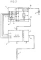
- Circuit elements in the circuit arrangement from Fig. 2 which are the same as the circuit elements from the circuit arrangement in Fig. 1, were with provided the same reference numerals.
- the circuit arrangement in Fig. 2 differs essentially from that 1 only in that as Voltage converter an AC-AC converter 5 with three input connections E1, E2 and E3 is provided and that the Current consumer 4 upstream of a rectifier circuit 6 is.
- At the inputs E1, E2 and E3 of the AC-AC converter 5 are in the stator windings 11, 12 and 13 induced alternating voltages.
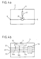
- the voltage converter can, as can be seen from Fig. 4b, a thyristor unit with multiple thyristors 50a, 50b and 50c included.
- the Thyristors serve as AC converters that are connected to the Inputs E1, E2 and E3 present alternating currents given voltage into one or more alternating currents convert from lower voltage.
- the AC-AC converter 5 includes a circuit 52 which is provided to the as Control signal used controller signal at the control input S of the Converter 5 in suitable for driving the thyristors Convert signals. It is also conceivable at the exit of the AC-AC converter an AC transformer 54 to provide.
- the output voltage Uw of the AC-AC converter like the output voltage of the DC-DC converter.
- the relationships that are related with the description of the circuit arrangement 1 have been described above.
- DC-DC converter and AC-AC converters also from other circuit components build up.
- the circuit structure proposed here DC-DC converter and the AC-AC converter represents only one possible design variant of a multitude of design variants represents.
- the pulse width PB is a measure of the utilization of the three-phase generator 1. Large pulse widths PB indicate a low utilization of the generator and small pulse widths PB indicate a high utilization or overload of the generator 1. If the pulse width of the rectangular pulse of the control voltage falls below a lower limit w, as is the case, for example, at a time t 1 , the output voltage of the voltage converter 2 or 5 is reduced in order to reduce the current consumption of the load 4 connected to the voltage converter. This in turn leads to the pulse width of the rectangular pulse of the control voltage increasing. As can be seen from FIG. 3, the pulse width PB is already significantly larger at a later time t 2 than at the earlier time t 1 .
- the pulse width is greater than an upper limit value W at time t 2. If the pulse width PB is greater than an upper limit value W, the output voltage of the voltage converter 2 or 5 is increased. Increasing and reducing the output voltage of the voltage transformers ensures that the current consumption of the consumer is limited and that the generator is not overloaded.
Landscapes
- Engineering & Computer Science (AREA)
- Power Engineering (AREA)
- Life Sciences & Earth Sciences (AREA)
- Sustainable Development (AREA)
- Sustainable Energy (AREA)
- Physics & Mathematics (AREA)
- Electromagnetism (AREA)
- General Physics & Mathematics (AREA)
- Radar, Positioning & Navigation (AREA)
- Automation & Control Theory (AREA)
- Control Of Eletrric Generators (AREA)
- Control Of Charge By Means Of Generators (AREA)
Description
- immer dann ein Herabsetzen der Ausgangsspannung des Spannungswandlers erfolgt, wenn die Impulsbreite des am Ausgangsanschluß des Reglers anliegenden Reglersignals einen unteren Grenzwert w unterschreitet und
- ein Erhöhen der Ausgangsspannung des Spannungswandlers immer dann erfolgt, wenn die Pulsbreite des an der Ausgangsanschluß des Reglers anliegenden Reglersignals eine obere Grenze W überschreitet.
- Fig. 1
- eine erste Ausführungsform der erfindungsgemäßen Schaltungsanordnung, bei der der Spannungwandler ein DC-DC-Wandler ist;
- Fig. 2
- eine zweite Ausführungsform der erfindungsgmäßen Schaltungsanordnung, bei der der Spannungswandler ein AC-AC-Wandler ist;
- Fig. 3
- den zeitlichen Spannungsverlauf des Steuersignals;
- Fig. 4a
- eine mögliche Ausführungsvariante des Spannungswandlers und
- Fig. 4b
- eine weitere mögliche Ausführungsvariante des Spannungwandlers.
Claims (9)
- Schaltungsanordnung zur Steuerung der Stromaufnahme eines oder mehrerer leistungsstarker Verbraucher (4) in einem Kraftfahrzeug, miteinem Drehstromgenerator (1),einem im Drehstromgenerator (1) untergebrachten Regler (10) zur Regelung der Generatorausgangsspannung mit einer Ausgangsklemme (DF),einer durch den Drehstromgenerator (1) aufladbaren Fahrzeugbatterie (3), undeinem steuerbaren Spannungswandler (2; 5), dera) wenigstens einen Eingangsanschluß (E; E1, E2, E3) zum Empfangen einer von dem Drehstromgenerator (1) gelieferten Eingangsspannung (Ue) aufweist,b) einen Steueranschluß (S) zum Empfangen eines an der Ausgangsklemme (DF) des Reglers (10) anliegenden Reglersignals (Us) besitzt, undc) wenigstens einen Ausgangsanschluß (A) zur Versorgung des leistungsstarken Verbrauchers (4) mit einer Ausgangsspannung (Ua) aufweist,d) wobei die Eingangsspannung (Ue) in Abhängigkeit von dem Reglersignal (Us) in eine Ausgangsspannung (Ua) umgewandelt wird.
- Schaltungsanordnung nach Anspruch 1, bei der das Reglersignal (Us) ein Rechtecksignal mit veränderlicher Impulsbreite (PB) ist.
- Schaltungsanordnung nach Anspruch 2, bei der der Spannungswandler ein DC-DC-Wandler mit einem Eingangsanschluß (E) und einem Ausgangsanschluß (A) ist, dessen Eingangsanschluß (E) zum Empfang der vom Drehstromgenerator (1) gelieferten Spannung (Ue) mit dessen Ausgangsanschluß (B+) verbunden ist und der eine von der Pulsbreite (PB) der Rechteckimpulse des Steuersignals (Us) abhängige Ausgangsspannung (Ua (PB)) liefert.
- Schaltungsanordnung nach Anspruch 2 oder 3, bei der der DC-DC-Wandler (2) im wesentlichen einen Zähler zur Erfassung der Impulsbreite (PB) bzw. der Impulsdauer und einen DA-Wandler enthält, dessen Ausgangsspannung proportional zu dem vom Zähler gelieferten digitalen Wert ist.
- Schaltungsanordnung nach Anspruch 2 oder 3, bei der der DC-DC-Wandler (2) die Gleichspannung am Eingang (E) mittels eines Transistors (20), an dessen Basis das Reglersignal (Us) anliegt, in eine getaktete Gleichspannung umwandelt und diese am Ausgangsanschluß (A) ausgibt.
- Schaltungsanordnung nach Anspruch 2, bei dem der Spannungswandler (5) ein AC-AC-Wandler ist, an dessen Eingängen (E1, E2 und E3) die in Ständerspulen (11, 12, 13) des Drehstromgenerators (1) induzierten Wechselspannungen anlegen und der eine von der Pulsbreite (PB) der Rechteckimpulse des Reglersignals (Us) abhängige Ausgangswechselspannung (Uw (PB)) liefert.
- Schaltungsanordnung nach Anspruch 5, bei der der AC-AC-Wandler (5) mehrere Thyristoren (50a, 50b und 50c) enthält, die über ihre Steueranschlüsse durch das Reglersignal gesteuert werden.
- Schaltungsanordnung nach Anspruch 6, bei der die Ausgangsanschlüsse des AC-AC-Wandlers (5) mit den Eingängen einer dem leistungsstarken Verbraucher (4) vorgeschalteten Gleichrichterschaltung (6) verbunden sind.
- Verfahren zur Steuerung der Stromaufnahme eines oder mehrerer leistungsstarker Verbraucher in einem Kraftfahrzeug, das mittels einer in Anspruch 1 angegebenen Schaltungsanordnung durchgeführt wird, in der an der Ausgangsklemme (DF) des Reglers (10) ein Reglersignal (Us) mit veränderlicher Pulsbreite (PB) anliegt, bei demein Herabsetzen der Ausgangsspannung (Ua) des Spannungswandlers (2, 5) erfolgt, wenn die Pulsbreite (PB) des an der Ausgangsklemme (DF) des Reglers (10) anliegenden Reglersignals (Us) einen unteren Grenzwert (w) unterschreitet undein Erhöhen der Ausgangsspannung (Ua) des Spannungswandlers (2; 5) erfolgt, wenn die Pulsbreite (PB) des Reglersignals (Us) eine obere Grenze (W) überschreitet.
Applications Claiming Priority (3)
| Application Number | Priority Date | Filing Date | Title |
|---|---|---|---|
| DE4445647A DE4445647A1 (de) | 1994-12-21 | 1994-12-21 | Steuerung der Stromaufnahme mehrerer Stromverbraucher in einem Kraftfahrzeug |
| DE4445647 | 1994-12-21 | ||
| PCT/EP1995/004615 WO1996019362A1 (de) | 1994-12-21 | 1995-11-23 | Steuerung der stromaufnahme mehrerer stromverbraucher in einem kraftfahrzeug |
Publications (2)
| Publication Number | Publication Date |
|---|---|
| EP0802867A1 EP0802867A1 (de) | 1997-10-29 |
| EP0802867B1 true EP0802867B1 (de) | 1998-09-16 |
Family
ID=6536493
Family Applications (1)
| Application Number | Title | Priority Date | Filing Date |
|---|---|---|---|
| EP95938464A Expired - Lifetime EP0802867B1 (de) | 1994-12-21 | 1995-11-23 | Steuerung der stromaufnahme mehrerer stromverbraucher in einem kraftfahrzeug |
Country Status (5)
| Country | Link |
|---|---|
| US (1) | US6900554B1 (de) |
| EP (1) | EP0802867B1 (de) |
| JP (1) | JP3681177B2 (de) |
| DE (2) | DE4445647A1 (de) |
| WO (1) | WO1996019362A1 (de) |
Families Citing this family (7)
| Publication number | Priority date | Publication date | Assignee | Title |
|---|---|---|---|---|
| DE19829150A1 (de) * | 1998-06-30 | 2000-01-13 | Bosch Gmbh Robert | Verfahren und Vorrichtung zur Energieverteilung in einem Kraftfahrzeug |
| DE19838504C1 (de) * | 1998-08-25 | 1999-07-08 | Webasto Thermosysteme Gmbh | Verfahren zum Bestimmen der maximalen Betriebszeit eines Fahrzeug-Standheizgeräts |
| DE19920842A1 (de) * | 1998-10-01 | 2000-04-13 | Volkswagen Ag | Verfahren zur Bestimmung der Leistungsreserve eines Generators |
| DE19953373B4 (de) * | 1999-11-06 | 2004-07-15 | Audi Ag | Vorrichtung zur Spannungsversorgung in einem Kraftfahrzeug |
| DE102004051530A1 (de) * | 2004-10-22 | 2006-05-04 | Audi Ag | Kraftfahrzeug mit einem Rekuperationsgenerator |
| DE102005060129A1 (de) * | 2005-12-16 | 2007-06-21 | Bayerische Motoren Werke Ag | Verfahren zum Steuern eines Bordnetzes für ein Kraftfahrzeug |
| DE102008035664B3 (de) * | 2008-07-31 | 2010-02-25 | Continental Automotive Gmbh | Schaltungssanordnung und System |
Family Cites Families (14)
| Publication number | Priority date | Publication date | Assignee | Title |
|---|---|---|---|---|
| DE3007941A1 (de) | 1980-03-01 | 1981-09-17 | Robert Bosch Gmbh, 7000 Stuttgart | Zweispannungs-netzanlage |
| US4459537A (en) * | 1982-11-22 | 1984-07-10 | General Motors Corporation | Up-down voltage regulator |
| DE3509073C2 (de) * | 1984-03-24 | 1995-04-20 | Volkswagen Ag | Elektrische Heizung, insbesondere für Kraftfahrzeuge |
| EP0265144B1 (de) * | 1986-10-16 | 1993-05-26 | Cadac Holdings Limited | Alternator und hierfür angewendeter Regler |
| CA2011563C (en) * | 1989-03-08 | 1994-05-10 | Kiyoshi Nakata | Power conversion system |
| DE3936638C1 (en) * | 1989-11-03 | 1991-03-14 | Mercedes-Benz Aktiengesellschaft, 7000 Stuttgart, De | Ensuring electrical power supply in motor vehicle - grouping electrical appliances according to their importance for safety of vehicle |
| US6218643B1 (en) * | 1991-07-18 | 2001-04-17 | Mitsubishi Denki Kabushiki Kaisha | Power supplying apparatus for automotive part |
| US5291388A (en) * | 1992-04-16 | 1994-03-01 | Westinghouse Electric Corp. | Reconfigurable inverter apparatus for battery-powered vehicle drive |
| DE4320509A1 (de) * | 1992-06-22 | 1993-12-23 | Philipp Scherer Gmbh & Co | Schaltungsanordnung mit einem vorzugsweise spannungsgeregelten Drehstromgenerator als Energiequelle für eine Stromversorgung mit einstellbarer effektiver Versorgungsspannung für Fahrzeuge, insbesondere Kraftfahrzeuge, ferner Transformator oder Transduktor sowie Anwendungen der Schaltungsanordnung bzw. des Transformators oder Transduktors und elektrische Einrichtung |
| CA2108343A1 (en) * | 1992-10-14 | 1994-04-15 | Roy D. Schultz | Electronic power regulator for an automotive alternator |
| US5606244A (en) * | 1993-08-05 | 1997-02-25 | Ofer Energies Ltd. | Mobile AC power source system |
| JP3345519B2 (ja) * | 1994-06-08 | 2002-11-18 | 富士通株式会社 | 電源装置 |
| JP3515619B2 (ja) * | 1994-11-30 | 2004-04-05 | 株式会社日立製作所 | 電気車の駆動装置及び駆動制御方法 |
| JP3412330B2 (ja) * | 1995-04-24 | 2003-06-03 | 株式会社デンソー | 車両用発電装置 |
-
1994
- 1994-12-21 DE DE4445647A patent/DE4445647A1/de not_active Withdrawn
-
1995
- 1995-11-23 WO PCT/EP1995/004615 patent/WO1996019362A1/de not_active Ceased
- 1995-11-23 DE DE59503646T patent/DE59503646D1/de not_active Expired - Lifetime
- 1995-11-23 EP EP95938464A patent/EP0802867B1/de not_active Expired - Lifetime
- 1995-11-23 US US08/849,873 patent/US6900554B1/en not_active Expired - Fee Related
- 1995-11-23 JP JP51945296A patent/JP3681177B2/ja not_active Expired - Fee Related
Also Published As
| Publication number | Publication date |
|---|---|
| DE4445647A1 (de) | 1996-06-27 |
| JP3681177B2 (ja) | 2005-08-10 |
| JPH10511056A (ja) | 1998-10-27 |
| US6900554B1 (en) | 2005-05-31 |
| DE59503646D1 (de) | 1998-10-22 |
| EP0802867A1 (de) | 1997-10-29 |
| WO1996019362A1 (de) | 1996-06-27 |
Similar Documents
| Publication | Publication Date | Title |
|---|---|---|
| EP1784910B1 (de) | Spannungsregler mit überspannungsschutz | |
| DE3780320T2 (de) | Fahrzeug-leistungsversorgung mit mehrfachen leistungsversorgungsspannungen. | |
| DE69216365T2 (de) | Stromversorgungsvorrichtung für ein Fahrzeug | |
| DE3844607C3 (de) | Stromversorgungsschaltung für ein Kraftfahrzeug mit zwei unterschiedlichen Verbraucherspannungen | |
| DE4306489B4 (de) | Verfahren und Gerät zum Steuern des Ladens einer Batterie | |
| DE60215902T2 (de) | Antriebsgerät, Steuerverfahren und Programmspeichermedium für das Antriebsgerät, und Apparatur zur Erzeugung von Energie | |
| DE10118177B4 (de) | Energieversorgungsvorrichtung für Fahrzeuge | |
| EP1920525B1 (de) | Steuerungsanordnung für einen spannungskonverter und verfahren | |
| EP0872014B1 (de) | Fahrzeugbordnetz | |
| DE102019201606A1 (de) | Verfahren zum elektrischen Vorladen eines Zwischenkreiskondensators im Hochvoltsystem eines zumindest teilweise elektrisch angetriebenen Kraftfahrzeugs sowie ein derartiges Hochvoltsystem | |
| EP0802867B1 (de) | Steuerung der stromaufnahme mehrerer stromverbraucher in einem kraftfahrzeug | |
| EP0772904B1 (de) | Vorrichtung zur spannungsversorgung mit zwei ausgangsspannungen | |
| DE2814424A1 (de) | Schaltungsanordnung zur glaettung der von einem elektrischen generator abgegebenen spannung | |
| DE68925409T2 (de) | Anordnung zur Steuerung eines elektrischen Ladungssystems | |
| WO1999063649A1 (de) | Spannungsumschaltvorrichtung | |
| DE69524139T2 (de) | Selektives Stromversorgungsgerät für elektrische Verbraucher und Zündsystem von inneren Brennkraftmaschinen in Motorfahrzeugen | |
| DE60002711T2 (de) | Bürstenloser Motor, Verfahren und Schaltung zu seiner Regelung | |
| DE19614816C1 (de) | Elektronisches Schaltnetzteil und dessen Verwendung | |
| EP1142080A1 (de) | Verfahren und einrichtung zur spannungsversorgung | |
| EP0472805B1 (de) | Einrichtung zur Begrenzung der Klemmenspannung bei einer Drehstromlichtmaschine | |
| DE3432127A1 (de) | Gleichstromgenerator | |
| EP0327881A1 (de) | Schaltnetzteil | |
| DE102018124668A1 (de) | Verfahren zum Regeln des Ladens und Entladens eines Batteriesystems und Vorrichtung | |
| WO2008142152A2 (de) | Vorrichtung zur spannungsversorgung des bordnetzes eines kraftfahrzeugs | |
| EP0811529A2 (de) | Schaltungsanordnung mit verringerter EMV-Abstrahlung |
Legal Events
| Date | Code | Title | Description |
|---|---|---|---|
| PUAI | Public reference made under article 153(3) epc to a published international application that has entered the european phase |
Free format text: ORIGINAL CODE: 0009012 |
|
| 17P | Request for examination filed |
Effective date: 19970212 |
|
| AK | Designated contracting states |
Kind code of ref document: A1 Designated state(s): BE DE FR GB |
|
| GRAG | Despatch of communication of intention to grant |
Free format text: ORIGINAL CODE: EPIDOS AGRA |
|
| GRAG | Despatch of communication of intention to grant |
Free format text: ORIGINAL CODE: EPIDOS AGRA |
|
| GRAH | Despatch of communication of intention to grant a patent |
Free format text: ORIGINAL CODE: EPIDOS IGRA |
|
| 17Q | First examination report despatched |
Effective date: 19980213 |
|
| GRAH | Despatch of communication of intention to grant a patent |
Free format text: ORIGINAL CODE: EPIDOS IGRA |
|
| GRAA | (expected) grant |
Free format text: ORIGINAL CODE: 0009210 |
|
| AK | Designated contracting states |
Kind code of ref document: B1 Designated state(s): BE DE FR GB |
|
| REF | Corresponds to: |
Ref document number: 59503646 Country of ref document: DE Date of ref document: 19981022 |
|
| GBT | Gb: translation of ep patent filed (gb section 77(6)(a)/1977) |
Effective date: 19981116 |
|
| ET | Fr: translation filed | ||
| PLBE | No opposition filed within time limit |
Free format text: ORIGINAL CODE: 0009261 |
|
| STAA | Information on the status of an ep patent application or granted ep patent |
Free format text: STATUS: NO OPPOSITION FILED WITHIN TIME LIMIT |
|
| 26N | No opposition filed | ||
| REG | Reference to a national code |
Ref country code: GB Ref legal event code: IF02 |
|
| PGFP | Annual fee paid to national office [announced via postgrant information from national office to epo] |
Ref country code: DE Payment date: 20121130 Year of fee payment: 18 |
|
| PGFP | Annual fee paid to national office [announced via postgrant information from national office to epo] |
Ref country code: GB Payment date: 20121126 Year of fee payment: 18 Ref country code: BE Payment date: 20121129 Year of fee payment: 18 |
|
| PGFP | Annual fee paid to national office [announced via postgrant information from national office to epo] |
Ref country code: FR Payment date: 20121214 Year of fee payment: 18 |
|
| BERE | Be: lapsed |
Owner name: *AUDI A.G. Effective date: 20131130 |
|
| GBPC | Gb: european patent ceased through non-payment of renewal fee |
Effective date: 20131123 |
|
| REG | Reference to a national code |
Ref country code: FR Ref legal event code: ST Effective date: 20140731 |
|
| PG25 | Lapsed in a contracting state [announced via postgrant information from national office to epo] |
Ref country code: DE Free format text: LAPSE BECAUSE OF NON-PAYMENT OF DUE FEES Effective date: 20140603 |
|
| REG | Reference to a national code |
Ref country code: DE Ref legal event code: R119 Ref document number: 59503646 Country of ref document: DE Effective date: 20140603 |
|
| PG25 | Lapsed in a contracting state [announced via postgrant information from national office to epo] |
Ref country code: BE Free format text: LAPSE BECAUSE OF NON-PAYMENT OF DUE FEES Effective date: 20131130 |
|
| PG25 | Lapsed in a contracting state [announced via postgrant information from national office to epo] |
Ref country code: FR Free format text: LAPSE BECAUSE OF NON-PAYMENT OF DUE FEES Effective date: 20131202 Ref country code: GB Free format text: LAPSE BECAUSE OF NON-PAYMENT OF DUE FEES Effective date: 20131123 |