EP0802852B1 - Verfahren und vorrichtung zum giessen kontaktlinsen und deren verpackung - Google Patents
Verfahren und vorrichtung zum giessen kontaktlinsen und deren verpackung Download PDFInfo
- Publication number
- EP0802852B1 EP0802852B1 EP96905224A EP96905224A EP0802852B1 EP 0802852 B1 EP0802852 B1 EP 0802852B1 EP 96905224 A EP96905224 A EP 96905224A EP 96905224 A EP96905224 A EP 96905224A EP 0802852 B1 EP0802852 B1 EP 0802852B1
- Authority
- EP
- European Patent Office
- Prior art keywords
- webs
- mold cavities
- posterior
- anterior
- web
- Prior art date
- Legal status (The legal status is an assumption and is not a legal conclusion. Google has not performed a legal analysis and makes no representation as to the accuracy of the status listed.)
- Expired - Lifetime
Links
- 238000000034 method Methods 0.000 title claims abstract description 39
- 238000000465 moulding Methods 0.000 title claims abstract description 19
- 239000000463 material Substances 0.000 claims abstract description 62
- 230000013011 mating Effects 0.000 claims abstract description 18
- 230000007246 mechanism Effects 0.000 claims description 7
- 238000007666 vacuum forming Methods 0.000 claims description 6
- 239000012530 fluid Substances 0.000 claims description 2
- 239000000376 reactant Substances 0.000 claims 3
- 238000000151 deposition Methods 0.000 claims 2
- 230000005855 radiation Effects 0.000 claims 2
- 230000000887 hydrating effect Effects 0.000 claims 1
- 238000012856 packing Methods 0.000 claims 1
- 239000000178 monomer Substances 0.000 abstract description 12
- 238000004806 packaging method and process Methods 0.000 abstract description 6
- 239000007788 liquid Substances 0.000 abstract description 5
- 238000004519 manufacturing process Methods 0.000 description 6
- 238000006116 polymerization reaction Methods 0.000 description 4
- 229920001577 copolymer Polymers 0.000 description 3
- 230000015572 biosynthetic process Effects 0.000 description 2
- 230000036571 hydration Effects 0.000 description 2
- 238000006703 hydration reaction Methods 0.000 description 2
- 238000001746 injection moulding Methods 0.000 description 2
- 238000007689 inspection Methods 0.000 description 2
- 239000004033 plastic Substances 0.000 description 2
- 229920003023 plastic Polymers 0.000 description 2
- -1 polyarylsulfone Polymers 0.000 description 2
- 229920002635 polyurethane Polymers 0.000 description 2
- 239000004814 polyurethane Substances 0.000 description 2
- 239000004800 polyvinyl chloride Substances 0.000 description 2
- 229920000915 polyvinyl chloride Polymers 0.000 description 2
- 230000001360 synchronised effect Effects 0.000 description 2
- 229910000760 Hardened steel Inorganic materials 0.000 description 1
- 239000004697 Polyetherimide Substances 0.000 description 1
- 239000004743 Polypropylene Substances 0.000 description 1
- 239000004793 Polystyrene Substances 0.000 description 1
- FAPWRFPIFSIZLT-UHFFFAOYSA-M Sodium chloride Chemical compound [Na+].[Cl-] FAPWRFPIFSIZLT-UHFFFAOYSA-M 0.000 description 1
- 239000002131 composite material Substances 0.000 description 1
- 238000007334 copolymerization reaction Methods 0.000 description 1
- 238000005520 cutting process Methods 0.000 description 1
- 229920001971 elastomer Polymers 0.000 description 1
- 239000011888 foil Substances 0.000 description 1
- 239000000017 hydrogel Substances 0.000 description 1
- 229920000554 ionomer Polymers 0.000 description 1
- 239000000203 mixture Substances 0.000 description 1
- 238000012858 packaging process Methods 0.000 description 1
- 229920003229 poly(methyl methacrylate) Polymers 0.000 description 1
- 229920000728 polyester Polymers 0.000 description 1
- 229920001601 polyetherimide Polymers 0.000 description 1
- 239000004926 polymethyl methacrylate Substances 0.000 description 1
- 229920001155 polypropylene Polymers 0.000 description 1
- 229920002223 polystyrene Polymers 0.000 description 1
- 238000003825 pressing Methods 0.000 description 1
- 229910052710 silicon Inorganic materials 0.000 description 1
- 239000010703 silicon Substances 0.000 description 1
- 229920002379 silicone rubber Polymers 0.000 description 1
- 239000011780 sodium chloride Substances 0.000 description 1
- 239000007787 solid Substances 0.000 description 1
Images


Classifications
-
- B—PERFORMING OPERATIONS; TRANSPORTING
- B29—WORKING OF PLASTICS; WORKING OF SUBSTANCES IN A PLASTIC STATE IN GENERAL
- B29D—PRODUCING PARTICULAR ARTICLES FROM PLASTICS OR FROM SUBSTANCES IN A PLASTIC STATE
- B29D11/00—Producing optical elements, e.g. lenses or prisms
- B29D11/00009—Production of simple or compound lenses
- B29D11/00038—Production of contact lenses
- B29D11/00125—Auxiliary operations, e.g. removing oxygen from the mould, conveying moulds from a storage to the production line in an inert atmosphere
- B29D11/00192—Demoulding, e.g. separating lenses from mould halves
-
- B—PERFORMING OPERATIONS; TRANSPORTING
- B29—WORKING OF PLASTICS; WORKING OF SUBSTANCES IN A PLASTIC STATE IN GENERAL
- B29C—SHAPING OR JOINING OF PLASTICS; SHAPING OF MATERIAL IN A PLASTIC STATE, NOT OTHERWISE PROVIDED FOR; AFTER-TREATMENT OF THE SHAPED PRODUCTS, e.g. REPAIRING
- B29C33/00—Moulds or cores; Details thereof or accessories therefor
- B29C33/34—Moulds or cores; Details thereof or accessories therefor movable, e.g. to or from the moulding station
- B29C33/36—Moulds or cores; Details thereof or accessories therefor movable, e.g. to or from the moulding station continuously movable in one direction, e.g. in a closed circuit
-
- B—PERFORMING OPERATIONS; TRANSPORTING
- B29—WORKING OF PLASTICS; WORKING OF SUBSTANCES IN A PLASTIC STATE IN GENERAL
- B29C—SHAPING OR JOINING OF PLASTICS; SHAPING OF MATERIAL IN A PLASTIC STATE, NOT OTHERWISE PROVIDED FOR; AFTER-TREATMENT OF THE SHAPED PRODUCTS, e.g. REPAIRING
- B29C39/00—Shaping by casting, i.e. introducing the moulding material into a mould or between confining surfaces without significant moulding pressure; Apparatus therefor
- B29C39/02—Shaping by casting, i.e. introducing the moulding material into a mould or between confining surfaces without significant moulding pressure; Apparatus therefor for making articles of definite length, i.e. discrete articles
- B29C39/04—Shaping by casting, i.e. introducing the moulding material into a mould or between confining surfaces without significant moulding pressure; Apparatus therefor for making articles of definite length, i.e. discrete articles using movable moulds not applied
- B29C39/06—Shaping by casting, i.e. introducing the moulding material into a mould or between confining surfaces without significant moulding pressure; Apparatus therefor for making articles of definite length, i.e. discrete articles using movable moulds not applied continuously movable, e.g. along a production line
-
- B—PERFORMING OPERATIONS; TRANSPORTING
- B29—WORKING OF PLASTICS; WORKING OF SUBSTANCES IN A PLASTIC STATE IN GENERAL
- B29C—SHAPING OR JOINING OF PLASTICS; SHAPING OF MATERIAL IN A PLASTIC STATE, NOT OTHERWISE PROVIDED FOR; AFTER-TREATMENT OF THE SHAPED PRODUCTS, e.g. REPAIRING
- B29C69/00—Combinations of shaping techniques not provided for in a single one of main groups B29C39/00 - B29C67/00, e.g. associations of moulding and joining techniques; Apparatus therefore
- B29C69/02—Combinations of shaping techniques not provided for in a single one of main groups B29C39/00 - B29C67/00, e.g. associations of moulding and joining techniques; Apparatus therefore of moulding techniques only
-
- B—PERFORMING OPERATIONS; TRANSPORTING
- B29—WORKING OF PLASTICS; WORKING OF SUBSTANCES IN A PLASTIC STATE IN GENERAL
- B29D—PRODUCING PARTICULAR ARTICLES FROM PLASTICS OR FROM SUBSTANCES IN A PLASTIC STATE
- B29D11/00—Producing optical elements, e.g. lenses or prisms
- B29D11/00009—Production of simple or compound lenses
- B29D11/00038—Production of contact lenses
- B29D11/00125—Auxiliary operations, e.g. removing oxygen from the mould, conveying moulds from a storage to the production line in an inert atmosphere
- B29D11/0023—Transferring contact lenses
-
- B—PERFORMING OPERATIONS; TRANSPORTING
- B29—WORKING OF PLASTICS; WORKING OF SUBSTANCES IN A PLASTIC STATE IN GENERAL
- B29D—PRODUCING PARTICULAR ARTICLES FROM PLASTICS OR FROM SUBSTANCES IN A PLASTIC STATE
- B29D11/00—Producing optical elements, e.g. lenses or prisms
- B29D11/00009—Production of simple or compound lenses
- B29D11/00038—Production of contact lenses
- B29D11/00259—Plants for the production of contact lenses
-
- B—PERFORMING OPERATIONS; TRANSPORTING
- B29—WORKING OF PLASTICS; WORKING OF SUBSTANCES IN A PLASTIC STATE IN GENERAL
- B29D—PRODUCING PARTICULAR ARTICLES FROM PLASTICS OR FROM SUBSTANCES IN A PLASTIC STATE
- B29D11/00—Producing optical elements, e.g. lenses or prisms
- B29D11/00009—Production of simple or compound lenses
- B29D11/0048—Moulds for lenses
- B29D11/00567—Moulds for lenses wherein the mould forms part of the final package for lenses
-
- B—PERFORMING OPERATIONS; TRANSPORTING
- B29—WORKING OF PLASTICS; WORKING OF SUBSTANCES IN A PLASTIC STATE IN GENERAL
- B29D—PRODUCING PARTICULAR ARTICLES FROM PLASTICS OR FROM SUBSTANCES IN A PLASTIC STATE
- B29D22/00—Producing hollow articles
- B29D22/003—Containers for packaging, storing or transporting, e.g. bottles, jars, cans, barrels, tanks
-
- B—PERFORMING OPERATIONS; TRANSPORTING
- B65—CONVEYING; PACKING; STORING; HANDLING THIN OR FILAMENTARY MATERIAL
- B65B—MACHINES, APPARATUS OR DEVICES FOR, OR METHODS OF, PACKAGING ARTICLES OR MATERIALS; UNPACKING
- B65B25/00—Packaging other articles presenting special problems
- B65B25/008—Packaging other articles presenting special problems packaging of contact lenses
-
- B—PERFORMING OPERATIONS; TRANSPORTING
- B65—CONVEYING; PACKING; STORING; HANDLING THIN OR FILAMENTARY MATERIAL
- B65B—MACHINES, APPARATUS OR DEVICES FOR, OR METHODS OF, PACKAGING ARTICLES OR MATERIALS; UNPACKING
- B65B9/00—Enclosing successive articles, or quantities of material, e.g. liquids or semiliquids, in flat, folded, or tubular webs of flexible sheet material; Subdividing filled flexible tubes to form packages
- B65B9/02—Enclosing successive articles, or quantities of material between opposed webs
- B65B9/04—Enclosing successive articles, or quantities of material between opposed webs one or both webs being formed with pockets for the reception of the articles, or of the quantities of material
- B65B9/045—Enclosing successive articles, or quantities of material between opposed webs one or both webs being formed with pockets for the reception of the articles, or of the quantities of material for single articles, e.g. tablets
-
- B—PERFORMING OPERATIONS; TRANSPORTING
- B29—WORKING OF PLASTICS; WORKING OF SUBSTANCES IN A PLASTIC STATE IN GENERAL
- B29C—SHAPING OR JOINING OF PLASTICS; SHAPING OF MATERIAL IN A PLASTIC STATE, NOT OTHERWISE PROVIDED FOR; AFTER-TREATMENT OF THE SHAPED PRODUCTS, e.g. REPAIRING
- B29C2791/00—Shaping characteristics in general
- B29C2791/004—Shaping under special conditions
- B29C2791/006—Using vacuum
-
- B—PERFORMING OPERATIONS; TRANSPORTING
- B29—WORKING OF PLASTICS; WORKING OF SUBSTANCES IN A PLASTIC STATE IN GENERAL
- B29C—SHAPING OR JOINING OF PLASTICS; SHAPING OF MATERIAL IN A PLASTIC STATE, NOT OTHERWISE PROVIDED FOR; AFTER-TREATMENT OF THE SHAPED PRODUCTS, e.g. REPAIRING
- B29C51/00—Shaping by thermoforming, i.e. shaping sheets or sheet like preforms after heating, e.g. shaping sheets in matched moulds or by deep-drawing; Apparatus therefor
- B29C51/08—Deep drawing or matched-mould forming, i.e. using mechanical means only
- B29C51/082—Deep drawing or matched-mould forming, i.e. using mechanical means only by shaping between complementary mould parts
-
- B—PERFORMING OPERATIONS; TRANSPORTING
- B29—WORKING OF PLASTICS; WORKING OF SUBSTANCES IN A PLASTIC STATE IN GENERAL
- B29C—SHAPING OR JOINING OF PLASTICS; SHAPING OF MATERIAL IN A PLASTIC STATE, NOT OTHERWISE PROVIDED FOR; AFTER-TREATMENT OF THE SHAPED PRODUCTS, e.g. REPAIRING
- B29C51/00—Shaping by thermoforming, i.e. shaping sheets or sheet like preforms after heating, e.g. shaping sheets in matched moulds or by deep-drawing; Apparatus therefor
- B29C51/10—Forming by pressure difference, e.g. vacuum
-
- Y—GENERAL TAGGING OF NEW TECHNOLOGICAL DEVELOPMENTS; GENERAL TAGGING OF CROSS-SECTIONAL TECHNOLOGIES SPANNING OVER SEVERAL SECTIONS OF THE IPC; TECHNICAL SUBJECTS COVERED BY FORMER USPC CROSS-REFERENCE ART COLLECTIONS [XRACs] AND DIGESTS
- Y10—TECHNICAL SUBJECTS COVERED BY FORMER USPC
- Y10S—TECHNICAL SUBJECTS COVERED BY FORMER USPC CROSS-REFERENCE ART COLLECTIONS [XRACs] AND DIGESTS
- Y10S425/00—Plastic article or earthenware shaping or treating: apparatus
- Y10S425/808—Lens mold
Definitions
- the present invention pertains to a method and apparatus for molding lenses, and particularly to a method and apparatus for molding lenses such as contact lenses which have a finished edge and which are suitable for wearing directly on the eye.
- the invention more particularly pertains to a novel method and apparatus for molding contact lenses and making their containers which utilizes continuous web feeding methods wherein the lenses are molded between posterior and anterior mold cavities formed in first and second webs of material, respectively. The webs are brought together in aligned fashion by synchronized feeding mechanisms for curing of a liquid lens material previously disposed within one of the cavities, and thereafter separated from one another to expose the molded lenses.
- packaging containers for the molded lenses are formed in the same web of material in which the lenses are molded
- Cast molding of contact lenses has proven a reliable and economical method of high volume lens production.
- manufacturing methods of molded lenses have seen increased emphasis on mold techniques which consistently produce non-reject lenses on a large production scale. Attention is directed to U.S. Patent No. 5,271,875 which issued on Dec. 21, 1993 and is of common ownership with the present application, the '875 patent being incorporated herein by reference.
- the '875 patent relates to a method of molding a contact lens using anterior and posterior mold halves which are used only once by being brought together to mold the lens therebetween, separated following curing of the lens material, and then discarded.
- the mold halves include tapered side walls to form cooperating alignment means between the mold halves as they are brought together and clamped (see Figs. 2-17 therein) or taper-locked (see Figs. 21-24 therein) to provide the needed force to squeeze the mold halves together during polymerization.
- deformable rim and annulus features 52 and 47 encircling the surface cavities of the anterior and posterior mold halves, respectively, are provided for engaging and deforming against one another during curing of the monomer contained in the mold by virtue of a clamping force applied to the mold halves.
- the juncture of the rim and annulus features forms the finished edge of the lens in addition to accommodating shrinkage of the lens material during curing thereof by slowly bringing the respective mold surface cavities toward one another as the rim and annulus features forcibly deform against one another.
- GB-A-2 040 213 also discloses a method and apparatus for making lenses. This disclosure teaches the provision of a strip having recessed mould cavities into which a plastics material is provided. A cover including depressions which fit snugly into the recesses is provided, and the plastics material cast to form the lens.
- the present invention addresses the desire to reduce manufacturing costs of molded lenses by providing an improved automated method for molding lenses between posterior and anterior mold cavities formed in longitudinally spaced relation on first and second, aligned webs of material which are continuously fed through the lens molding process.
- the lens molding process generally comprises the steps of: (1) forming the anterior and posterior mold cavities in the first and second webs, respectively; (2) dispensing a liquid, curable, contact lens material in the anterior mold surface; (3) bringing the two webs together with the posterior and anterior mold cavities in sequential mating alignment; (4) curing the liquid lens material to a solid state while accommodating for monomer shrinkage; and (5) separating the webs following the curing stage to retrieve the finished lenses.
- Ancillary process steps include lens inspection, hydration and packaging.
- the lens packages are formed from the same webs of material used in the molding process.
- the curable lens materials generally are composed of a curable mixture of polymerizable monomers. Curing results in copolymerization of the monomers to form a copolymeric shaped article.
- the curable lens materials include those known in the art for preparing hard or soft contact lenses. As known in the art, hard lenses include polymethylmethacrylate lenses and rigid gas permeable (RGP) lenses formed of a silicon or a fluorosilicon copolymer, and soft contact lenses include hydrophilic hydrogel lenses or silicone elastomer contact lenses.
- the webs of material may be made from a variety of materials which are capable of having a plurality of spaced mold cavities formed therein.
- the mold cavities may be formed in each web by a primary vacuum-forming operation followed by a secondary coining operation. Alternatively, the mold cavities may be formed concurrently with the webs in a continuous-line injection molding process.
- Acceptable materials for either or both of the webs are the same as those listed in the '875 patent and include polyurethane, rigid polyvinyl chloride, ionomer, polyarylsulfone, polyetherimide, polyester, polystyrene, rubber modified copolymer or rigid polyurethane, all of which are amenable to either of the above web/mold-making processes.
- the mold cavity profiles formed in the webs may be substantially identical to that shown and described in the '875 patent, or may have other profiles depending on the lens geometry desired. Also, various web feeding and mold centering means are described in detail below, although any method may be employed which feeds the anterior and posterior webs through the molding process in a fashion which aligns and centers the mold cavities in each web in mating engagement. This is accomplished with the individual mold halves of the '875 patent through the provision of telescoping side walls on the respective mold halves.
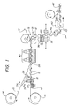
- Figure 1 a simplified schematic representation of one preferred lens manufacturing and packaging process according to the present invention.
- the process is carried out by providing first and second webs of material 10 and 12, respectively, which may advantageously be manufactured in rolls 14 and 16 from which webs 10 and 12 are simultaneously dispensed, respectively.
- Each web 10 and 12 is then individually subjected to a vacuum forming operation, such as at 15 on web 12, for forming the posterior and anterior mold cavities 18 and 20 therein, respectively.
- a secondary coining operation using hardened steel tools, such as at 22 on web 12 may additionally be performed on vacuum-formed cavities 18 and 20 to achieve the desired surface profiles.
- these cavity profiles may be substantially identical to those profiles shown and described in the '875 patent, and which are reproduced in Figs. 3A and 3B hereof.
- rim and annulus features 52 and 47 may be formed in anterior and posterior mold cavities 20 and 18, respectively, which relatively deform against one another to form a finished lens edge while also accommodating for monomer shrinkage during the polymerization stage (described below).
- tapered side walls 24 and 44 may be optionally provided, as seen in Fig. 3B, depending on whether or not other mold centering means are provided, examples of which will be described later. If other mold centering means are provided, then the tapered side walls 24 and 44 would not be necessary.
- mold cavities 18 and 20 in webs 10 and 12 may be implemented.
- cavities 18 and 20 may be formed simultaneously with webs 10 and 12 using a continuous-line injection molding process.
- possible materials from which webs 10 and 12 may be made include those listed in the '875 patent as described above.
- a metered amount of liquid monomer 21 is dispensed, as at station 26, into each of the anterior mold cavities 20 formed in web 12.
- the posterior and anterior webs 10 and 12, respectively, are then brought together, as at 28, for molding and curing a lens between the mating mold cavities, as at 30.
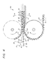
- each web 10 and 12 may be carried by a conveyor belt 27 and 29, respectively (Fig. 4), which belts each comprise a plurality of pivotally linked, web support blocks 31 and 33, respectively, with blocks 33 having concave recesses 49 to support cavities 20, and blocks 31 having apertures 45 to pass UV light therethrough to cure the monomer 21.
- the travel of belts 27 and 29 are synchronized to carry webs 10 and 12 with mold cavities 18 and 20 in said centered, mating engagement.
- conveyor belts 27 and 29 may function to both feed and align webs 10 and 12
- additional web feed/alignment means may be provided such as, for example, a track-feeding mechanism having rotating sprockets (not shown) which engage longitudinally spaced apertures 23 and 25 formed along the opposite side edges of each web 10 and 12, respectively (Fig. 2).
- each web 10 and 12 may be provided with the telescoping side walls 24 and 44, respectively, of Fig. 3B, which also serve as the centering means in the '875 patent as described above.
- FIG. 5 which shows a load-applying roller assembly 35 which includes a pair of laterally spaced rollers 37 and 37' positioned to rotate in traversing relationship over and adjacent the opposite side edges 31' of belt 27 as belt 27 travels past assembly 35.
- Rollers 37 and 37' carry a load 39 which applies a downward force F of predetermined magnitude against the conveyor belt 27 adjacent the opposite side edges 31' thereof.
- a support platen 41 is also provided over which belt 29 travels with platen 41 acting to apply a reactive force FR to belt 29, with assembly 35 and platen 41 acting together so as to apply the needed clamping force to squeeze the mold cavities 18 and 20 together during the curing stage 30 of the monomer 21.
- a clamping force of 20-40 pounds is preferred.
- curing is effected by a pair of UV lamps 43 which direct UV light through the longitudinally spaced apertures 45 formed in the support blocks 31 of belt 27, although other curing means (e.g., heat) may be used instead of or in addition to UV light.
- webs 10 and 12 may include any number of laterally spaced rows of mold cavities 18 and 20, respectively, with support blocks 31 and 33 including a respective number of laterally spaced apertures 45 and concave recesses 49 to accommodate mold cavities 18 and 20, respectively.
- webs 10 and 12 are separated, as at 32, whereupon the cast lenses 34 are removed from their respective mold cavities by appropriate means.
- the cast lenses 34 may be further processed by way of final curing and inspection.
- web 12 (and/or web 10) is subjected to second vacuum-forming and coining operations, as at 36 and 38, respectively, wherein a plurality of lens receptacles 40 are formed for deposit of the cast lenses 34 therein.
- the lens receptacles 40 are larger than the mold cavities 18 and 20 to accommodate for lens expansion during hydration, as at station 42, which follows the coining operation at 38.
- lens preserving fluid e.g., saline
- covering material e.g., foil
- FIG. 6 and 7 An alternate package forming scheme is shown in Figs. 6 and 7 wherein receptacles 40 are formed in laterally spaced relation to mold cavities 20 in web 12.
- a longitudinally extending perforating strip 50 may be formed between receptacles 40 and cavities 20 which may be subsequently torn or cut, as at 54 (or by other appropriate means), to form a separate receptacle strip 12'.
Landscapes
- Engineering & Computer Science (AREA)
- Mechanical Engineering (AREA)
- Health & Medical Sciences (AREA)
- Manufacturing & Machinery (AREA)
- Ophthalmology & Optometry (AREA)
- Casting Or Compression Moulding Of Plastics Or The Like (AREA)
- Eyeglasses (AREA)
- Moulds For Moulding Plastics Or The Like (AREA)
Claims (23)
- Verfahren zum Formen einer Vielzahl konkav-konvexer Linsen (34), das die folgenden Schritte umfasst:(a) Ausbilden hinterer und vorderer Linsen-Formhohlräume (18, 20) in Längsrichtung voneinander beabstandet in einer ersten bzw. einer zweiten Materialbahn (10, 12);(b) Einfüllen einer dosierten Menge an aushärtbarem Linsenmaterial (21) in jeden der hinteren Formhohlräume (20);(c) Ausrichten und gemeinsames Bewegen der ersten und der zweiten Materialbahn (10, 12);(d) Aushärten des Linsenmaterials (21); und(e) Trennen der ersten und der zweiten Bahn (10, 12), um jede Linse (34) freizugeben, die zwischen aufeinandergepassten hinteren und vorderen Linsen-Formhohlräumen (18, 20) gegossen wurde, dadurch gekennzeichnet, dass in Schritt (c) die aufeinander ausgerichteten hinteren und vorderen Formhohlräume (18, 20) nacheinander in zentrierten Passkontakt miteinander bewegt werden, und dass in Schritt (d) beim Aushärten eine Klemmkraft auf die ausgebildeten aufeinanderpassenden Bahnen (10, 12) ausgeübt wird, und durch die folgenden zusätzlichen Schritte:(f) Ausbilden einer Vielzahl von Packungsbehältern (40) in wenigstens der ersten oder der zweiten Materialbahn (10, 12), in die die gegossene Linse (34) zum Transport eingelegt wird; und(g) Anbringen einer dichten Abdeckung (40') über jedem der Behälter (40).
- Verfahren nach Anspruch 1, wobei in Schritt (f) die Verpackungsbehälter (40) über wenigstens den hinteren oder den vorderen Formhohlräumen (18, 20) der ersten bzw. der zweiten Bahn (10, 12) ausgebildet werden und sie ersetzen.
- Verfahren nach Anspruch 1, das des weiteren den Schritt des Abgebens eines Linsenwässerungsfluids in den Behälter (40) vor dem Anbringen der dichten Abdeckung (40') daran umfasst.
- Verfahren nach Anspruch 1, wobei ein Vakuumformmechanismus in Schritt (a) eingesetzt wird.
- Verfahren nach Anspruch 4, wobei ein Prägemechanismus nach dem Vakuumformmechanismus eingesetzt wird.
- Verfahren nach Anspruch 1, wobei die Bahnen (10, 12) und die Linsenformhohlräume (18, 20) gleichzeitig mit einem Spritzgießverfahren hergestellt werden.
- Verfahren nach Anspruch 1, wobei die Behälter (40) unter Verwendung eines Vakuumformmechanismus hergestellt werden.
- Verfahren zum Formen einer Vielzahl konkav-konvexer Linsen (34), das die folgenden Schritte umfasst:(a) Bereitstellen einer ersten und einer zweiten Materialbahn (10, 12);(b) Ausbilden aufeinander ausrichtbarer hinterer und vorderer Linsen-Formhohlräume (18, 20) in Längsrichtung voneinander beabstandet in der ersten bzw. der zweiten Materialbahn (10, 12);(c) Einfüllen einer dosierten Menge an aushärtbarem Linsenmaterial (21) in jeden der vorderen Formhohlräume (20);(d) Ausrichten und gemeinsames Bewegen der ersten und der zweiten Materialbahn (10, 12);(e) Aushärten des Linsenmaterials (21); und(f) Trennen der ersten und der zweiten Bahn (10, 12), um jede Linse (34) freizugeben, die zwischen aufeinandergepassten hinteren und vorderen Linsen-Formhohlräumen (18, 20) gegossen wurde, dadurch gekennzeichnet, dass die aufeinander ausgerichteten hinteren und vorderen Formhohlräume (18, 20) der ersten und der zweiten Materialbahn (10, 12) nacheinander in zentrierten Kontakt miteinander bewegt werden, und dass beim Aushärten die aufeinandergepassten hinteren und vorderen Formhohlräume (18, 20) zusammen mit einer Klemmvorrichtung (30) bewegt werden, die eine Auflageplatte (41) und eine beschwerte Walzenbaugruppe (37, 37') umfasst, wobei die zweite Bahn (12) über die Auflageplatte (41) geführt wird und dabei die beschwerte Walzenbaugruppe (37, 37') eine Kraft F auf die erste Materialbahn (10) in Richtung der zweiten Materialbahn (12) ausübt und die Auflageplatte (41) gleichzeitig eine Gegenwirkungskraft FR auf die zweite Materialbahn (12) in Richtung der ersten Bahn (10) ausübt, so dass die aufeinandergepassten hinteren und vorderen Formhohlräume (18, 20) aufeinanderzubewegt werden.
- Verfahren nach Anspruch 8, wobei die erste und die zweite Bahn (10, 12) in Schritt (d) durch ein erstes und zweites Förderband (27, 29) zusammen bewegt werden, die mit der ersten bzw. der zweiten Materialbahn (10, 12) in Kontakt sind und sich mit ihnen bewegen.
- Verfahren nach Anspruch 9, wobei die vorderen Formhohlräume (20) jeweils eine Außenfläche gegenüber den aufeinandergepassten hinteren Hohlräumen (18) enthalten, und wobei das zweite Förderband (29) starre Abschnitte (38) enthält, die auf die Außenflächen der vorderen Formhohlräume (20) ausgerichtet sind und dazu entgegengesetzte Kontur aufweisen, und jeder der starren Abschnitte (33) einen entsprechenden der vorderen Formhohlräume (20) trägt, wenn die zweite Materialbahn (12) sich mit dem zweiten Förderband (29) bewegt.
- Verfahren nach Anspruch 10, wobei die Gegenwirkungskraft auf die aufeinandergepassten ausgebildeten Materialbahnen (10, 12) durch die starren Abschnitte (33) des zweiten Förderbandes (29) ausgeübt wird.
- Verfahren nach Anspruch 9, wobei das zweite Förderband (29) eine Vielzahl schwenkbar miteinander verbundener Trageblöcke (33) umfasst, die jeweils wenigstens eine konkave Aussparung (49) aufweisen, und die Aussparungen (49) auf die vorderen Formhohlräume (20) ausgerichtet sind, wobei die vorderen Formhohlräume (20) in einer entsprechenden konkaven Aussparung (49) angeordnet sind und von ihr getragen werden, wenn sich die zweite Materialbahn (29) mit dem zweiten Förderband (12) bewegt.
- Verfahren nach Anspruch 9, wobei das erste Förderband (27) eine Vielzahl schwenkbar miteinander verbundener Trageblöcke (31) umfasst, die jeweils wenigstens eine Öffnung aufweisen und die Öffnungen auf die hinteren Formhohlräume (18) ausgerichtet sind, wenn sich die erste Materialbahn (10) mit dem ersten Förderband (27) bewegt.
- Verfahren nach Anspruch 13, wobei das Aushärten durch die Öffnungen in den Trageblöcken (31) hindurch ausgeführt wird.
- Verfahren nach Anspruch 14, wobei das Aushärten durch UV-Strahlung bewirkt wird.
- Vorrichtung zum Formen einer Vielzahl konkav-konvexer Linsen (34), wobei die Vorrichtung umfasst:(a) hintere und vordere Formhohlräume (18, 20), die in Längsrichtung beabstandet in einer ersten bzw. einer zweiten Materialbahn (10, 12) ausgebildet sind;(b) eine Einrichtung, mit der eine dosierte Menge an aushärtbarem Linsenmaterial (21) in jeden der vorderen Formhohlräume (20) in der zweiten Materialbahn (12) eingefüllt wird;(c) eine Einrichtung (27, 29), mit der die erste und die zweite Materialbahn (10, 12) zusammen mit den hinteren und den vorderen Hohlräumen (18, 20) ausgerichtet bewegt werden;(d) eine Einrichtung, mit der das aushärtbare Linsenmaterial (21) ausgehärtet wird, das zwischen den aufeinander ausgerichteten, aufeinandergepassten hinteren und vorderen Linsenhohlräumen (18, 20) angeordnet ist;(e) eine Einrichtung, mit der eine Klemmkraft auf die erste und die zweite aufeinandergepasste und ausgebildete Materialbahn (10, 12) ausgeübt wird, wobei mit der Klemmeinrichtung (30) die aufeinanderpassenden hinteren und vorderen Formhohlräume (18, 20) aufeinanderzubewegt werden können; und(f) eine Einrichtung (32), mit der die erste und die zweite Materialbahn (10, 20) getrennt werden, um die Linsen (34) freizulegen, die zwischen jedem der aufeinandergepassten hinteren und vorderen Linsenhohlräume (18, 20) gegossen wurden, dadurch gekennzeichnet, dass in Schritt (c) die erste und die zweite Bahn (10, 12) nacheinander, zentriert aufeinandergepasst, miteinander in Kontakt gebracht werden, wobei sich die dosierte Menge an aushärtbarem Linsenmaterial (21) dazwischen befindet, dadurch, dass die Bahn-Bewegungseinrichtung ein erstes und ein Förderband (27, 29) umfasst, die die erste bzw. die zweite Materialbahn (10, 12) tragen, wobei die vorderen Formhohlräume (20) jeweils eine Außenfläche gegenüber den aufeinandergepassten hinteren Hohlräumen (18) enthalten, und wobei das zweite Förderband (29) starre Abschnitte (33) enthält, die auf die Außenflächen der vorderen Formhohlräume (20) ausgerichtet sind und dazu entgegengesetzte Kontur aufweisen, wobei jeder der starren Abschnitte (33) einen entsprechenden der vorderen Formhohlräume (20) trägt, wenn die zweite Materialbahn (12) von dem zweiten Förderband (29) getragen wird.
- Vorrichtung nach Anspruch 16, wobei eine Komponente der Klemmkraft auf die aufeinandergepassten ausgebildeten Materialbahnen (10, 12) über die starren Abschnitte (33) des zweiten Förderbandes (29) ausgeübt wird.
- Vorrichtung nach Anspruch 16, wobei das zweite Förderband (29) eine Vielzahl schwenkbar miteinander verbundener Trageblöcke (33) umfasst, die jeweils wenigstens eine konkave Aussparung (49) aufweisen, und die Aussparungen (49) auf die vorderen Formhohlräume (20) ausgerichtet sind und die vorderen Formhohlräume (20) in einer entsprechenden der konkaven Aussparungen (49) angeordnet sind und von ihr getragen werden, wenn die zweite Materialbahn (12) von dem zweiten Förderband (29) getragen wird.
- Vorrichtung nach Anspruch 16, wobei das erste Förderband (27) eine Vielzahl schwenkbar miteinander verbundener Trageblöcke (31) umfasst, die jeweils wenigstens eine Öffnung aufweisen, und die Öffnungen auf die hinteren Formhohlräume (18) ausgerichtet sind, wenn die erste Materialbahn (10) von dem ersten Förderband (27) getragen wird.
- Vorrichtung nach Anspruch 19, wobei die Aushärteinrichtung durch die Öffnungen in den Trageblöcken (31) gerichtet wird.
- Vorrichtung nach Anspruch 20, wobei die Aushärteinrichtung UV-Strahlung umfasst.
- Vorrichtung nach Anspruch 16, wobei die Klemmeinrichtung (30) eine Auflageplatte (41) und eine beschwerte Walzenbaugruppe (37, 37') umfasst und das zweite Förderband (29) über die Auflageplatte (41) geführt wird und die beschwerte Walzenbaugruppe (37, 37') mit Abschnitten des ersten Förderbandes (27) in Kontakt kommt, die gegenüber der ersten Materialbahn (10) angeordnet sind, und mit der beschwerten Walzenbaugruppe (37, 27') eine Kraft F auf die erste Materialbahn (10) in Richtung der zweiten Materialbahn (12) ausgeübt werden kann, und die Auflageplatte (41) gleichzeitig eine Gegenwirkungskraft FR auf die zweite Materialbahn (12) in Richtung der ersten Materialbahn (10) ausübt, so dass die Klemmkraft auf jeden der aufeinandergepassten hinteren und vorderen Formhohlräume (18, 20) ausgeübt wird, wenn sich die erste und die zweite Materialbahn (10, 12) mit dem ersten bzw. dem zweiten Förderband (27, 29) bewegen.
- Vorrichtung nach Anspruch 16, wobei die hinteren und die vorderen Formhohlräume (18, 20) in der ersten bzw. der zweiten Materialbahn (10, 12) vakuumgeformt werden.
Applications Claiming Priority (3)
| Application Number | Priority Date | Filing Date | Title |
|---|---|---|---|
| US08/382,714 US5524419A (en) | 1995-02-02 | 1995-02-02 | Method and apparatus for molding contact lenses and making their container |
| US382714 | 1995-02-02 | ||
| PCT/US1996/001026 WO1996023651A2 (en) | 1995-02-02 | 1996-01-30 | Method and apparatus for molding contact lenses and making their container |
Publications (2)
| Publication Number | Publication Date |
|---|---|
| EP0802852A2 EP0802852A2 (de) | 1997-10-29 |
| EP0802852B1 true EP0802852B1 (de) | 2001-04-18 |
Family
ID=23510089
Family Applications (1)
| Application Number | Title | Priority Date | Filing Date |
|---|---|---|---|
| EP96905224A Expired - Lifetime EP0802852B1 (de) | 1995-02-02 | 1996-01-30 | Verfahren und vorrichtung zum giessen kontaktlinsen und deren verpackung |
Country Status (10)
| Country | Link |
|---|---|
| US (1) | US5524419A (de) |
| EP (1) | EP0802852B1 (de) |
| JP (1) | JPH10513129A (de) |
| CN (1) | CN1066098C (de) |
| AU (1) | AU4904096A (de) |
| CA (1) | CA2212044C (de) |
| DE (1) | DE69612545T2 (de) |
| ES (1) | ES2159355T3 (de) |
| MX (1) | MX9705869A (de) |
| WO (1) | WO1996023651A2 (de) |
Cited By (1)
| Publication number | Priority date | Publication date | Assignee | Title |
|---|---|---|---|---|
| US11649325B2 (en) | 2020-01-27 | 2023-05-16 | Clearlab Sg Pte Ltd. | Actinically-crosslinkable polysiloxane-polyglycerol block copolymers and methods of making and use thereof |
Families Citing this family (61)
| Publication number | Priority date | Publication date | Assignee | Title |
|---|---|---|---|---|
| US6012471A (en) * | 1994-06-10 | 2000-01-11 | Johnson & Johnson Vision Products, Inc. | Automated method and apparatus for single sided hydration of soft contact lenses in package carriers |
| US5981618A (en) | 1994-06-10 | 1999-11-09 | Johnson & Johnson Vision Products, Inc. | Mold clamping and precure of a polymerizable hydrogel |
| US6692672B1 (en) * | 1997-06-02 | 2004-02-17 | Avery Dennison Corporation | EAS marker and method of manufacturing same |
| JPH11320571A (ja) * | 1998-05-15 | 1999-11-24 | Menicon Co Ltd | 眼用レンズの成形型及びその製造方法並びにそれを用いた眼用レンズの製造法 |
| US6082533A (en) | 1998-12-15 | 2000-07-04 | Bausch & Lomb Incorporated | Contact lens package |
| US6207086B1 (en) | 1999-02-18 | 2001-03-27 | Johnson & Johnson Vision Care, Inc. | Method and apparatus for washing or hydration of ophthalmic devices |
| AR024246A1 (es) * | 1999-03-01 | 2002-09-25 | Johnson & Johnson Vision Care | Contenedor para dispositivo medico. |
| WO2000066348A1 (en) * | 1999-04-30 | 2000-11-09 | Bausch & Lomb Incorporated | Method of manufacturing contact lenses by curing within a sealed package and package obtained |
| IES20000719A2 (en) * | 1999-09-09 | 2001-04-04 | Dairygold Technologies Ltd | Process for the in-line packaging of food products |
| US6368522B1 (en) * | 2000-01-03 | 2002-04-09 | Johnson & Johnson Vision Care, Inc. | Mold for forming a contact lens and method of preventing formation of small strands of contact lens material during contact lens manufacture |
| JP2001198929A (ja) * | 2000-01-17 | 2001-07-24 | Menicon Co Ltd | 眼用レンズ又はレンズブランクの成形型及びそれを用いた眼用レンズ又はレンズブランクの製造方法 |
| US6604342B1 (en) * | 2000-04-13 | 2003-08-12 | Paul Appelbaum | Method and apparatus for packaging articles in card and blister packages |
| IL153077A0 (en) * | 2000-05-26 | 2003-06-24 | Johnson & Johnson Vision Care | Process for the automated manufacture of spectacle lenses |
| FR2810969B1 (fr) * | 2000-06-30 | 2002-11-15 | Coty Sa | Boitier ultra-plat pour encart |
| NL1016789C2 (nl) * | 2000-12-04 | 2002-06-05 | Magnafarma B V | Blisterverpakking. |
| US20020114543A1 (en) * | 2001-02-20 | 2002-08-22 | Murray R. Charles | Straw pierceable flexible pouch |
| US6663801B2 (en) * | 2001-04-06 | 2003-12-16 | Johnson & Johnson Vision Care, Inc. | Silicon carbide IR-emitter heating device and method for demolding lenses |
| US20040178525A1 (en) * | 2001-07-25 | 2004-09-16 | Kazunori Kagei | Half-finished resin lens, and apparatus and method for producing it |
| US20030029736A1 (en) | 2001-08-09 | 2003-02-13 | Phillips Robert Briggs | Contact lens package |
| US7086526B2 (en) * | 2001-08-17 | 2006-08-08 | Clearlab International Pte Ltd. | Packaging for disposable soft contact lenses |
| CN1980582B (zh) * | 2001-08-17 | 2010-12-22 | 美你康株式会社 | 用于用后即弃式软隐形眼镜的包装 |
| US7001138B2 (en) * | 2002-03-01 | 2006-02-21 | Johnson & Johnson Vision Care, Inc. | Split collar for mechanical arm connection |
| US20040075182A1 (en) * | 2002-04-10 | 2004-04-22 | Stephane Gobron | Stackable contact lens molds |
| US20030231922A1 (en) * | 2002-05-07 | 2003-12-18 | Kudalkar Vijay Balkrishna | Arrangement for making textured multi film solid cleanser holders |
| US20040004008A1 (en) * | 2002-06-26 | 2004-01-08 | Peck James M. | Contact lens packages |
| US6843043B2 (en) * | 2002-09-13 | 2005-01-18 | Alkar Rapidpak, Inc. | Web packaging pasteurization system |
| US7832552B2 (en) * | 2002-08-17 | 2010-11-16 | Menicon Co. Ltd. | Duo packaging for disposable soft contact lenses using a substrate |
| US6976347B2 (en) * | 2002-09-13 | 2005-12-20 | Alkar-Rapidpak, Inc. | Surface pasteurization method |
| US20040099971A1 (en) * | 2002-11-25 | 2004-05-27 | Technology Resource International Corporation | Lens molds and method of using the same |
| JP2007516401A (ja) * | 2003-06-27 | 2007-06-21 | ボシュロム インコーポレーティッド | 包装乾燥装置及び方法 |
| US7459120B2 (en) * | 2003-12-04 | 2008-12-02 | Essilor International | Low pressure thermoforming of thin, optical carriers |
| GB0401542D0 (en) * | 2004-01-24 | 2004-02-25 | Jenner Simon J | A method of producing a mould |
| US20080131593A1 (en) * | 2004-01-29 | 2008-06-05 | Powell P Mark | Contact lens mold printing systems and processes |
| WO2005102058A2 (en) * | 2004-04-23 | 2005-11-03 | Mystic Pharmaceuticals, Inc. | Multiple unit dose drug delivery system |
| CN100393646C (zh) * | 2004-06-23 | 2008-06-11 | 亚洲光学股份有限公司 | 具有多数个可拆式模仁的模具组 |
| US20060103037A1 (en) * | 2004-11-18 | 2006-05-18 | Kai Su | Disposable molds and method of using the same |
| US8899547B2 (en) | 2004-11-18 | 2014-12-02 | Qspex Technologies, Inc. | Molds and method of using the same for optical lenses |
| US7114696B1 (en) | 2005-08-29 | 2006-10-03 | Qspex, Llc | Disposable molds and method of using the same |
| US20060103041A1 (en) * | 2004-11-18 | 2006-05-18 | Kai Su | Molds and method of using the same for forming plus or minus lenses |
| GB2433913B (en) | 2006-01-05 | 2007-11-28 | Bausch & Lomb | Tool |
| US8109064B2 (en) * | 2006-01-18 | 2012-02-07 | Menicon Signapore Pte Ltd. | Methods and systems for contact lens sterilization |
| GB0605238D0 (en) | 2006-03-15 | 2006-04-26 | Bausch & Lomb | Packaging foil stacking system |
| US20080072550A1 (en) * | 2006-09-01 | 2008-03-27 | Bausch & Lomb Incorporated | Heat sealing pressure monitoring system |
| US7637085B2 (en) * | 2006-10-27 | 2009-12-29 | Newman Stephen D | System and method for transferring hydrated lenses on an automated line |
| TW200823043A (en) * | 2006-11-23 | 2008-06-01 | Genius Electronic Optical Co Ltd | Method for making polysiloxane lenses |
| CA2886385A1 (en) * | 2007-01-09 | 2008-07-17 | Mystic Pharmaceuticals, Inc. | Intranasal cartridge devices |
| US8683995B2 (en) | 2007-05-16 | 2014-04-01 | Mystic Pharmaceuticals, Inc. | Dose dispensing containers |
| CA2688689C (en) | 2007-05-16 | 2015-06-30 | Mystic Pharmaceuticals, Inc. | Combination unit dose dispensing containers |
| US9248076B2 (en) | 2007-05-16 | 2016-02-02 | Mystic Pharmaceuticals, Inc. | Dose dispensing containers |
| DE102007041948A1 (de) * | 2007-09-04 | 2009-03-05 | Zahoransky Ag | Vorrichtung und Verfahren zur Herstellung von Folienteilen |
| CA2886525A1 (en) | 2007-09-14 | 2009-03-19 | Mystic Pharmaceuticals, Inc. | Deep draw container forming method |
| US7976885B2 (en) * | 2007-10-23 | 2011-07-12 | Alkar-Rapidpak-Mp Equipment, Inc. | Anti-microbial injection for web packaging pasteurization system |
| US20090107855A1 (en) * | 2007-10-31 | 2009-04-30 | Gault Scott J | Additive saline dosing system and method for contact lens packaging |
| CN104487225B (zh) * | 2012-06-28 | 2018-04-27 | 汉高股份有限及两合公司 | 复合插入件的制造方法 |
| KR101216834B1 (ko) | 2012-10-10 | 2012-12-28 | (주)주원 세미텍 | 콘택트렌즈 자동제조장치 |
| TWI495921B (zh) * | 2012-11-02 | 2015-08-11 | Largan Precision Co Ltd | 混合式隱形眼鏡及其製作模具組與製造方法 |
| JP6031358B2 (ja) * | 2013-01-09 | 2016-11-24 | 株式会社エンプラス | 包装された成形品の製造方法および製造装置 |
| GB2520306B (en) * | 2013-11-15 | 2015-10-21 | Rideau Machinery Inc | Improvements to rotatable forming and filling of water-soluble pouches |
| EP3028774A1 (de) * | 2014-12-03 | 2016-06-08 | MULTIVAC Sepp Haggenmüller SE & Co. KG | Verpackungsanlage mit einer Tiefziehverpackungsmaschine |
| CN110023063B (zh) * | 2016-12-08 | 2021-08-27 | 爱尔康公司 | 用于密封眼科透镜包装物的设备 |
| JP7184469B2 (ja) * | 2020-11-09 | 2022-12-06 | Nissha株式会社 | 紙シートの嵌合方法および紙成形品 |
Family Cites Families (17)
| Publication number | Priority date | Publication date | Assignee | Title |
|---|---|---|---|---|
| US2663130A (en) * | 1946-12-26 | 1953-12-22 | American Cyanamid Co | Apparatus for producing symmetrical generally ellipsoidal capsules |
| US2700939A (en) * | 1952-07-16 | 1955-02-01 | Liston Sol | Automatic means for the making and baking of bakery products |
| US3871803A (en) * | 1971-12-21 | 1975-03-18 | Beattie Dev Company | Apparatus for producing an optical molding plaque |
| US4129628A (en) * | 1976-07-19 | 1978-12-12 | Rca Corporation | Method of making a thermoplastic lens by vacuum forming |
| US4271875A (en) * | 1978-09-21 | 1981-06-09 | Philip Meshberg | Dispenser adapted for fast pressure filling |
| GB2040214B (en) * | 1979-01-10 | 1983-01-06 | Taylor D | Method of producing moulded articles |
| CA1143518A (en) * | 1979-01-15 | 1983-03-29 | George T. Croft | Method and apparatus for making plastic lenses |
| US4279401A (en) * | 1980-05-30 | 1981-07-21 | American Optical Corporation | Apparatus and method for making cast ophthalmic lenses |
| GB8507007D0 (en) * | 1985-03-19 | 1985-04-24 | Coopervision Optics | Casting lenses |
| GB8601967D0 (en) * | 1986-01-28 | 1986-03-05 | Coopervision Optics | Manufacturing contact lenses |
| US4721453A (en) * | 1986-03-05 | 1988-01-26 | Gte Communication Systems Corporation | Apparatus for encapsulating semiconductors |
| US4865779A (en) * | 1987-12-15 | 1989-09-12 | Minnesota Mining And Manufacturing Company | Lens molding apparatus and method |
| FR2638391B1 (fr) * | 1988-10-27 | 1991-01-25 | Essilor Int | Procede pour le formage d'une lentille ophtalmique a partir d'un palet en matiere synthetique |
| EP0367513B1 (de) * | 1988-11-02 | 1995-07-05 | Btg International Limited | Giessen von Kontaktlinsen |
| JPH04148906A (ja) * | 1990-10-12 | 1992-05-21 | Seiko Epson Corp | プラスチックレンズの成形方法 |
| US5271875A (en) * | 1991-09-12 | 1993-12-21 | Bausch & Lomb Incorporated | Method for molding lenses |
| US5316700A (en) * | 1992-11-02 | 1994-05-31 | Wesley-Jessen Corporation | Method and apparatus for removing excess lens forming material |
-
1995
- 1995-02-02 US US08/382,714 patent/US5524419A/en not_active Expired - Fee Related
-
1996
- 1996-01-30 DE DE69612545T patent/DE69612545T2/de not_active Expired - Fee Related
- 1996-01-30 CA CA002212044A patent/CA2212044C/en not_active Expired - Fee Related
- 1996-01-30 WO PCT/US1996/001026 patent/WO1996023651A2/en not_active Ceased
- 1996-01-30 CN CN96191655A patent/CN1066098C/zh not_active Expired - Fee Related
- 1996-01-30 AU AU49040/96A patent/AU4904096A/en not_active Abandoned
- 1996-01-30 EP EP96905224A patent/EP0802852B1/de not_active Expired - Lifetime
- 1996-01-30 JP JP8523628A patent/JPH10513129A/ja active Pending
- 1996-01-30 ES ES96905224T patent/ES2159355T3/es not_active Expired - Lifetime
- 1996-01-30 MX MX9705869A patent/MX9705869A/es unknown
Cited By (3)
| Publication number | Priority date | Publication date | Assignee | Title |
|---|---|---|---|---|
| US11649325B2 (en) | 2020-01-27 | 2023-05-16 | Clearlab Sg Pte Ltd. | Actinically-crosslinkable polysiloxane-polyglycerol block copolymers and methods of making and use thereof |
| US12024597B2 (en) | 2020-01-27 | 2024-07-02 | Clearlab Sg Pte Ltd. | Wound dressings comprising polysiloxane-polyglycerol block copolymers and methods of making and use thereof |
| US12037463B2 (en) | 2020-01-27 | 2024-07-16 | Clearlab Sg Pte Ltd. | Antimicrobial ophthalmic devices comprising polysiloxane-polyglycerol block copolymers and methods of making and use thereof |
Also Published As
| Publication number | Publication date |
|---|---|
| US5524419A (en) | 1996-06-11 |
| DE69612545T2 (de) | 2001-08-30 |
| AU4904096A (en) | 1996-08-21 |
| JPH10513129A (ja) | 1998-12-15 |
| CN1169692A (zh) | 1998-01-07 |
| WO1996023651A2 (en) | 1996-08-08 |
| EP0802852A2 (de) | 1997-10-29 |
| MX9705869A (es) | 1997-12-31 |
| DE69612545D1 (de) | 2001-05-23 |
| HK1004126A1 (en) | 1998-11-20 |
| ES2159355T3 (es) | 2001-10-01 |
| CA2212044C (en) | 2000-08-22 |
| CN1066098C (zh) | 2001-05-23 |
| CA2212044A1 (en) | 1996-08-08 |
| WO1996023651A3 (en) | 1996-10-24 |
Similar Documents
| Publication | Publication Date | Title |
|---|---|---|
| EP0802852B1 (de) | Verfahren und vorrichtung zum giessen kontaktlinsen und deren verpackung | |
| EP0985520B1 (de) | Giessform für opthalmische Linsen, Verfahren zur Herstellung dergleichen, und Verfahren zur Herstellung von opthalmischen Linsen mit der Giessform | |
| US5965172A (en) | Contact lens production line pallet system | |
| EP0144622B1 (de) | Vorrichtung und Verfahren zum Spritzgiessen von Linsen | |
| CA1070066A (en) | Apparatus for and method of forming optical lenses | |
| EP0367513B1 (de) | Giessen von Kontaktlinsen | |
| AU709955B2 (en) | Method and apparatus for demolding ophthalmic contact lenses | |
| EP0788871B1 (de) | Drehbare Anordnung zum Niederschlag von indexierten Flächenwölbungen | |
| EP1245372B1 (de) | Giessform und Verfahren zur Herstellung von opthalmischen Linsen | |
| EP1136222B1 (de) | Verfahren und gerät zum herstellen von kontaktlinsenteilen und dafür benutzte spritzgussform | |
| CA2151353A1 (en) | Consolidated contact lens molding | |
| MXPA97000219A (en) | Provision with rotating orientation for the deposition in b curves | |
| CA2038283A1 (en) | Contact lens casting mould | |
| US20050212155A1 (en) | Method for producing contact lenses | |
| HK1004126B (en) | Method and apparatus for molding contact lenses and making their container | |
| US4357294A (en) | Manufacture of plastic containers | |
| GB2358607A (en) | Toric lens manufacture | |
| HK1027530B (en) | Contact lens production line pallet system |
Legal Events
| Date | Code | Title | Description |
|---|---|---|---|
| PUAI | Public reference made under article 153(3) epc to a published international application that has entered the european phase |
Free format text: ORIGINAL CODE: 0009012 |
|
| 17P | Request for examination filed |
Effective date: 19970731 |
|
| AK | Designated contracting states |
Kind code of ref document: A2 Designated state(s): DE ES FR GB IE IT |
|
| 17Q | First examination report despatched |
Effective date: 19971203 |
|
| GRAG | Despatch of communication of intention to grant |
Free format text: ORIGINAL CODE: EPIDOS AGRA |
|
| GRAG | Despatch of communication of intention to grant |
Free format text: ORIGINAL CODE: EPIDOS AGRA |
|
| GRAG | Despatch of communication of intention to grant |
Free format text: ORIGINAL CODE: EPIDOS AGRA |
|
| GRAH | Despatch of communication of intention to grant a patent |
Free format text: ORIGINAL CODE: EPIDOS IGRA |
|
| GRAH | Despatch of communication of intention to grant a patent |
Free format text: ORIGINAL CODE: EPIDOS IGRA |
|
| GRAA | (expected) grant |
Free format text: ORIGINAL CODE: 0009210 |
|
| AK | Designated contracting states |
Kind code of ref document: B1 Designated state(s): DE ES FR GB IE IT |
|
| ITF | It: translation for a ep patent filed | ||
| REF | Corresponds to: |
Ref document number: 69612545 Country of ref document: DE Date of ref document: 20010523 |
|
| REG | Reference to a national code |
Ref country code: IE Ref legal event code: FG4D |
|
| ET | Fr: translation filed | ||
| REG | Reference to a national code |
Ref country code: ES Ref legal event code: FG2A Ref document number: 2159355 Country of ref document: ES Kind code of ref document: T3 |
|
| REG | Reference to a national code |
Ref country code: GB Ref legal event code: IF02 |
|
| PG25 | Lapsed in a contracting state [announced via postgrant information from national office to epo] |
Ref country code: IE Free format text: LAPSE BECAUSE OF NON-PAYMENT OF DUE FEES Effective date: 20020130 Ref country code: GB Free format text: LAPSE BECAUSE OF NON-PAYMENT OF DUE FEES Effective date: 20020130 |
|
| PG25 | Lapsed in a contracting state [announced via postgrant information from national office to epo] |
Ref country code: ES Free format text: LAPSE BECAUSE OF NON-PAYMENT OF DUE FEES Effective date: 20020131 |
|
| PLBE | No opposition filed within time limit |
Free format text: ORIGINAL CODE: 0009261 |
|
| STAA | Information on the status of an ep patent application or granted ep patent |
Free format text: STATUS: NO OPPOSITION FILED WITHIN TIME LIMIT |
|
| 26N | No opposition filed | ||
| PG25 | Lapsed in a contracting state [announced via postgrant information from national office to epo] |
Ref country code: DE Free format text: LAPSE BECAUSE OF NON-PAYMENT OF DUE FEES Effective date: 20020801 |
|
| GBPC | Gb: european patent ceased through non-payment of renewal fee |
Effective date: 20020130 |
|
| PG25 | Lapsed in a contracting state [announced via postgrant information from national office to epo] |
Ref country code: FR Free format text: LAPSE BECAUSE OF NON-PAYMENT OF DUE FEES Effective date: 20020930 |
|
| REG | Reference to a national code |
Ref country code: FR Ref legal event code: ST |
|
| REG | Reference to a national code |
Ref country code: IE Ref legal event code: MM4A |
|
| REG | Reference to a national code |
Ref country code: ES Ref legal event code: FD2A Effective date: 20030211 |
|
| PG25 | Lapsed in a contracting state [announced via postgrant information from national office to epo] |
Ref country code: IT Free format text: LAPSE BECAUSE OF NON-PAYMENT OF DUE FEES;WARNING: LAPSES OF ITALIAN PATENTS WITH EFFECTIVE DATE BEFORE 2007 MAY HAVE OCCURRED AT ANY TIME BEFORE 2007. THE CORRECT EFFECTIVE DATE MAY BE DIFFERENT FROM THE ONE RECORDED. Effective date: 20050130 |