EP0802701A2 - Heizkabel mit variablem Leistungsbegrenzer - Google Patents
Heizkabel mit variablem Leistungsbegrenzer Download PDFInfo
- Publication number
- EP0802701A2 EP0802701A2 EP96303335A EP96303335A EP0802701A2 EP 0802701 A2 EP0802701 A2 EP 0802701A2 EP 96303335 A EP96303335 A EP 96303335A EP 96303335 A EP96303335 A EP 96303335A EP 0802701 A2 EP0802701 A2 EP 0802701A2
- Authority
- EP
- European Patent Office
- Prior art keywords
- heater wire
- insulating material
- layer
- yarn
- heating cable
- Prior art date
- Legal status (The legal status is an assumption and is not a legal conclusion. Google has not performed a legal analysis and makes no representation as to the accuracy of the status listed.)
- Granted
Links
- 238000010438 heat treatment Methods 0.000 claims abstract description 30
- 239000011810 insulating material Substances 0.000 claims abstract description 22
- 239000011152 fibreglass Substances 0.000 claims description 21
- PXHVJJICTQNCMI-UHFFFAOYSA-N Nickel Chemical compound [Ni] PXHVJJICTQNCMI-UHFFFAOYSA-N 0.000 claims description 11
- XEEYBQQBJWHFJM-UHFFFAOYSA-N Iron Chemical compound [Fe] XEEYBQQBJWHFJM-UHFFFAOYSA-N 0.000 claims description 8
- 238000009413 insulation Methods 0.000 claims description 7
- 229910052759 nickel Inorganic materials 0.000 claims description 6
- 229910052742 iron Inorganic materials 0.000 claims description 4
- 239000000463 material Substances 0.000 claims description 4
- RYGMFSIKBFXOCR-UHFFFAOYSA-N Copper Chemical compound [Cu] RYGMFSIKBFXOCR-UHFFFAOYSA-N 0.000 claims description 3
- 239000000919 ceramic Substances 0.000 claims description 3
- 229910052802 copper Inorganic materials 0.000 claims description 3
- 239000010949 copper Substances 0.000 claims description 3
- 239000002184 metal Substances 0.000 claims description 3
- 229910052751 metal Inorganic materials 0.000 claims description 3
- 229920000728 polyester Polymers 0.000 claims description 3
- VYZAMTAEIAYCRO-UHFFFAOYSA-N Chromium Chemical compound [Cr] VYZAMTAEIAYCRO-UHFFFAOYSA-N 0.000 claims description 2
- 239000004743 Polypropylene Substances 0.000 claims description 2
- 239000000956 alloy Substances 0.000 claims description 2
- 229910045601 alloy Inorganic materials 0.000 claims description 2
- 230000001747 exhibiting effect Effects 0.000 claims description 2
- 239000000835 fiber Substances 0.000 claims description 2
- -1 polypropylene Polymers 0.000 claims description 2
- 229920001155 polypropylene Polymers 0.000 claims description 2
- 229910052804 chromium Inorganic materials 0.000 claims 1
- 239000011651 chromium Substances 0.000 claims 1
- 150000002739 metals Chemical class 0.000 claims 1
- 238000010276 construction Methods 0.000 description 6
- 238000004519 manufacturing process Methods 0.000 description 5
- 230000001351 cycling effect Effects 0.000 description 4
- 230000008602 contraction Effects 0.000 description 2
- 230000000694 effects Effects 0.000 description 2
- 238000009434 installation Methods 0.000 description 2
- 238000000034 method Methods 0.000 description 2
- 238000001816 cooling Methods 0.000 description 1
- 230000007547 defect Effects 0.000 description 1
- 239000012212 insulator Substances 0.000 description 1
- 239000004810 polytetrafluoroethylene Substances 0.000 description 1
- 229920001343 polytetrafluoroethylene Polymers 0.000 description 1
- 239000004800 polyvinyl chloride Substances 0.000 description 1
- 230000035939 shock Effects 0.000 description 1
- 239000007787 solid Substances 0.000 description 1
Images

Classifications
-
- H—ELECTRICITY
- H05—ELECTRIC TECHNIQUES NOT OTHERWISE PROVIDED FOR
- H05B—ELECTRIC HEATING; ELECTRIC LIGHT SOURCES NOT OTHERWISE PROVIDED FOR; CIRCUIT ARRANGEMENTS FOR ELECTRIC LIGHT SOURCES, IN GENERAL
- H05B3/00—Ohmic-resistance heating
- H05B3/40—Heating elements having the shape of rods or tubes
- H05B3/54—Heating elements having the shape of rods or tubes flexible
- H05B3/56—Heating cables
Definitions
- the present invention relates to the field of electrical heating cable.
- the present invention provides an improved parallel zone heating cable with enhanced flexibility and shortened zone length.
- Parallel zone heating cables are known per se and are in common usage in the heat tracing industry.
- two or three insulated bus wires also called electrode wires
- They may be solid or stranded, and are typically insulated with PCV, FEP, TPR or any other known and temperature rated conventional insulation.
- the insulated bus wires are jacketed with a further layer of insulating material, which is provided to maintain the bus wires in a parallel, untwisted configuration, as is necessary for further processing.
- the resulting jacketed bus wire construction is referred to as a core.
- bus wire The insulation over short, one to two inch sections of bus wire is then skinned off, at alternating sites from one bus wire to the next along the length of the core, to expose the metal bus wire.
- a heater wire of known resistance, (measured in ohms/linear foot) is then spirally wound around the core, making electric contact at the alternating exposed sites, with the bus wire.
- a layer of fibreglass may then be wound over the heater wire, to secure and cushion the heater wire, and the entire construction is then jacketed with an electrically insulating layer.
- the cable described above has been in common use for a number of years and under most conditions will function quite well.
- the heater wire that has traditionally been utilized has been a monofilament wire, and under conditions of rough handling or rapid heat cycling, it tends to break, causing a zone (being the distance between two alternative sites on the core where the insulation has been skinned away) to lose electrical continuity and its heating ability.
- a small number of zone failures is not considered fatal to a cable, since a zone will be heated by the preceding and following functioning zones, but a larger number of zone failures will necessitate removal of the affected cable.
- the object of the present invention in view of the foregoing, is to provide a parallel zone electrical heating cable that is very flexible, and able to withstand rough handling and rapid heat cycling, with minimum zone failure.
- a further object of the present invention is to provide such a heating cable with a short zone length, since it is desired to have a short zone length, as this will minimise the impact of zone failure.
- the objects of the present invention are substantially met, and the defects of the prior art overcome, by utilizing a different form of heating element, one that is less susceptible to kinking or breaking.
- the applicant has designed a heating element in the form of an elongated resistor core.
- a length of fibreglass or other insulating yarn having good flexibility is provided, and a thin resistive wire is helically wound around same, fairly tightly.
- the resulting elongated resistor core will exhibit a fairly high resistance measured in ohms/linear foot, since it utilizes a much greater length of heater wire, wrapped helically around the fibreglass yearn, that the final length of resistor core, which will be about equal to the length of fibreglass yarn utilized in the core.
- the elongated resistor core even though tightly wrapped, will exhibit much more pronounced limpness than a monofilament heating wire of necessarily thicker gauge. This limpness serves to eliminate breakage due to kinking of the heater wire, and also to eliminate chevroning.
- the innovative design of the elongated resistor core may be more rapidly cycled, without damage, than previous designs.
- the yarn core absorbs and cushions the contraction of the heater wire.
- the heater wire's contraction is substantially uncushioned, resulting in both breakage of the wire, and stretching of the wire. Stretching of the wire causes both chevroning, and looseness resulting in poor electrical contact with the electrode wires.
- a fibreglass (or other insulating yarn) layer is braided over the resistor core after it is wound around the electrode wires. A final insulating layer is then applied.
- the present invention relates to a heating cable, including: (a) a pair of elongated electrode wires, each of said wires being coated with a first layer of insulating material, said first layer of insulating material being at least partially stripped off selected ones of said wires at spaced, alternating locations; (b) a resistive heater wire which together with a yarn of fibrous insulating material is spirally wound around said electrode wires whereby said heater wire is brought into electrical contact with said selected ones of said electrode wires at said alternating locations, to electrically connect said alternating locations with said resistive heater wire; (c) a second layer of an insulating material over said resistive heater wire and insulating material forming an outer surface for said cable.
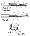
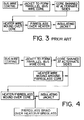
- prior art parallel zone heating cables provide a pair of bus wires 1, coated with insulation 2.
- the pair of insulated bus wires is then coated, while in a parallel state, with an insulator coat 3.
- the insulating coats 2 and 3 are stripped off of the bus wire, then the metal of the other bus wire, and so on.
- a heater wire 5 is then wound around the alternately stripped core to make electrical contact with the bus wires 1, to create heating circuits between the bus wires, corresponding to the distance between stripped locations on the bus wires.
- a fibreglass layer 6, which may be a woven braid or helically applied yarn, may then served over the heater wire.
- a final layer of insulation 7 is then extruded over the fibreglass layer, yielding a finished product.
- the present invention provides a different construction to achieve an end result that shares many basic characteristics of known parallel zone heating cables, but is an improvement over same.
- a similar core of parallel, untwisted and insulated 2 bus wires 1 is coated with an insulating jacket 3, and stripped at alternating locations 4.
- a heater wire 5 (see Figure 1) is then wound directly over the bus wire core
- a heater wire 9 (see Figure 2A) is wound over a fibreglass or other insulating core 10, and then the heater wire/fibreglass combination 9/10 is wound over the bus wire core.
- a fibreglass layer 11 may be braided over the heater wire/fibreglass combination, as shown in Figure 5.
- the heater wire 9 utilized in the present invention may be of very much smaller diameter than that of the prior art.
- This feature combined with the cushioning effect of the fibreglass core 10 provides a heating element combination that is very flexible and supple.
- such a combination because of the cushioning effect of fibreglass core 10, is capable of withstanding mechanical impacts associated with an individual installation environment and rapid heat and cooling cycles without breakage, unlike the heater wire of the prior art, that is wound directly onto the fairly unyielding bus wire core.
- a greater length of heater wire 9 is utilized, helically wrapped around a fibreglass core 10, equivalent heating characteristics with much shorter zone lengths are possible.
- This construction results in a cable having technical specifications that meet or exceed industry standards, with short zones and good impact resistance, as well as superior ability to withstand rapid heating cycling without breaking down.
- Bus wire 1 may be any desired, single or multi strand wire, as will be obvious to one skilled in the art.
- Insulating layers 2, 3, 7 may be FEP, PTFE, PFA, TPR, PVC, fibreglass, ceramic fibre, or any other suitable insulation.
- Heater wire 9 may be AWG 30 to AWG 48, and insulating core 10, as well as being fibreglass, may be polypropylene, polyester, ceramic fibres, or other suitable temperature rated material.
- the selection of heater wire 9 will depend on the desired characteristics and the intended use of the cable.
- a heater wire exhibiting positive temperature coefficient of resistance (PTC) is used, and in this regard, a minimum 60% nickel wire is desirable.
- the balance may be chrome, copper, or iron, or a combination thereof.
- 70% nickel to 99% nickel, remainder iron, alloy is utilized.
Landscapes
- Resistance Heating (AREA)
Applications Claiming Priority (2)
| Application Number | Priority Date | Filing Date | Title |
|---|---|---|---|
| CA 2174615 CA2174615A1 (en) | 1996-04-19 | 1996-04-19 | Variable power limiting heat tracing cable |
| CA2174615 | 1996-04-19 |
Publications (3)
| Publication Number | Publication Date |
|---|---|
| EP0802701A2 true EP0802701A2 (de) | 1997-10-22 |
| EP0802701A3 EP0802701A3 (de) | 1997-11-19 |
| EP0802701B1 EP0802701B1 (de) | 2000-02-02 |
Family
ID=4158030
Family Applications (1)
| Application Number | Title | Priority Date | Filing Date |
|---|---|---|---|
| EP19960303335 Expired - Lifetime EP0802701B1 (de) | 1996-04-19 | 1996-05-13 | Heizkabel mit variablem Leistungsbegrenzer |
Country Status (4)
| Country | Link |
|---|---|
| EP (1) | EP0802701B1 (de) |
| CA (1) | CA2174615A1 (de) |
| DE (1) | DE69606519T2 (de) |
| RU (1) | RU2180772C2 (de) |
Cited By (5)
| Publication number | Priority date | Publication date | Assignee | Title |
|---|---|---|---|---|
| WO2002067630A1 (de) * | 2001-02-16 | 2002-08-29 | Thermon Europe B.V. | Heizkabel mit mehrschichtaufbau |
| CN107071936A (zh) * | 2017-05-19 | 2017-08-18 | 佛山市高明毅力温控器有限公司 | 带编织网的绝缘电热线和电源线连接结构及其制造方法 |
| WO2019145780A1 (en) * | 2018-01-25 | 2019-08-01 | Zoppas Industries De Mexico S.A., De C.V. | Sheathed fiberglass heater wire |
| US10566113B2 (en) | 2014-07-23 | 2020-02-18 | Leoni Kabel Gmbh | Method for producing an electrical line, electrical line, and vehicle on-board power supply system having a corresponding electrical line |
| CN113571238A (zh) * | 2021-07-22 | 2021-10-29 | 安邦电气股份有限公司 | 一种船用耐腐蚀伴热电缆 |
Families Citing this family (3)
| Publication number | Priority date | Publication date | Assignee | Title |
|---|---|---|---|---|
| FR2921194B1 (fr) * | 2007-09-18 | 2010-03-12 | Acome Soc Coop Production | Cable autoregulant a comportement ctp et a puissance electrique modulable, son connecteur, un dispositif les comprenant et utilisation de ce dernier |
| US9881715B2 (en) | 2014-08-21 | 2018-01-30 | Trent Jason Pederson | Heated extension cord |
| CN109688640B (zh) * | 2019-01-29 | 2021-10-26 | 安徽环瑞电热器材有限公司 | 一种三层共挤伴热电缆及其制备系统 |
Family Cites Families (5)
| Publication number | Priority date | Publication date | Assignee | Title |
|---|---|---|---|---|
| AT309616B (de) * | 1970-07-14 | 1973-08-27 | Bleckmann & Co | Elektrischer Heizkörper und mit ihm ausgestattetes Heizgerät |
| US3859506A (en) * | 1973-06-15 | 1975-01-07 | Sola Basic Ind Inc | Constant wattage heating element |
| US4100673A (en) * | 1977-05-05 | 1978-07-18 | Leavines Joseph E | Method of making high temperature parallel resistance pipe heater |
| US5245161A (en) * | 1990-08-31 | 1993-09-14 | Tokyo Kogyo Boyeki Shokai, Ltd. | Electric heater |
| SU1823175A1 (ru) * | 1990-10-08 | 1996-04-20 | Донецкий государственный медицинский институт им.М.Горького | Способ доступа к сонным артериям при злокачественных опухолях челюстно-лицевой области |
-
1996
- 1996-04-19 CA CA 2174615 patent/CA2174615A1/en not_active Abandoned
- 1996-05-13 DE DE1996606519 patent/DE69606519T2/de not_active Expired - Lifetime
- 1996-05-13 EP EP19960303335 patent/EP0802701B1/de not_active Expired - Lifetime
- 1996-05-20 RU RU96109820A patent/RU2180772C2/ru active
Cited By (8)
| Publication number | Priority date | Publication date | Assignee | Title |
|---|---|---|---|---|
| WO2002067630A1 (de) * | 2001-02-16 | 2002-08-29 | Thermon Europe B.V. | Heizkabel mit mehrschichtaufbau |
| US10566113B2 (en) | 2014-07-23 | 2020-02-18 | Leoni Kabel Gmbh | Method for producing an electrical line, electrical line, and vehicle on-board power supply system having a corresponding electrical line |
| EP3172742B1 (de) * | 2014-07-23 | 2023-01-11 | LEONI Kabel GmbH | Verfahren zur herstellung einer elektrischen leitung, elektrische leitung sowie kraftfahrzeug-bordnetz mit einer entsprechenden elektrischen leitung |
| CN107071936A (zh) * | 2017-05-19 | 2017-08-18 | 佛山市高明毅力温控器有限公司 | 带编织网的绝缘电热线和电源线连接结构及其制造方法 |
| CN107071936B (zh) * | 2017-05-19 | 2023-04-28 | 佛山市高明毅力温控器有限公司 | 带编织网的绝缘电热线和电源线连接结构及其制造方法 |
| WO2019145780A1 (en) * | 2018-01-25 | 2019-08-01 | Zoppas Industries De Mexico S.A., De C.V. | Sheathed fiberglass heater wire |
| US11920853B2 (en) | 2018-01-25 | 2024-03-05 | Zoppas Industries De Mexico S.A., De C.V. | Sheathed fiberglass heater wire |
| CN113571238A (zh) * | 2021-07-22 | 2021-10-29 | 安邦电气股份有限公司 | 一种船用耐腐蚀伴热电缆 |
Also Published As
| Publication number | Publication date |
|---|---|
| RU2180772C2 (ru) | 2002-03-20 |
| EP0802701B1 (de) | 2000-02-02 |
| EP0802701A3 (de) | 1997-11-19 |
| DE69606519T2 (de) | 2000-10-19 |
| DE69606519D1 (de) | 2000-03-09 |
| CA2174615A1 (en) | 1997-10-20 |
Similar Documents
| Publication | Publication Date | Title |
|---|---|---|
| US6144018A (en) | Heating cable | |
| US5558794A (en) | Coaxial heating cable with ground shield | |
| JP2557910B2 (ja) | 可撓性の電気加熱要素およびその製造方法 | |
| EP0096492B1 (de) | Langgestreckte elektrische Heizelemente | |
| CA1301229C (en) | Flexible, elongated positive temperature coefficient heating assembly and method | |
| US4037083A (en) | High temperature parallel resistance pipe heater | |
| US4100673A (en) | Method of making high temperature parallel resistance pipe heater | |
| GB2130459A (en) | A flexible electrical heating or temperature measuring element | |
| KR101065115B1 (ko) | 선재 보호구조를 구비한 열선 케이블 | |
| EP1992199B1 (de) | Glasbeschichtete metallfilamentkabel zur verwendung in elektrisch heizbaren textilien | |
| JP2008311111A (ja) | コード状ヒータ | |
| EP0802701B1 (de) | Heizkabel mit variablem Leistungsbegrenzer | |
| USRE26522E (en) | Cold terminal electrical resistance heating cable | |
| WO1995004357A1 (en) | Improved dielectric miniature electric cable | |
| CA2089048C (en) | Heating cable with enhanced flexibility | |
| CA2205638C (en) | Flexible heat tracing cable with improved thermal characteristics | |
| CA1338315C (en) | Cut to length heater cable | |
| GB2110910A (en) | Electrical strip heater element | |
| RU96109820A (ru) | Нагревательный кабель | |
| JP7768886B2 (ja) | 導電線状ヒータ素子 | |
| GB2048626A (en) | An electrical heating tape | |
| JP4147290B2 (ja) | 温度ヒューズケーブル | |
| JP4360783B2 (ja) | 温度ヒューズケーブル | |
| EP2797383A1 (de) | Heizkabel | |
| KR200361390Y1 (ko) | 전열케이블 |
Legal Events
| Date | Code | Title | Description |
|---|---|---|---|
| PUAI | Public reference made under article 153(3) epc to a published international application that has entered the european phase |
Free format text: ORIGINAL CODE: 0009012 |
|
| PUAL | Search report despatched |
Free format text: ORIGINAL CODE: 0009013 |
|
| AK | Designated contracting states |
Kind code of ref document: A2 Designated state(s): DE FR GB IT NL |
|
| AK | Designated contracting states |
Kind code of ref document: A3 Designated state(s): DE FR GB IT NL |
|
| 17P | Request for examination filed |
Effective date: 19980422 |
|
| 17Q | First examination report despatched |
Effective date: 19980714 |
|
| GRAG | Despatch of communication of intention to grant |
Free format text: ORIGINAL CODE: EPIDOS AGRA |
|
| GRAG | Despatch of communication of intention to grant |
Free format text: ORIGINAL CODE: EPIDOS AGRA |
|
| GRAG | Despatch of communication of intention to grant |
Free format text: ORIGINAL CODE: EPIDOS AGRA |
|
| GRAH | Despatch of communication of intention to grant a patent |
Free format text: ORIGINAL CODE: EPIDOS IGRA |
|
| GRAH | Despatch of communication of intention to grant a patent |
Free format text: ORIGINAL CODE: EPIDOS IGRA |
|
| GRAA | (expected) grant |
Free format text: ORIGINAL CODE: 0009210 |
|
| AK | Designated contracting states |
Kind code of ref document: B1 Designated state(s): DE FR GB IT NL |
|
| REF | Corresponds to: |
Ref document number: 69606519 Country of ref document: DE Date of ref document: 20000309 |
|
| ITF | It: translation for a ep patent filed | ||
| ET | Fr: translation filed | ||
| PLBE | No opposition filed within time limit |
Free format text: ORIGINAL CODE: 0009261 |
|
| STAA | Information on the status of an ep patent application or granted ep patent |
Free format text: STATUS: NO OPPOSITION FILED WITHIN TIME LIMIT |
|
| 26N | No opposition filed | ||
| REG | Reference to a national code |
Ref country code: GB Ref legal event code: IF02 |
|
| PGFP | Annual fee paid to national office [announced via postgrant information from national office to epo] |
Ref country code: GB Payment date: 20130528 Year of fee payment: 18 Ref country code: DE Payment date: 20130530 Year of fee payment: 18 |
|
| PGFP | Annual fee paid to national office [announced via postgrant information from national office to epo] |
Ref country code: FR Payment date: 20130606 Year of fee payment: 18 Ref country code: NL Payment date: 20130526 Year of fee payment: 18 Ref country code: IT Payment date: 20130524 Year of fee payment: 18 |
|
| REG | Reference to a national code |
Ref country code: DE Ref legal event code: R119 Ref document number: 69606519 Country of ref document: DE |
|
| REG | Reference to a national code |
Ref country code: NL Ref legal event code: V1 Effective date: 20141201 |
|
| GBPC | Gb: european patent ceased through non-payment of renewal fee |
Effective date: 20140513 |
|
| REG | Reference to a national code |
Ref country code: DE Ref legal event code: R119 Ref document number: 69606519 Country of ref document: DE Effective date: 20141202 |
|
| PG25 | Lapsed in a contracting state [announced via postgrant information from national office to epo] |
Ref country code: NL Free format text: LAPSE BECAUSE OF NON-PAYMENT OF DUE FEES Effective date: 20141201 |
|
| REG | Reference to a national code |
Ref country code: FR Ref legal event code: ST Effective date: 20150130 |
|
| PG25 | Lapsed in a contracting state [announced via postgrant information from national office to epo] |
Ref country code: IT Free format text: LAPSE BECAUSE OF NON-PAYMENT OF DUE FEES Effective date: 20140513 Ref country code: DE Free format text: LAPSE BECAUSE OF NON-PAYMENT OF DUE FEES Effective date: 20141202 |
|
| PG25 | Lapsed in a contracting state [announced via postgrant information from national office to epo] |
Ref country code: FR Free format text: LAPSE BECAUSE OF NON-PAYMENT OF DUE FEES Effective date: 20140602 Ref country code: GB Free format text: LAPSE BECAUSE OF NON-PAYMENT OF DUE FEES Effective date: 20140513 |