EP0802385B1 - Echangeur de chaleur - Google Patents
Echangeur de chaleur Download PDFInfo
- Publication number
- EP0802385B1 EP0802385B1 EP19970302478 EP97302478A EP0802385B1 EP 0802385 B1 EP0802385 B1 EP 0802385B1 EP 19970302478 EP19970302478 EP 19970302478 EP 97302478 A EP97302478 A EP 97302478A EP 0802385 B1 EP0802385 B1 EP 0802385B1
- Authority
- EP
- European Patent Office
- Prior art keywords
- heat exchanger
- side member
- connectors
- header pipes
- connector
- Prior art date
- Legal status (The legal status is an assumption and is not a legal conclusion. Google has not performed a legal analysis and makes no representation as to the accuracy of the status listed.)
- Expired - Lifetime
Links
Images

Classifications
-
- F—MECHANICAL ENGINEERING; LIGHTING; HEATING; WEAPONS; BLASTING
- F28—HEAT EXCHANGE IN GENERAL
- F28F—DETAILS OF HEAT-EXCHANGE AND HEAT-TRANSFER APPARATUS, OF GENERAL APPLICATION
- F28F9/00—Casings; Header boxes; Auxiliary supports for elements; Auxiliary members within casings
- F28F9/02—Header boxes; End plates
- F28F9/0243—Header boxes having a circular cross-section
-
- F—MECHANICAL ENGINEERING; LIGHTING; HEATING; WEAPONS; BLASTING
- F28—HEAT EXCHANGE IN GENERAL
- F28F—DETAILS OF HEAT-EXCHANGE AND HEAT-TRANSFER APPARATUS, OF GENERAL APPLICATION
- F28F9/00—Casings; Header boxes; Auxiliary supports for elements; Auxiliary members within casings
- F28F9/001—Casings in the form of plate-like arrangements; Frames enclosing a heat exchange core
- F28F9/002—Casings in the form of plate-like arrangements; Frames enclosing a heat exchange core with fastening means for other structures
-
- F—MECHANICAL ENGINEERING; LIGHTING; HEATING; WEAPONS; BLASTING
- F28—HEAT EXCHANGE IN GENERAL
- F28F—DETAILS OF HEAT-EXCHANGE AND HEAT-TRANSFER APPARATUS, OF GENERAL APPLICATION
- F28F2220/00—Closure means, e.g. end caps on header boxes or plugs on conduits
-
- F—MECHANICAL ENGINEERING; LIGHTING; HEATING; WEAPONS; BLASTING
- F28—HEAT EXCHANGE IN GENERAL
- F28F—DETAILS OF HEAT-EXCHANGE AND HEAT-TRANSFER APPARATUS, OF GENERAL APPLICATION
- F28F2275/00—Fastening; Joining
- F28F2275/14—Fastening; Joining by using form fitting connection, e.g. with tongue and groove
- F28F2275/143—Fastening; Joining by using form fitting connection, e.g. with tongue and groove with pin and hole connections
Definitions
- the present invention relates to a heat exchanger, and more particularly to a heat exchanger having a bracket mechanism for attaching the heat exchanger to an external member.
- a bracket is provided for attaching and fixing the heat exchanger to an external member, for example, a frame or a body member of a vehicle.
- an external member for example, a frame or a body member of a vehicle.
- a bracket has been connected and fixed to a header pipe or another structural member of the heat exchanger by brazing or other methods.
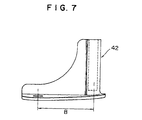
- brackets 41 and 42 are brazed to the lower end portions of header pipes 43 and 44 of heat exchanger body 45, respectively.
- Each of brackets 41 and 42 has a relatively complicated shape.
- Attaching portions 46 and 47 provided on the respective brackets 41 and 42 and formed as rod portions are attached and fixed to external members 48 and 49.
- brackets 41 and 42 must be designed depending upon the shape and size of heat exchanger body 45, many kinds of brackets having various sizes must be prepared and the shape of each bracket is likely to become relatively complicated. For example, if the dimension L between external members 48 and 49 is constant, many kinds of brackets having various sizes B must be prepared. Further, because brackets 41 and 42 must be designed depending upon the types of heat exchangers, restriction on design is great.
- brackes 41 and 42 are brazed to header pipes 43 and 44, usually the assembly of the heat exchanger is placed in a furnace. At that time, although brackes 41 and 42 are positioned relative to heat exchanger body 45 by jigs, various kinds of jigs must be prepared depending on the various kinds of brackets as well as relatively high skill is required for setting the jigs. Therefore, the heat exchanger having such a conventional structure is poor in assembling ability, and the percentage defective of brazing of brackets is relatively high.
- the material of the brackets 41 and 42 are limited to a material capable of being brazed to the heat exchanger body 45.
- a material of heat exchanger body 45 is an aluminum alloy
- the material of brackets 41 and 42 are limited to the identical material with or the same kind of material as the material of the heat exchanger body 45.
- brackets 41 and 42 are brazed to header pipes 43 and 44 over only a part of the peripheries of the header pipes 43 and 44 in the circumferential directions, also from this point, the percentage defective of brazing of brackets is likely to become relatively high, and the attachment strength of the heat exchanger becomes relatively low.
- brackets 41 and 42 are formed as separate members and they are not connected to each other, in a condition where the heat exchanger is attached to external members 48 and 49 via brackes 41 and 42, a stress due to an external force or vibration is liable to concentrate any one of the brackes 41 and 42 and the brazed surface thereof. Therefore, the attachment strength of the heat exchanger is relatively low.
- bracket forming member common to various types of heat exchangers as well as to simplify the shape of the bracket forming member, and to substantially remove limitation on material of the bracket forming member, thereby improving the assembling ability, decreasing the percentage defective in brazing and increasing the strength of the bracket itself and the strength of attachment of a heat exchanger.
- US-A-544110 discloses a heat exchanger with header pipes having pins for attachment to support brackets.
- a heat exchanger having a pair of header pipes; a connector connected to one end of each of the header pipes, said connectors each having a cylindrical portion having a header insertion hole and a side member formed separately from the connectors and having an attachment mechanism for attachment, in use to an external member characterised by the connectors each having a rectangular parallelopiped portion having a width smaller than a diameter of the cylindrical portion and a through hole; wherein, the side member is fixed, in use, to the rectangular parallelopiped portions of the said connector via fasteners inserted into the through hole, and wherein the side member extends within a region only between the header pipes.
- the connector may be brazed to the one end of the header pipe.
- the connector is constructed from material identical to that of the header pipe.
- the side member may be constructed from a material different from that of the connector. For example, when the connector is constructed from an aluminum-based material which is the same material as that of the header pipe, the side member may be constructed from an iron-based material.
- the heat exchanger according to the present invention is not particularly restricted as long as it has at least one header pipe, for example, it can be formed as a so-called multi-flow type heat exchanger having a pair of header pipes and a plurality of parallel tubes fluidly interconnected between the header pipes.
- a connector is connected to a lower end of each header pipe and the side member is provided to extend between both connectors.
- a conventional bracket for attachment which has been made depending on the types of heat exchangers is divided into a connector to be connected to an end of a header pipe and a side member to be fixed to the connector. Therefore, the connector may be formed as a shape capable of being fixed to the side member, and the shape of the connector can be simplified. At the same time, the shape of the side member formed as a separate member also can be simplified.
- the structure or shape of the connecting portion between the connector and the side member is made common, a common side member can be used even if the type of the heat exchanger is changed, and the restriction on design (shape) of the side member can be substantially removed.
- the side member is formed as a member separate from the connector, the limitation on material of the side member can be removed. Therefore, the strength of the side member itself, ultimately the strength of the bracket mechanism including the connector and the side member and the strength of attachment of the heat exchanger to an external member, can be greatly increased by using a high-strength material as the material of the side member, for example, an iron-system material.
- the shape of the connector itself can be simplified by the separate structure of the connector and the side member, the assembling ability of the connector to the header pipe and the side member to the connector can be greatly improved. Therefore, in brazing, the percentage defective on the brazing can be greatly decreased. Further, because the connector easily can be brazed simultaneously with the brazing of the heat exchanger body, the sub-assembly before the brazing may be substantially unnecessary or may be extremely simplified.
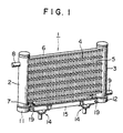
- FIG. 1 is a perspective view of a heat exchanger according an embodiment of the present invention.
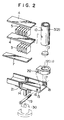
- FIG. 2 is an enlarged, exploded, partial perspective view of a bracket mechanism of the heat exchanger depicted in FIG. 1.
- FIG. 3 is an enlarged plan view of a connector of the heat exchanger depicted in FIG. 1.
- FIG. 4 is a side view of the connector depicted in FIG. 3.
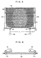
- FIG. 5 is a perspective view of a conventional heat exchanger.
- FIG. 6 is a bottom view of the heat exchanger depicted in FIG. 5.
- FIG. 7 is an enlarged side view of a bracket of the heat exchanger depicted in FIG. 5.
- Heat exchanger 1 in this embodiment is constructed as a multi-flow type heat exchanger.
- Heat exchanger 1 includes a pair of header pipes 2 and 3, a plurality of parallel heat transfer tubes 4 fluidly interconnected between the pair of header pipes 2 and 3 and a plurality of corrugated fins 5 disposed between on both surfaces of each heat transfer tube 4.
- each heat transfer tube 4 is formed as a flat tube. End plates 6 and 7 are provided on the upper surface of the uppermost fin 5 and on the lower surface of the lowermost fin 5, respectively.
- Inlet pipe 8 is connected to header pipe 2 and outlet pipe 9 is connected to header pipe 3, respectively.
- each end portion of each heat transfer tube 4 is inserted into a corresponding tube insertion hole 10 provided on header pipes 2 and 3, and connected to the header pipes 2 and 3.
- a heat medium for example, refrigerant, is introduced into header pipe 2 through inlet pipe 8, and after circulated in heat exchanger 1, it is discharged from header pipe 3 through outlet pipe 9.
- Connectors 11 and 12 are provided on the end portions of header pipes 2 and 3, respectively.
- each connector 11 or 12 is connected to the lower end of header pipe 2 or 3.
- Each connector 11 or 12 is formed from a rectangular parallelopiped portion 11a or 12a and a cylindrical portion 11b 12b, and has a through hole 20, an header insertion hole 23 and a through hole 24 formed at the bottom of the header insertion hole 23, as shown in FIGS. 3 and 4.
- the lower end portions of the respective header pipes 2 and 3 are inserted header insertion holes 23 of the respective connectors 11 and 12, and the connectors 11 and 12 are connected to the respective header pipes 2 and 3 over their entire circumferences.
- the connector 11 or 12 can be easily and precisely positioned relative to header pipe 2 or 3 by bringing the lower end surface of the header pipe 2 or 3 into contact with bottom surface 25 of header insertion hole 23 of the connector 11 or 12.
- These connectors 11 and 12 are made from the same kind of an aluminum-system material as that of header pipes 2 and 3. Connectors 11 and 12 are brazed to the lower ends of header pipes 2 and 3 each plugged by a cap 13, respectively.
- Side member 15 having an attachment mechanism 14 for being attached to an external member 30 is provided between connectors 11 and 12.
- Side member 15 is formed as a channel member and has a U-shaped cross section. Rectangular parallelopiped portion 11a or 12a of each connector 11 or 12 is positioned between the leg portions of the U-shaped cross section of side member 15.
- a through hole 16 and a screw hole 18 formed by connected nut 17 are provided on each end portion of side member 15, and through hole 20 is defined on rectangular parallelopiped portion 11a or 12a of each connector 11 or 12.
- bolt 19 is inserted into through hole 16 and through hole 20 and screwed into screw hole 18.
- side member 15 is fixed to both connectors 11 and 12.
- the fixing mechanism between side member 15 and connectors 11 and 12 is not particularly restricted, and other appropriate mechanisms may be employed.
- side member 15 is constructed from an iron-system material different from an aluminum-system material of connectors 11 and 12 and the heat exchanger body.
- the material of side member 15 is not particularly restricted to such an iron-system material, when another material is selected, it is preferred to select a high-strength material from the purpose of the present invention.
- attachment mechanism 14 to external member 30 is constructed from a supporting member 21 connected to the lower surface of side member 15 and a rod member 22 connected to the lower surface of the supporting member 21 and extending downward.
- Rod member 22 is engaged and fixed to external member 30, for example, a rubber vibration isolator.
- this attachment mechanism 14 also is not particularly restricted, and other appropriate mechanisms may be employed.
- the bracket mechanism for attachment of the heat exchanger 1 is divided into connectors 11 and 12 and side member 15. Since, for the shape of connectors 11 and 12, merely the connecting structure to header pipes 2 and 3 and the connecting structure to side member 15 may be considered, the shape of connectors 11 and 12 can be simplified. By this simplification of the shape of connectors 11 and 12, connectors 11 and 12 can be easily assembled to header pipes 2 and 3, and even in brazing, they can be easily brazed in a furnace simultaneously with the heat exchanger body and the percentage defective in the brazing can be decreased. Further, because of simple connectors 11 and 12, an extruded product, a forged product or a cast product can be applied for the manufacture of the connectors 11 and 12, thereby decreasing the manufacturing cost.
- connectors 11 and 12 and side member 15 can be greatly increased by the simple shapes of connectors 11 and 12 and side member 15 and the separate structure thereof.
- the limitation on material of side member 15 is substantially removed, and it is possible to make the side member 15 from a high-strength material such as an iron-system material.
- a high-strength material such as an iron-system material.
- each connector 11 (12) is connected and brazed to each header pipe 2 (3) over the entire periphery of the header pipe 2 (3) in the circumferential direction, the connection strength therebetween is very great. Moreover, because both connectors 11 and 12 are integrally connected by side member 15, the strength for attachment of the heat exchanger due to this bracket mechanism is very great.
- connectors 11 and 12 and side member 15 are constructed from different materials in the above-described embodiment, they may be constructed from the same kind of materials and the side member may be connected to the connectors by brazing. Even in such a structure, at least simplification of the shapes of the respective parts, increase of freedom on design due to the simplification of the shapes, improvement of assembling ability and decrease of percentage defective in brazing can be achieved.
Landscapes
- Engineering & Computer Science (AREA)
- Physics & Mathematics (AREA)
- Thermal Sciences (AREA)
- Mechanical Engineering (AREA)
- General Engineering & Computer Science (AREA)
- Details Of Heat-Exchange And Heat-Transfer (AREA)
- Heat-Exchange Devices With Radiators And Conduit Assemblies (AREA)
Claims (9)
- Echangeur de chaleur comportant une paire de tuyaux collecteurs (2, 3) ; un connecteur (11, 12) relié à une extrémité de chacun des tuyaux collecteurs (2, 3), ces connecteurs (11, 12) comportant chacun une partie cylindrique (11b, 12b) munie d'un trou d'introduction de collecteur (23) ; et un élément latéral (15) formé séparément des connecteurs (11, 12) et comportant un mécanisme de fixation (14) pour permettre la fixation, en cours d'utilisation, à un élément extérieur (30),
caractérisé en ce queles connecteurs comportent chacun une partie de parallélépipède rectangle (11a, 12a) présentant une largeur plus petite que le diamètre de la partie cylindrique (11b, 12b) et percée d'un trou traversant (20),l'élément latéral (15) est fixé, en cours d'utilisation, aux parties de parallélépipède rectangle (11a, 12a) du connecteur (11, 12) par des fixations (19) introduites dans le trou traversant (20), et l'élément latéral (15) ne s'étend que dans la zone comprise entre les tuyaux collecteurs (2, 3). - Echangeur de chaleur selon la revendication 1,
dans lequel
les connecteurs (11, 12) sont brasés à l'extrémité de chacun des tuyaux collecteurs (2, 3) sur toute la périphérie de chacun de ces tuyaux collecteurs (2, 3) dans la direction circonférentielle. - Echangeur de chaleur selon l'une quelconque des revendications précédentes,
dans lequel
les connecteurs (11, 12) sont fabriqués dans le même matériau que celui des tuyaux collecteurs (2, 3). - Echangeur de chaleur selon l'une quelconque des revendications précédentes,
dans lequel
l'élément latéral (15) est fabriqué dans un matériau différent de celui des connecteurs (11, 12). - Echangeur de chaleur selon la revendication 4,
dans lequel
les connecteurs (11, 12) sont fabriqués dans un matériau à base d'aluminium et l'élément latéral (15) est fabriqué dans un matériau à base de fer. - Echangeur de chaleur selon l'une quelconque des revendications précédentes,
dans lequel
l'élément latéral (15) présente une section transversale en forme de U. - Echangeur de chaleur selon l'une quelconque des revendications précédentes,
dans lequel
les fixations (19) sont des boulons. - Echangeur de chaleur selon l'une quelconque des revendications précédentes,
dans lequel
l'échangeur de chaleur est réalisé sous la forme d'un échangeur de chaleur multiflux comportant la paire de tuyaux collecteurs (2, 3) et un certain nombre de tubes parallèles (4) interconnectés par des liaisons de fluide entre la paire de tuyaux collecteurs (2, 3). - Echangeur de chaleur selon la revendication 8,
dans lequel
les connecteurs (11, 12) sont reliés à l'extrémité inférieure de chacun de la paire de tuyaux collecteurs (2, 3), et l'élément latéral (15) s'étend entre les deux parties de parallélépipède rectangle (11a, 12a) des deux connecteurs (11, 12).
Applications Claiming Priority (3)
| Application Number | Priority Date | Filing Date | Title |
|---|---|---|---|
| JP121091/96 | 1996-04-17 | ||
| JP12109196 | 1996-04-17 | ||
| JP12109196A JPH09280768A (ja) | 1996-04-17 | 1996-04-17 | 熱交換器 |
Publications (2)
| Publication Number | Publication Date |
|---|---|
| EP0802385A1 EP0802385A1 (fr) | 1997-10-22 |
| EP0802385B1 true EP0802385B1 (fr) | 2001-07-04 |
Family
ID=14802660
Family Applications (1)
| Application Number | Title | Priority Date | Filing Date |
|---|---|---|---|
| EP19970302478 Expired - Lifetime EP0802385B1 (fr) | 1996-04-17 | 1997-04-11 | Echangeur de chaleur |
Country Status (3)
| Country | Link |
|---|---|
| EP (1) | EP0802385B1 (fr) |
| JP (1) | JPH09280768A (fr) |
| DE (1) | DE69705454T2 (fr) |
Families Citing this family (2)
| Publication number | Priority date | Publication date | Assignee | Title |
|---|---|---|---|---|
| JP4089077B2 (ja) * | 1999-03-30 | 2008-05-21 | 株式会社デンソー | 熱交換器 |
| FR3028933B1 (fr) * | 2014-11-20 | 2019-08-16 | Valeo Systemes Thermiques | Dispositif de blocage pour bouteille d'echangeur de chaleur, bouteille, echangeur de chaleur et module comprenant un tel dispositif |
Family Cites Families (3)
| Publication number | Priority date | Publication date | Assignee | Title |
|---|---|---|---|---|
| US4367793A (en) * | 1977-03-18 | 1983-01-11 | Macintosh John J | Universal radiator assembly |
| JPH05332693A (ja) * | 1992-06-02 | 1993-12-14 | Showa Alum Corp | 熱交換器 |
| US5429182A (en) * | 1993-09-08 | 1995-07-04 | Showa Aluminum Corporation | Heat exchanger having inlet and outlet pipes for a heat exchanging medium and a method of making same |
-
1996
- 1996-04-17 JP JP12109196A patent/JPH09280768A/ja active Pending
-
1997
- 1997-04-11 DE DE1997605454 patent/DE69705454T2/de not_active Expired - Fee Related
- 1997-04-11 EP EP19970302478 patent/EP0802385B1/fr not_active Expired - Lifetime
Also Published As
| Publication number | Publication date |
|---|---|
| EP0802385A1 (fr) | 1997-10-22 |
| JPH09280768A (ja) | 1997-10-31 |
| DE69705454D1 (de) | 2001-08-09 |
| DE69705454T2 (de) | 2001-10-31 |
Similar Documents
| Publication | Publication Date | Title |
|---|---|---|
| US5127466A (en) | Heat exchanger with header bracket and insertable header plate | |
| US5265672A (en) | Heat exchanger | |
| JP3912836B2 (ja) | 熱交換器 | |
| US7156162B2 (en) | Unit-type heat exchanger | |
| AU644234B2 (en) | Heat exchanger | |
| JP2002081884A (ja) | 熱交換器の取付構造 | |
| JPH05332693A (ja) | 熱交換器 | |
| US5918667A (en) | Heat exchanger | |
| JP2000283689A (ja) | 熱交換器 | |
| JP3760571B2 (ja) | 熱交換器 | |
| EP0660063A2 (fr) | Echangeur de chaleur | |
| US5429181A (en) | Fastening device for a heat exchanger having a tubular header | |
| US5325914A (en) | Mounting bracket for a heat exchanger | |
| KR200184333Y1 (ko) | 열교환기 매니폴드용 시일장치 | |
| EP0802385B1 (fr) | Echangeur de chaleur | |
| US6776223B2 (en) | Heat exchanger having bracket mounted on side plate of core unit | |
| US20070062215A1 (en) | Condenser | |
| EP0805331A2 (fr) | Echangeur de chaleur multitubulaire | |
| EP1365204A1 (fr) | Changeur de chaleur | |
| EP1319908B1 (fr) | Echangeur thermique | |
| JPH0624702Y2 (ja) | 熱交換器 | |
| JP2831578B2 (ja) | ブラケットを備えた熱交換器の製造方法 | |
| EP1767889A2 (fr) | Echangeur de chaleur | |
| KR102855031B1 (ko) | 난류 발생을 이용한 고효율 오발형 핀 튜브 열교환기 | |
| JP2003207236A (ja) | 熱交換器 |
Legal Events
| Date | Code | Title | Description |
|---|---|---|---|
| PUAI | Public reference made under article 153(3) epc to a published international application that has entered the european phase |
Free format text: ORIGINAL CODE: 0009012 |
|
| AK | Designated contracting states |
Kind code of ref document: A1 Designated state(s): DE FR GB IT SE |
|
| 17P | Request for examination filed |
Effective date: 19980409 |
|
| 17Q | First examination report despatched |
Effective date: 20000322 |
|
| GRAG | Despatch of communication of intention to grant |
Free format text: ORIGINAL CODE: EPIDOS AGRA |
|
| GRAG | Despatch of communication of intention to grant |
Free format text: ORIGINAL CODE: EPIDOS AGRA |
|
| GRAH | Despatch of communication of intention to grant a patent |
Free format text: ORIGINAL CODE: EPIDOS IGRA |
|
| GRAH | Despatch of communication of intention to grant a patent |
Free format text: ORIGINAL CODE: EPIDOS IGRA |
|
| GRAA | (expected) grant |
Free format text: ORIGINAL CODE: 0009210 |
|
| AK | Designated contracting states |
Kind code of ref document: B1 Designated state(s): DE FR GB IT SE |
|
| REF | Corresponds to: |
Ref document number: 69705454 Country of ref document: DE Date of ref document: 20010809 |
|
| ITF | It: translation for a ep patent filed | ||
| ET | Fr: translation filed | ||
| REG | Reference to a national code |
Ref country code: GB Ref legal event code: IF02 |
|
| PGFP | Annual fee paid to national office [announced via postgrant information from national office to epo] |
Ref country code: SE Payment date: 20020405 Year of fee payment: 6 |
|
| PGFP | Annual fee paid to national office [announced via postgrant information from national office to epo] |
Ref country code: GB Payment date: 20020410 Year of fee payment: 6 Ref country code: FR Payment date: 20020410 Year of fee payment: 6 |
|
| PGFP | Annual fee paid to national office [announced via postgrant information from national office to epo] |
Ref country code: DE Payment date: 20020417 Year of fee payment: 6 |
|
| PLBE | No opposition filed within time limit |
Free format text: ORIGINAL CODE: 0009261 |
|
| STAA | Information on the status of an ep patent application or granted ep patent |
Free format text: STATUS: NO OPPOSITION FILED WITHIN TIME LIMIT |
|
| 26N | No opposition filed | ||
| PG25 | Lapsed in a contracting state [announced via postgrant information from national office to epo] |
Ref country code: GB Free format text: LAPSE BECAUSE OF NON-PAYMENT OF DUE FEES Effective date: 20030411 |
|
| PG25 | Lapsed in a contracting state [announced via postgrant information from national office to epo] |
Ref country code: SE Free format text: LAPSE BECAUSE OF NON-PAYMENT OF DUE FEES Effective date: 20030412 |
|
| PG25 | Lapsed in a contracting state [announced via postgrant information from national office to epo] |
Ref country code: DE Free format text: LAPSE BECAUSE OF NON-PAYMENT OF DUE FEES Effective date: 20031101 |
|
| EUG | Se: european patent has lapsed | ||
| GBPC | Gb: european patent ceased through non-payment of renewal fee |
Effective date: 20030411 |
|
| PG25 | Lapsed in a contracting state [announced via postgrant information from national office to epo] |
Ref country code: FR Free format text: LAPSE BECAUSE OF NON-PAYMENT OF DUE FEES Effective date: 20031231 |
|
| REG | Reference to a national code |
Ref country code: FR Ref legal event code: ST |
|
| PG25 | Lapsed in a contracting state [announced via postgrant information from national office to epo] |
Ref country code: IT Free format text: LAPSE BECAUSE OF NON-PAYMENT OF DUE FEES Effective date: 20050411 |