EP0802352A2 - Differential gear - Google Patents
Differential gear Download PDFInfo
- Publication number
- EP0802352A2 EP0802352A2 EP97106168A EP97106168A EP0802352A2 EP 0802352 A2 EP0802352 A2 EP 0802352A2 EP 97106168 A EP97106168 A EP 97106168A EP 97106168 A EP97106168 A EP 97106168A EP 0802352 A2 EP0802352 A2 EP 0802352A2
- Authority
- EP
- European Patent Office
- Prior art keywords
- side rotary
- output side
- rotary elements
- rollers
- elements
- Prior art date
- Legal status (The legal status is an assumption and is not a legal conclusion. Google has not performed a legal analysis and makes no representation as to the accuracy of the status listed.)
- Granted
Links
Images


Classifications
-
- F—MECHANICAL ENGINEERING; LIGHTING; HEATING; WEAPONS; BLASTING
- F16—ENGINEERING ELEMENTS AND UNITS; GENERAL MEASURES FOR PRODUCING AND MAINTAINING EFFECTIVE FUNCTIONING OF MACHINES OR INSTALLATIONS; THERMAL INSULATION IN GENERAL
- F16H—GEARING
- F16H48/00—Differential gearings
- F16H48/20—Arrangements for suppressing or influencing the differential action, e.g. locking devices
- F16H48/22—Arrangements for suppressing or influencing the differential action, e.g. locking devices using friction clutches or brakes
-
- F—MECHANICAL ENGINEERING; LIGHTING; HEATING; WEAPONS; BLASTING
- F16—ENGINEERING ELEMENTS AND UNITS; GENERAL MEASURES FOR PRODUCING AND MAINTAINING EFFECTIVE FUNCTIONING OF MACHINES OR INSTALLATIONS; THERMAL INSULATION IN GENERAL
- F16D—COUPLINGS FOR TRANSMITTING ROTATION; CLUTCHES; BRAKES
- F16D7/00—Slip couplings, e.g. slipping on overload, for absorbing shock
- F16D7/007—Slip couplings, e.g. slipping on overload, for absorbing shock the torque being transmitted and limited by rolling surfaces skidding, e.g. skew needle rollers
-
- F—MECHANICAL ENGINEERING; LIGHTING; HEATING; WEAPONS; BLASTING
- F16—ENGINEERING ELEMENTS AND UNITS; GENERAL MEASURES FOR PRODUCING AND MAINTAINING EFFECTIVE FUNCTIONING OF MACHINES OR INSTALLATIONS; THERMAL INSULATION IN GENERAL
- F16H—GEARING
- F16H48/00—Differential gearings
- F16H48/06—Differential gearings with gears having orbital motion
- F16H48/08—Differential gearings with gears having orbital motion comprising bevel gears
-
- F—MECHANICAL ENGINEERING; LIGHTING; HEATING; WEAPONS; BLASTING
- F16—ENGINEERING ELEMENTS AND UNITS; GENERAL MEASURES FOR PRODUCING AND MAINTAINING EFFECTIVE FUNCTIONING OF MACHINES OR INSTALLATIONS; THERMAL INSULATION IN GENERAL
- F16H—GEARING
- F16H48/00—Differential gearings
- F16H48/12—Differential gearings without gears having orbital motion
- F16H48/14—Differential gearings without gears having orbital motion with cams
- F16H48/147—Differential gearings without gears having orbital motion with cams with driven cam followers or balls engaging two opposite cams
Definitions
- the present invention relates generally to a differential gear permitting a difference in rotational speed between right and left or front and rear driving wheels of a motor vehicle.
- Conventional automotive differential gears are commonly of a type in which a pinion gear intervenes between a pair of bevel gears coupled to output shafts and the pinion gear is rotated upon a differential motion which may be caused by an application of external rotational force to the pinion gear shaft, to thereby permit the difference in rotational speed between the output shafts.
- Another type of differential gears are also known which have a differential motion restricting function for restraining one of the driving wheels from idling at the time of turning or during the traveling on the surface of road having a low frictional coefficient and in which a multiple disk clutch is disposed on the back side of the bevel gear and is pressed by a thrust force of the bevel gear to generate a frictional force, thereby achieving the transmission of a driving force.
- the present invention was conceived in view of the above problems. It is therefore the object of the present invention to provide a differential gear constantly ensuring a stable differential motion restricting force even at a lower rotational speed.
- a differential gear having an input side rotary element to be rotated by an external driving force, a pair of output side rotary elements arranged coaxially with the input side rotary element, and transmission means for transmitting a rotational force of the input side rotary element to the output side rotary elements while permitting a difference in rotational speed between the output side rotary elements
- the differential gear comprising a plurality of rollers interposed between axially confronting faces of the input side rotary element and at least one of the pair of output side rotary elements, the plurality of rollers when there occurs a difference in rotational speed between the pair of output side rotary elements being allowed to roll while being in contact with the confronting faces of the input and output side rotary elements; and a roller holder for holding the plurality of rollers at predetermined intervals in a freely rolling manner along a predetermined circumference around the rotational axes of the input side and output side rotary elements; wherein rolling axes of the
- a differential gear having an input side rotary element to be rotated by an external driving force, a pair of output side rotary elements arranged coaxially with the input side rotary element, a plurality of rolling elements interposed between axially confronting faces of the output side rotary elements, and a holder element for holding the rolling elements between the output side rotary elements, the holder element having a plurality of elongated holes extending in the radial direction of the output side rotary elements and extending therethrough in the axial direction of the output side rotary elements, the plurality of elongated holes movably receiving the rolling elements, the axially confronting faces of the output side rotary elements being provided with grooves with which the rolling elements are engaged, the grooves being continuous with each other in the circumferential direction of the output side rotary elements, the differential gear comprising a plurality of rollers interposed between axially confronting faces of the input side rotary element and at least one of the pair of output side rotary elements
- a differential gear having an input side rotary element to be rotated by an external driving force, a pair of output side rotary elements arranged coaxially with the input side rotary element, a plurality of rolling elements interposed between radially confronting faces of the input side rotary element and the output side rotary elements, and a holder element arranged axially movably between the radially confronting faces of the input side rotary element and the output side rotary elements, for holding in a freely rolling manner the rolling elements disposed in the axial direction of the output side rotary elements, the input side rotary element having a plurality of elongated holes extending in the axial direction of the output side rotary elements, the rolling elements movably engaging the plurality of elongated holes, the confronting faces of the output side rotary elements and the input side rotary element being provided with grooves with which the rolling elements are engaged, and which are continuous with each other in the circumferential direction of the output side rotary elements, the differential gear
- the rollers when there occurs a difference in rotational speed between the output side rotary elements, the rollers are allowed to roll while being in contact with the confronting faces of the input side and output side rotary elements, and move along the rotational trajectories of the output side rotary elements while being restricted by the holder from rolling to the direction inclined by a predetermined angle relative to the rotational trajectories of the output side rotary elements.
- a frictional force between the rollers and the contact surfaces therewith which results in a resistance to restrict the differential motions.
- the rollers generate a sliding frictional force in the course of rolling, so that it becomes possible to constantly obtain a stable frictional force even at a lower rotational speed, ensuring a secure prevention of noise and vibration.
- the frictional force can be varied in magnitude to obtain a desired differential motion restricting force.
- the plurality of rollers are preferably arranged in a freely inclined manner so that an angle formed, when there occurs a difference in rotational speed between the output side rotary elements in one direction of rotation, between the rolling axes of the rollers and a plane including the rotational axes of the input side and output side rotary elements, are different from an angle formed, when there occurs a difference in rotational speed between the output side rotary elements in the other direction of rotation, between the rolling axes of the rollers and the plane including rotational axes of the input side and output side rotary elements.
- a differential gear of this embodiment comprises a gear case 1, a gear case cover 2 serving to close one end of the gear case 1, a pair of bevel gears 3 arranged coaxially and confronting each other, a total of four pinion gears 4 interposed between the bevel gears 3, a pair of pressure rings 5 confronting each other with the bevel gears interposed, a pair of pressure plates 6 facing the back side of the pressure rings 5, a multiplicity of rollers 7 arranged between the pressure rings 5 and the pressure plates 6, and disk springs 8, 9 for urging the pressure plates 6 toward the pressure rings 5.
- An input side rotary element is constituted of the gear case 1, the gear case cover 2 and the pressure rings 5, whereas an output side rotary element is constituted of the bevel gears 3.
- the gear case 1 is of a tubular form having an open end and is provided at its center with a bearing 1a for supporting one of the bevel gears 3.
- a flange 1b which has a multiplicity of holes 1c for the insertion of bolts.
- a multiplicity of axially extending grooves 1d are formed in the inner surface of the gear case 1 in a circumferentially spaced apart relationship.
- the gear case cover 2 is of a disk-like form and is provided at its center a bearing 2a for supporting the other of the bevel gears 3.
- a flange 2b which has a multiplicity of holes 2c for the insertion of bolts. That is, the gear case cover 2 is mounted to the gear case 1 by means of the bolts not shown for fastening the flanges 1b and 2b together.
- the bevel gears 3 are arranged in such a manner as to allow their respective toothed sides to confront each other and are adapted to be linked with a drive shaft not shown on the wheel side.
- a multiplicity of axially extending grooves 3a are formed in the back side of the bevel gears 3 in a circumferentially spaced apart relationship.
- the pinion gears 4 are rotatably supported on pinion shafts 4a having longitudinal axis orthogonal to each other and are engaged with the bevel gears 3.
- the pressure rings 5 are so formed as to cover the bevel gears 3 and the pinion gears 4 from both end sides in the axial direction, and have on their outer peripheral surfaces a multiplicity of projections 5a spaced circumferentially apart from one another and intended to be fitted into the grooves 1d of the gear case 1.
- the confronting faces of the pressure rings 5 are each provided with a total of four V-shaped grooves 5b which are spaced circumferentially apart from one another. As shown in Fig. 5, the pinion shaft 4a is received in the grooves 5b of the pressure rings 5.
- the pressure plates 6 are each provided with a hole 6a which extends through the back side of the bevel gear 3 and which has an inner periphery provided with a multiplicity of protrusions 6b spaced circumerentially apart from one another and intended to be fitted into the grooves 3a of the bevel gear 3.
- the rollers 7 are each of a cylindrical form extending uniformly in the axial direction and are each held by an annular cage 7a at certain intervals in the circumferential direction.
- the cage 7a has a multiplicity of holes 7b for receiving the rollers 7 in such a manner as to allow their free rolling, the holes 7b as shown in Fig. 4B are provided in such a manner that rolling axes X of the rollers 7 are inclined by an angle theta relative to a plane including the rotational axis of the gear body, in other words, a line Y extending from the rotational center of the gear body.
- the disk springs 8, 9 are provided with holes 8a, 9a extending through the back side of the bevel gear 3, the hole 8a of the disk spring 8 on one hand having on its inner periphery a multiplicity of protrusions 8b intended to be fitted into the grooves 3a of the bevel gear 3, the disk spring 9 on the other hand having on its outer periphery a multiplicity of protrusions 9b intended to be fitted into the grooves 1d of the gear case 1.
- a ring gear not shown is attached to the flange 1b of the gear case 1 for the transmission of the driving force from an engine, thereby allowing the entire gear to rotate around the axis of the gear case 1. More specifically, when a driving force is inputted to the gear case 1, the driving force is transmitted from the gear case 1 to the pressure rings 5. The driving force transmitted to the pressure rings 5 is then delivered through the grooves 5b of the pressure rings 5 to the pinion shafts 4a, and further through the pinion gears 4 to the bevel gears 3.
- the rollers 7 roll while being in pressure contact with both the pressure rings 5 and the pressure plate 6, which is followed by the rotation of the cage 7a.
- the rollers 7 move along the rotational trajectory (direction indicated by a solid line) of the pressure plate 6 while being restricted by the cage 7a from rolling in the direction (the direction indicated by a chain dotted line) inclined by an angle theta relative to the rotational trajectory of the pressure plate 6, so that there occurs a frictional force corresponding to the thrust force F among the rollers 7 and the pressure ring 5 and the pressure plate 6, the frictional force serving as a resistance to restrict the differential motions between the bevel gears 3.
- rollers since the rollers generate sliding frictions while rolling, there is always obtained a stable frictional force arising from the dynamic friction, thereby ensuring that an instantaneous migration to the dynamic friction is achieved due to rolling of the rolls 7 even though static friction occurs at the initial stage.
- the rollers 7 are subjected also to load from a pilot pressure of the disk springs 8, 9 in addition to the thrust force F.
- a multiplicity of rollers 7 are caused to roll while being brought into pressure contact with the pressure ring 5 and the pressure plate 6 by the thrust force of the bevel gears 3, the axes of rolling of the rollers 7 being inclined at a predetermined angle relative to a plane including rotational axes of the bevel gears 3, to thereby generate a differential motion restricting force by the sliding friction accompanied by the rolling of the rollers 7, thus always ensuring an acquisition of a stable differential motion restricting force as well as securely preventing a generation of noise and vibration. Also, by setting the inclination angle theta of the rollers to an arbitrary angle to vary the magnitude of the frictional force, it is possible to obtain a desired differential motion restricting force.
- Figs. 8 and 9A, 9B illustrate a variant of the above embodiment, in which the rollers 7 are provided in a freely inclined manner. That is, a cage 7c shown in Figs. 8 and 9A, 9B has a multiplicity of holes 7d for receiving the rollers 7 so as to allow a free rolling, the holes 7d being fun-shaped starting from one end side of the roller 7, with both edges extending from the one end are inclined at different angles relative to the plane including the rotational axis of the gear body.
- the present invention is also applicable to the construction having no pressure rings 5 since the thrust force is generated also between the toothed faces of the bevel gears 3 and the pinion gears 4.
- Figs. 10 to 12 illustrate a second embodiment of the present invention
- Fig. 10 being a side sectional view of the differential gear
- Fig. 11 being a sectional view taken along a line 11-11 of Fig. 10 and viewed from the direction of arrow
- Fig. 12 being an exploded perspective view of the differential gear.
- This differential gear comprises a gear case 10, a gear case cover 11 serving to close one end of the gear case 10, a pair of disk plates 12 coaxially confronting each other, a center plate 13 interposed between the disk plate 12, a multiplicity of balls 14 held by the center plate so as to allow a free rolling, and a multiplicity of rollers 15 arranged on the back side of the disk plates 12.
- An input side rotary element is constituted of the gear case 10, the gear case cover 11 and the center plate 13.
- An output side rotary element is constituted of the disk plates 12.
- the gear case 10 is of a tubular form having one open end and is provided at its center with a bearing 10a for supporting one of the disk plates 12.
- a flange 10b which has a multiplicity of holes 10c for the insertion of bolts.
- the inner surface of the gear case 10 is provided with a groove 10d for securing the center plate 13.
- the gear case cover 11 is in the shape of a disk having at its center a bearing 11a for supporting the other of the disk plates 12.
- a flange 11b which has a multiplicity of holes 11c for the insertion of bolts. That is, the gear case cover 11 is mounted to the gear case 10 by means of bolts not shown for fastening the flanges 10b and 11b together.
- the disk plates 12 have their respective flat confronting faces, the other end thereof being provided with a coupling portion 12a for coupling a drive shaft not shown on the wheel side.
- the confronting faces of the disk plates 12 are provided with grooves 12b with which balls 14 are engaged in such a manner as to allow a free rolling, the grooves 12b being formed continuously in the circumferential direction.
- the grooves 12b each have a first guide segment 12b-1 in which the balls 14 are moved from the radially inner side of the disk plate 12 toward the outer side, and a second guide segment 12b-2 in which the balls 14 are moved from the radially outer side toward the inner side of the disk plate 12, the first and second guide segments being continuous in the circumferential direction.
- the first guide segment 12b-1 has a circumferential length greater than that of the second guide segment 12b-2
- the second guide segment 12b-2 has a circumferential length greater than that of the first guide segment 12b-1. That is, the arrangement of the confronting faces of the disk plates 12 is such that when the positions where the balls 14 are reversed coincide with each other on one side (outer side in the diagram) of the grooves 12b as shown in Fig. 11, then they are circumferentially shifted from each other on the other side (inner side of the diagram).
- the center plat 13 has flat end faces and a peripheral surface provided with a projection 13a intended to be fitted into the groove 10d formed in the inner peripheral surface of the gear case 10, to thereby secure the center plate 13 to the interior of the gear case 10.
- the center plate 13 has a multiplicity of elongated holes 13b which are spaced circumferentially equally apart from each other and which are intended to receive the balls 14 in such a manner as to allow the balls 14 to freely roll, the elongated holes 13 rectilinearly extending in the radial direction and passing therethrough in the axial direction.
- the balls 14 are received within the elongated holes 13b of the center plate 13 and are engaged with the grooves 12b of the disk plates 12.
- the rollers 15 are each in the form of a cylinder which extends uniformly in the axial direction and are retained by an annular cage 15a at certain intervals in the circumferential direction.
- the cage 15a has a multiplicity of hole 15b for receiving the rollers 15 in such a manner as to allow the rollers 15 to freely roll. Similar to the first embodiment, the holes 15b are so arranged that the rolling axes of the rollers 15 are inclined at predetermined angles relative to a plane including the rotational axis of the gear body.
- a ring gear not shown is attached to the flange 10b of the gear case 10 for transmitting a driving force from the engine so as to allow the entire gear to rotate around the axis of the gear case 10. More specifically, when a driving force is applied to the gear case 10, the center plate 13 is rotated together with the gear case 10, the resulting rotational force being transmitted through the balls 14 to the grooves 12b of the disk plates 12 and further to the drive shafts not shown coupled to the disk plates 12.
- the balls 14 within the elongated holes 13b are guided by the grooves 12b and roll to reciprocate along the associated elongated holes 13b. More specifically, the balls 14 lying on the radially outer side in Fig. 11 are moved toward the radially inner side along the first guide segments 12b-1 of the grooves 12b and after having reached the inner reversing points they are moved toward the radially outer side along the second guide segments 12b-2 of the grooves 12b. In this case, as shown in Fig.
- every other ball 14, that is, half of all the balls 14 is allowed to reach the outer reversing points of the grooves 12b although the remaining half of the balls 14 is not allowed to reach the inner reversing points since the arrangement of the confronting faces is such that when either the inner or outer reversing points of the grooves 12b coincide with each other, the remaining reversing points are shifted from each other. That is, when the balls 14 reach the reversing points of the grooves 12b, a force is not to be transmitted between the balls 14 and the grooves 12b, so that it must be prevented that all the balls 14 reach at the same time the reversing points of the grooves 12b.
- rollers 15 may be disposed in a freely inclined manner so as to increase the differential motion restricting force when a differential motion between the disk plates 12 occurs in one rotational direction, but to reduce the differential motion restricting force when it occurs in the other rotational direction.
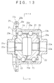
- Figs. 13 to 16 illustrate a third embodiment of the present invention
- Fig. 13 being a side sectional view of the differential gear
- Fig. 14 being a sectional view taken along the line 14-14 of Fig. 13 and viewed from the direction of arrow
- Fig. 15 being an exploded perspective view of the differential gear.
- the differential gear of this embodiment comprises a gear case 20, a gear case cover 21 for closing one end of the gear case 20, a pair of ball disks 22 arranged coaxially with each other, a multiplicity of ball holders 23 interposed between the ball disks 22, a multiplicity of balls 24 held by the ball holders 23 in such a manner as to allow the balls 24 to freely roll, a multiplicity of rollers 25 arranged on the back side of the ball disks 22, and a multiplicity of rollers 26 interposed between the ball disks 22.
- An input side rotary element is constituted of the gear case 20, the gear case cover 21 and the ball holders 23.
- An output side rotary element is constituted of the ball disks 22.
- the gear case 20 is of a tubular form having one open end and is provided at its center with a bearing 20a for supporting one of the ball disks 22.
- a flange 20b which has a multiplicity of holes 20c for the insertion of bolts.
- the inner peripheral surface of the gear case 20 is provided with a multiplicity of grooves 20d for engaging the balls 24, the grooves 20d extending rectilinearly in the axial direction of the gear case 20 and circumferentially equally spaced apart from each other.
- the gear case cover 21 is in the shape of a disk having at its center a bearing 22a for supporting the other of the ball disks 22.
- a flange 21b which has a multiplicity of holes 21c for the insertion of bolts. That is, the gear case cover 21 is mounted to the gear case 20 by means of bolts not shown for fastening the flanges 20b and 21b together.
- the ball disks 22 are each of a cylindrical form having at it one end a coupling portion 22a for coupling a drive shaft not shown.
- the ball disks 22 have the same outer diameter and their respective confronting end faces.
- the outer peripheral surfaces of the ball disks 22 are provided with grooves 22b with which the balls 24 are engaged in a freely rolling manner, the grooves 22b being continuous in the circumferential direction.
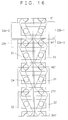
- Fig. 16 is a planar development of the ball disks 22, in which angles 0 to 360 degrees indicate circumferential positions.
- the grooves 22b alternately have a first guide segment 22b-1 in which the balls 24 are moved from the axially one side of the ball disk 22 toward the other side, and a second guide segment 22b-2 in which the balls 24 are moved from the axially other side of the ball disk 22 toward the one side, the first and second guide segments being continuous with each other.
- the first guide segment 22b-1 has a circumferential length greater than that of the second guide segment 22b-2
- the second guide segment 22b-2 has a circumferential length greater than that of the first guide segment 22b-1.
- the arrangement of the ball disks 22 is such that when the positions where the balls 14 are reversed coincide with each other on one side in the axial direction of the grooves 22b, then they are circumferentially shifted from each other on the other side.
- the ball holders 23 is in the form of a plate extending from the peripheral surface of the ball disk 22 on one hand to the peripheral surface of the ball disk 22 on the other hand and is slidably disposed between the gear case 20 and the ball disks 22.
- Each of the ball holders 23 has a total of two holes 23a for receiving a ball 24 on one ball disk 22 and a ball 24 on the other ball disk 22, respectively, and reciprocates in the axial direction of the ball disks 22 while keeping the balls 24 on the respective ball disks 22 at certain intervals.
- the balls 24 are received in the holes 23a of the ball holders 23 and are each engaged with both the groove 20d of the gear case 20 and the grooves 22b of the ball disks 22.
- the rollers 25, 26 are each in the form of a cylinder extending uniformly in the axial direction and are held by annular cages 25a, 26a at circumferentially certain intervals.
- the cages 25a and 26a are provided with a multiplicity of holes 25b and 26b, respectively, for receiving the rollers 25 and 26 in such a manner as to allow the rollers to freely roll.
- the holes 25b, 26b are so arranged that the rolling axes of the rollers 25, 26 are inclined by a predetermined angle relative to a plane including the rotational axis of the gear body.
- a ring gear not shown is mounted to the flange 20b of the gear case 20, for transmitting the driving force from the engine so as to rotate the entire gear around the axis of the gear case 20. That is, when a driving force is applied to the gear case 20, the ball holders 23 rotate integrally with the gear case 20, the resultant rotational force being transmitted through the balls 24 to the grooves 22b of the ball disks 22 and further to the drive shaft not shown coupled to the ball disks 22.
- the balls 24 are guided by the grooves 22b of the ball disks 22 and roll to reciprocate in the axial direction of the ball disks 22 along with the ball holders 23.
- the thrust force acts in the same direction (direction of both ends of the rotational axis) in spite of different transmitting directions of driving force, in the construction of this embodiment the directions in which the thrust force acts will also differ when the driving forces are transmitted in the different directions.
- the balls 24 within the grooves 22b come into contact with the axially outer side of the ball disks 22, allowing the ball disks 22 to generate a thrust force toward the axially outer side, so that a frictional force is generated by the rollers 25 lying on the back side of the ball disks 22.
- the balls 24 within the grooves 22b come into contact with the axially inner side of the ball disks 22, allowing the ball disks 22 to generate a thrust force toward the axially inner side, so that a frictional force is generated by the rollers 26 lying between the ball disks 22.
Landscapes
- Engineering & Computer Science (AREA)
- General Engineering & Computer Science (AREA)
- Mechanical Engineering (AREA)
- Retarders (AREA)
Abstract
Description
- The present invention relates generally to a differential gear permitting a difference in rotational speed between right and left or front and rear driving wheels of a motor vehicle.
- Conventional automotive differential gears are commonly of a type in which a pinion gear intervenes between a pair of bevel gears coupled to output shafts and the pinion gear is rotated upon a differential motion which may be caused by an application of external rotational force to the pinion gear shaft, to thereby permit the difference in rotational speed between the output shafts. Another type of differential gears are also known which have a differential motion restricting function for restraining one of the driving wheels from idling at the time of turning or during the traveling on the surface of road having a low frictional coefficient and in which a multiple disk clutch is disposed on the back side of the bevel gear and is pressed by a thrust force of the bevel gear to generate a frictional force, thereby achieving the transmission of a driving force.
- For mechanisms such as the multiple disk clutch making use of a sliding friction for the power transmission, however, it was extremely difficult to limit the frictional force in a half-coupled state to a certain value. At the lower rotational speed, in particular, the differential motion restricting force has disadvantageously suffered from significant instability including an occurrence of so-called stick slip, that is, intermittent generation of static friction and dynamic friction on clutch-to-clutch basis. Furthermore, an unstable frictional force will result in a generation of noise and vibration, which may adversely affect the running properties.
- The present invention was conceived in view of the above problems. It is therefore the object of the present invention to provide a differential gear constantly ensuring a stable differential motion restricting force even at a lower rotational speed.
- According to a first aspect of the present invention, in order to accomplish the above object, there is provided a differential gear having an input side rotary element to be rotated by an external driving force, a pair of output side rotary elements arranged coaxially with the input side rotary element, and transmission means for transmitting a rotational force of the input side rotary element to the output side rotary elements while permitting a difference in rotational speed between the output side rotary elements, the differential gear comprising a plurality of rollers interposed between axially confronting faces of the input side rotary element and at least one of the pair of output side rotary elements, the plurality of rollers when there occurs a difference in rotational speed between the pair of output side rotary elements being allowed to roll while being in contact with the confronting faces of the input and output side rotary elements; and a roller holder for holding the plurality of rollers at predetermined intervals in a freely rolling manner along a predetermined circumference around the rotational axes of the input side and output side rotary elements; wherein rolling axes of the rollers are inclined by predetermined angles relative to a plane including rotational axes of the input side and output side rotary elements.
- According to a second aspect of the present invention, there is provided a differential gear having an input side rotary element to be rotated by an external driving force, a pair of output side rotary elements arranged coaxially with the input side rotary element, a plurality of rolling elements interposed between axially confronting faces of the output side rotary elements, and a holder element for holding the rolling elements between the output side rotary elements, the holder element having a plurality of elongated holes extending in the radial direction of the output side rotary elements and extending therethrough in the axial direction of the output side rotary elements, the plurality of elongated holes movably receiving the rolling elements, the axially confronting faces of the output side rotary elements being provided with grooves with which the rolling elements are engaged, the grooves being continuous with each other in the circumferential direction of the output side rotary elements, the differential gear comprising a plurality of rollers interposed between axially confronting faces of the input side rotary element and at least one of the pair of output side rotary elements, the plurality of rollers when there occurs a difference in rotational speed between the pair of output side rotary elements being allowed to roll while being in contact with the confronting faces of the input and output side rotary elements; and
a roller holder for holding the plurality of rollers at predetermined intervals in a freely rolling manner along a predetermined circumference around the rotational axes of the input side and output side rotary elements, wherein rolling axes of the rollers are inclined by predetermined angles relative to a plane including rotational axes of the input side and output side rotary elements. - According to a third aspect of the present invention, there is provided a differential gear having an input side rotary element to be rotated by an external driving force, a pair of output side rotary elements arranged coaxially with the input side rotary element, a plurality of rolling elements interposed between radially confronting faces of the input side rotary element and the output side rotary elements, and a holder element arranged axially movably between the radially confronting faces of the input side rotary element and the output side rotary elements, for holding in a freely rolling manner the rolling elements disposed in the axial direction of the output side rotary elements, the input side rotary element having a plurality of elongated holes extending in the axial direction of the output side rotary elements, the rolling elements movably engaging the plurality of elongated holes, the confronting faces of the output side rotary elements and the input side rotary element being provided with grooves with which the rolling elements are engaged, and which are continuous with each other in the circumferential direction of the output side rotary elements, the differential gear comprising a plurality of rollers interposed between axially confronting faces of the input side rotary element and the pair of output side rotary elements and between axially confronting faces of the output side rotary elements, the plurality of rollers when there occurs a difference in rotational speed between the pair of output side rotary elements being allowed to roll while being in contact with the confronting faces of the input and output side rotary elements and with the confronting faces of the output side rotary elements; and a roller holder for holding the plurality of rollers at predetermined intervals in a freely rolling manner along a predetermined circumference around the rotational axes of the input side and output side rotary elements; wherein rolling axes of the rollers are inclined by predetermined angles relative to a plane including rotational axes of the input side and output side rotary elements.
- In the above differential gear, when there occurs a difference in rotational speed between the output side rotary elements, the rollers are allowed to roll while being in contact with the confronting faces of the input side and output side rotary elements, and move along the rotational trajectories of the output side rotary elements while being restricted by the holder from rolling to the direction inclined by a predetermined angle relative to the rotational trajectories of the output side rotary elements. Thus, there is generated a frictional force between the rollers and the contact surfaces therewith, which results in a resistance to restrict the differential motions. At that time, the rollers generate a sliding frictional force in the course of rolling, so that it becomes possible to constantly obtain a stable frictional force even at a lower rotational speed, ensuring a secure prevention of noise and vibration. In addition, by setting the inclination angles of the rollers to arbitrary values, the frictional force can be varied in magnitude to obtain a desired differential motion restricting force.
- In the differential gear set forth hereinabove, the plurality of rollers are preferably arranged in a freely inclined manner so that an angle formed, when there occurs a difference in rotational speed between the output side rotary elements in one direction of rotation, between the rolling axes of the rollers and a plane including the rotational axes of the input side and output side rotary elements, are different from an angle formed, when there occurs a difference in rotational speed between the output side rotary elements in the other direction of rotation, between the rolling axes of the rollers and the plane including rotational axes of the input side and output side rotary elements. Thus, different inclination angles of the rollers will lead to different magnitudes of frictional force, making it possible to increase the differential motion restricting force when in one rotational direction there occurs a difference in rotational speed between the output side rotary elements but to reduce the differential motion restricting force when it occurs in the other rotational direction.
- The above and other objects, aspects, features and advantages of the present invention will become more apparent from the following detailed description with reference to the accompanying drawings, in which:
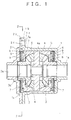
- Fig. 1 is a side sectional view of a differential gear showing a first embodiment of the present invention;
- Fig. 2 is a sectional view taken along a line 2-2 of Fig. 1 and viewed from the direction of the arrow;
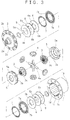
- Fig. 3 is an exploded perspective view of the differential gear;
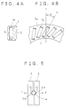
- Figs. 4A and 4B are enlarged views of major parts of the differential gear;
- Fig. 5 is an explanatory diagram of operation of the differential gear;
- Fig. 6 is an explanatory diagram of operation showing a principle of generation of a frictional force;
- Fig. 7 is an explanatory diagram of operation showing a principle of generation of a frictional force;
- Fig. 8 is a front elevational view of a major part showing a variant of the first embodiment;
- Figs. 9A and 9B are explanatory diagrams of operation of rollers;
- Fig. 10 is a side sectional view of a differential gear showing a second embodiment of the present invention;
- Fig. 11 is a sectional view taken along a line 11-11 of Fig. 10 and viewed from the direction of the arrow;
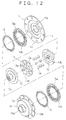
- Fig. 12 is an exploded perspective view of the differential gear;
- Fig. 13 is a side sectional view of a differential gear showing a third embodiment of the present invention;
- Fig. 14 is a sectional view taken along a line 14-14 of Fig. 13 and viewed from the direction of the arrow;
- Fig. 15 is an exploded perspective view of the differential gear; and
- Fig. 16 is a development view of grooves.
- A differential gear of this embodiment comprises a
gear case 1, agear case cover 2 serving to close one end of thegear case 1, a pair ofbevel gears 3 arranged coaxially and confronting each other, a total of fourpinion gears 4 interposed between thebevel gears 3, a pair ofpressure rings 5 confronting each other with the bevel gears interposed, a pair ofpressure plates 6 facing the back side of thepressure rings 5, a multiplicity ofrollers 7 arranged between thepressure rings 5 and thepressure plates 6, anddisk springs pressure plates 6 toward thepressure rings 5. An input side rotary element is constituted of thegear case 1, thegear case cover 2 and thepressure rings 5, whereas an output side rotary element is constituted of thebevel gears 3. - The
gear case 1 is of a tubular form having an open end and is provided at its center with abearing 1a for supporting one of thebevel gears 3. Around thegear case 1 is provided aflange 1b which has a multiplicity ofholes 1c for the insertion of bolts. A multiplicity of axially extendinggrooves 1d are formed in the inner surface of thegear case 1 in a circumferentially spaced apart relationship. - The
gear case cover 2 is of a disk-like form and is provided at its center abearing 2a for supporting the other of thebevel gears 3. Around thegear case cover 2 is provided aflange 2b which has a multiplicity ofholes 2c for the insertion of bolts. That is, thegear case cover 2 is mounted to thegear case 1 by means of the bolts not shown for fastening theflanges - The
bevel gears 3 are arranged in such a manner as to allow their respective toothed sides to confront each other and are adapted to be linked with a drive shaft not shown on the wheel side. A multiplicity of axially extendinggrooves 3a are formed in the back side of thebevel gears 3 in a circumferentially spaced apart relationship. - The
pinion gears 4 are rotatably supported onpinion shafts 4a having longitudinal axis orthogonal to each other and are engaged with thebevel gears 3. - The
pressure rings 5 are so formed as to cover thebevel gears 3 and thepinion gears 4 from both end sides in the axial direction, and have on their outer peripheral surfaces a multiplicity ofprojections 5a spaced circumferentially apart from one another and intended to be fitted into thegrooves 1d of thegear case 1. The confronting faces of thepressure rings 5 are each provided with a total of four V-shaped grooves 5b which are spaced circumferentially apart from one another. As shown in Fig. 5, thepinion shaft 4a is received in thegrooves 5b of thepressure rings 5. - The
pressure plates 6 are each provided with ahole 6a which extends through the back side of thebevel gear 3 and which has an inner periphery provided with a multiplicity ofprotrusions 6b spaced circumerentially apart from one another and intended to be fitted into thegrooves 3a of thebevel gear 3. - As shown in Fig. 4A, 4B, the
rollers 7 are each of a cylindrical form extending uniformly in the axial direction and are each held by anannular cage 7a at certain intervals in the circumferential direction. Thecage 7a has a multiplicity ofholes 7b for receiving therollers 7 in such a manner as to allow their free rolling, theholes 7b as shown in Fig. 4B are provided in such a manner that rolling axes X of therollers 7 are inclined by an angle theta relative to a plane including the rotational axis of the gear body, in other words, a line Y extending from the rotational center of the gear body. - The
disk springs holes bevel gear 3, thehole 8a of thedisk spring 8 on one hand having on its inner periphery a multiplicity ofprotrusions 8b intended to be fitted into thegrooves 3a of thebevel gear 3, thedisk spring 9 on the other hand having on its outer periphery a multiplicity ofprotrusions 9b intended to be fitted into thegrooves 1d of thegear case 1. - In the thus constructed differential gear, a ring gear not shown is attached to the
flange 1b of thegear case 1 for the transmission of the driving force from an engine, thereby allowing the entire gear to rotate around the axis of thegear case 1. More specifically, when a driving force is inputted to thegear case 1, the driving force is transmitted from thegear case 1 to the pressure rings 5. The driving force transmitted to the pressure rings 5 is then delivered through thegrooves 5b of the pressure rings 5 to thepinion shafts 4a, and further through the pinion gears 4 to the bevel gears 3. - Then, if a difference in rotational speed occurs between the
bevel gears 3, the pinion gears 4 rotate to achieve differential motions between the bevel gears 3. At that time, thepressure plates 6 and thedisk spring 8 on one hand rotate together respectively with thebevel gears 3, whereas thedisk spring 9 on the other hand rotates together with thegear case 1. As shown in Fig. 5, due to an inclination of contact faces of thegrooves 5b of the pressure rings 5 with thepinion shaft 4a relative to the input direction of the driving force, when the driving force input to thegear case 1 is transmitted to the pressure rings 5, a thrust force F will be generated as a result of thepressure ring 5 being urged to move in the direction of the rotational axis. Thus, as shown in Fig. 6, therollers 7 roll while being in pressure contact with both the pressure rings 5 and thepressure plate 6, which is followed by the rotation of thecage 7a. As shown in Fig. 7, at that time, therollers 7 move along the rotational trajectory (direction indicated by a solid line) of thepressure plate 6 while being restricted by thecage 7a from rolling in the direction (the direction indicated by a chain dotted line) inclined by an angle theta relative to the rotational trajectory of thepressure plate 6, so that there occurs a frictional force corresponding to the thrust force F among therollers 7 and thepressure ring 5 and thepressure plate 6, the frictional force serving as a resistance to restrict the differential motions between the bevel gears 3. In this case, since the rollers generate sliding frictions while rolling, there is always obtained a stable frictional force arising from the dynamic friction, thereby ensuring that an instantaneous migration to the dynamic friction is achieved due to rolling of therolls 7 even though static friction occurs at the initial stage. Therollers 7 are subjected also to load from a pilot pressure of the disk springs 8, 9 in addition to the thrust force F. - According to the differential gear of this embodiment in this manner, a multiplicity of
rollers 7 are caused to roll while being brought into pressure contact with thepressure ring 5 and thepressure plate 6 by the thrust force of thebevel gears 3, the axes of rolling of therollers 7 being inclined at a predetermined angle relative to a plane including rotational axes of thebevel gears 3, to thereby generate a differential motion restricting force by the sliding friction accompanied by the rolling of therollers 7, thus always ensuring an acquisition of a stable differential motion restricting force as well as securely preventing a generation of noise and vibration. Also, by setting the inclination angle theta of the rollers to an arbitrary angle to vary the magnitude of the frictional force, it is possible to obtain a desired differential motion restricting force. - Figs. 8 and 9A, 9B illustrate a variant of the above embodiment, in which the
rollers 7 are provided in a freely inclined manner. That is, acage 7c shown in Figs. 8 and 9A, 9B has a multiplicity ofholes 7d for receiving therollers 7 so as to allow a free rolling, theholes 7d being fun-shaped starting from one end side of theroller 7, with both edges extending from the one end are inclined at different angles relative to the plane including the rotational axis of the gear body. - In the above construction, if there occurs a difference in rotational speed between the
pressure ring 5 and thepressure plate 6 in one of the rotational directions as shown in Fig. 9A, then therollers 7 roll in a state where they have been tilted toward the one end of thecage 7c. If there occurs a difference in rotational speed between thepressure ring 5 and thepressure plate 6 in the other of the rotational directions as shown in Fig. 9B, then therollers 7 roll in a state where they have been tilted toward the other end of thecage 7c. At that time, the inclination angles of therollers 7 differ depending on the rotational directions of thepressure ring 5 and thepressure plate 6, so that different frictional forces will occur depending on their respective angles of inclination. It is therefore possible to increase the differential motion restricting force when the differential motion of thebevel gears 3 occurs in the one rotational direction, but to decrease the force when it occurs in the other rotational direction, which will be advantageous to the mechanism requiring such operations. - Although a thrust force has been generated by means of the pressure rings 5 in the above embodiment, the present invention is also applicable to the construction having no pressure rings 5 since the thrust force is generated also between the toothed faces of the
bevel gears 3 and the pinion gears 4. - Figs. 10 to 12 illustrate a second embodiment of the present invention, Fig. 10 being a side sectional view of the differential gear, Fig. 11 being a sectional view taken along a line 11-11 of Fig. 10 and viewed from the direction of arrow, and Fig. 12 being an exploded perspective view of the differential gear.
- This differential gear comprises a
gear case 10, a gear case cover 11 serving to close one end of thegear case 10, a pair ofdisk plates 12 coaxially confronting each other, acenter plate 13 interposed between thedisk plate 12, a multiplicity ofballs 14 held by the center plate so as to allow a free rolling, and a multiplicity ofrollers 15 arranged on the back side of thedisk plates 12. An input side rotary element is constituted of thegear case 10, thegear case cover 11 and thecenter plate 13. An output side rotary element is constituted of thedisk plates 12. - The
gear case 10 is of a tubular form having one open end and is provided at its center with abearing 10a for supporting one of thedisk plates 12. Around thegear case 10 there is provided aflange 10b which has a multiplicity ofholes 10c for the insertion of bolts. The inner surface of thegear case 10 is provided with agroove 10d for securing thecenter plate 13. - The gear case cover 11 is in the shape of a disk having at its center a
bearing 11a for supporting the other of thedisk plates 12. Around the gear case cover 11 there is formed aflange 11b which has a multiplicity ofholes 11c for the insertion of bolts. That is, the gear case cover 11 is mounted to thegear case 10 by means of bolts not shown for fastening theflanges - The
disk plates 12 have their respective flat confronting faces, the other end thereof being provided with acoupling portion 12a for coupling a drive shaft not shown on the wheel side. The confronting faces of thedisk plates 12 are provided withgrooves 12b with whichballs 14 are engaged in such a manner as to allow a free rolling, thegrooves 12b being formed continuously in the circumferential direction. As shown in Fig. 11, thegrooves 12b each have afirst guide segment 12b-1 in which theballs 14 are moved from the radially inner side of thedisk plate 12 toward the outer side, and asecond guide segment 12b-2 in which theballs 14 are moved from the radially outer side toward the inner side of thedisk plate 12, the first and second guide segments being continuous in the circumferential direction. In thedisk plate 12 on one hand, thefirst guide segment 12b-1 has a circumferential length greater than that of thesecond guide segment 12b-2, whereas in thedisk plate 12 on the other hand, thesecond guide segment 12b-2 has a circumferential length greater than that of thefirst guide segment 12b-1. That is, the arrangement of the confronting faces of thedisk plates 12 is such that when the positions where theballs 14 are reversed coincide with each other on one side (outer side in the diagram) of thegrooves 12b as shown in Fig. 11, then they are circumferentially shifted from each other on the other side (inner side of the diagram). - The center plat 13 has flat end faces and a peripheral surface provided with a
projection 13a intended to be fitted into thegroove 10d formed in the inner peripheral surface of thegear case 10, to thereby secure thecenter plate 13 to the interior of thegear case 10. Thecenter plate 13 has a multiplicity ofelongated holes 13b which are spaced circumferentially equally apart from each other and which are intended to receive theballs 14 in such a manner as to allow theballs 14 to freely roll, theelongated holes 13 rectilinearly extending in the radial direction and passing therethrough in the axial direction. - The
balls 14 are received within theelongated holes 13b of thecenter plate 13 and are engaged with thegrooves 12b of thedisk plates 12. - The
rollers 15 are each in the form of a cylinder which extends uniformly in the axial direction and are retained by anannular cage 15a at certain intervals in the circumferential direction. Thecage 15a has a multiplicity ofhole 15b for receiving therollers 15 in such a manner as to allow therollers 15 to freely roll. Similar to the first embodiment, theholes 15b are so arranged that the rolling axes of therollers 15 are inclined at predetermined angles relative to a plane including the rotational axis of the gear body. - In the thus constructed differential gear, a ring gear not shown is attached to the
flange 10b of thegear case 10 for transmitting a driving force from the engine so as to allow the entire gear to rotate around the axis of thegear case 10. More specifically, when a driving force is applied to thegear case 10, thecenter plate 13 is rotated together with thegear case 10, the resulting rotational force being transmitted through theballs 14 to thegrooves 12b of thedisk plates 12 and further to the drive shafts not shown coupled to thedisk plates 12. - Then, when there occurs a difference in rotational speed between the disk plates, the
balls 14 within theelongated holes 13b are guided by thegrooves 12b and roll to reciprocate along the associatedelongated holes 13b. More specifically, theballs 14 lying on the radially outer side in Fig. 11 are moved toward the radially inner side along thefirst guide segments 12b-1 of thegrooves 12b and after having reached the inner reversing points they are moved toward the radially outer side along thesecond guide segments 12b-2 of thegrooves 12b. In this case, as shown in Fig. 11, everyother ball 14, that is, half of all theballs 14 is allowed to reach the outer reversing points of thegrooves 12b although the remaining half of theballs 14 is not allowed to reach the inner reversing points since the arrangement of the confronting faces is such that when either the inner or outer reversing points of thegrooves 12b coincide with each other, the remaining reversing points are shifted from each other. That is, when theballs 14 reach the reversing points of thegrooves 12b, a force is not to be transmitted between theballs 14 and thegrooves 12b, so that it must be prevented that all theballs 14 reach at the same time the reversing points of thegrooves 12b. Also, when the driving force applied to thegear case 10 is transmitted to thedisk plates 12, reaction forces will act on the contact surfaces of thegrooves 12b of thedisk plates 12 with theballs 14, urging thedisk plates 12 toward the rotational axes, which results in a generation of thrust force. This will allow therollers 15 to roll while being brought into pressure contact with the end faces of thedisk plate 12 on one hand and thegear case 10 and with the end faces of thedisk plate 12 on one hand and thegear case cover 11. Thus, in the same manner as the first embodiment, therollers 15 generate frictional forces in proportion to the thrust forces, which serve to resistance to restrict the differential motion of thedisk plates 12. - It is also to be appreciated in this embodiment like the variant of the first embodiment that the
rollers 15 may be disposed in a freely inclined manner so as to increase the differential motion restricting force when a differential motion between thedisk plates 12 occurs in one rotational direction, but to reduce the differential motion restricting force when it occurs in the other rotational direction. - Figs. 13 to 16 illustrate a third embodiment of the present invention, Fig. 13 being a side sectional view of the differential gear, Fig. 14 being a sectional view taken along the line 14-14 of Fig. 13 and viewed from the direction of arrow, and Fig. 15 being an exploded perspective view of the differential gear.
- The differential gear of this embodiment comprises a
gear case 20, a gear case cover 21 for closing one end of thegear case 20, a pair ofball disks 22 arranged coaxially with each other, a multiplicity ofball holders 23 interposed between theball disks 22, a multiplicity ofballs 24 held by theball holders 23 in such a manner as to allow theballs 24 to freely roll, a multiplicity ofrollers 25 arranged on the back side of theball disks 22, and a multiplicity ofrollers 26 interposed between theball disks 22. An input side rotary element is constituted of thegear case 20, thegear case cover 21 and theball holders 23. An output side rotary element is constituted of theball disks 22. - The
gear case 20 is of a tubular form having one open end and is provided at its center with abearing 20a for supporting one of theball disks 22. Around thegear case 20 there is provided aflange 20b which has a multiplicity ofholes 20c for the insertion of bolts. The inner peripheral surface of thegear case 20 is provided with a multiplicity ofgrooves 20d for engaging theballs 24, thegrooves 20d extending rectilinearly in the axial direction of thegear case 20 and circumferentially equally spaced apart from each other. - The gear case cover 21 is in the shape of a disk having at its center a
bearing 22a for supporting the other of theball disks 22. Around the gear case cover 21 there is formed aflange 21b which has a multiplicity ofholes 21c for the insertion of bolts. That is, the gear case cover 21 is mounted to thegear case 20 by means of bolts not shown for fastening theflanges - The
ball disks 22 are each of a cylindrical form having at it one end acoupling portion 22a for coupling a drive shaft not shown. Theball disks 22 have the same outer diameter and their respective confronting end faces. The outer peripheral surfaces of theball disks 22 are provided withgrooves 22b with which theballs 24 are engaged in a freely rolling manner, thegrooves 22b being continuous in the circumferential direction. Fig. 16 is a planar development of theball disks 22, in which angles 0 to 360 degrees indicate circumferential positions. That is, thegrooves 22b alternately have afirst guide segment 22b-1 in which theballs 24 are moved from the axially one side of theball disk 22 toward the other side, and asecond guide segment 22b-2 in which theballs 24 are moved from the axially other side of theball disk 22 toward the one side, the first and second guide segments being continuous with each other. In theball disk 22 on one hand, thefirst guide segment 22b-1 has a circumferential length greater than that of thesecond guide segment 22b-2, whereas in theball disk 22 on the other hand, thesecond guide segment 22b-2 has a circumferential length greater than that of thefirst guide segment 22b-1. That is, like the second embodiment, the arrangement of theball disks 22 is such that when the positions where theballs 14 are reversed coincide with each other on one side in the axial direction of thegrooves 22b, then they are circumferentially shifted from each other on the other side. - The
ball holders 23 is in the form of a plate extending from the peripheral surface of theball disk 22 on one hand to the peripheral surface of theball disk 22 on the other hand and is slidably disposed between thegear case 20 and theball disks 22. Each of theball holders 23 has a total of twoholes 23a for receiving aball 24 on oneball disk 22 and aball 24 on theother ball disk 22, respectively, and reciprocates in the axial direction of theball disks 22 while keeping theballs 24 on therespective ball disks 22 at certain intervals. - The
balls 24 are received in theholes 23a of theball holders 23 and are each engaged with both thegroove 20d of thegear case 20 and thegrooves 22b of theball disks 22. - The
rollers annular cages cages holes rollers holes rollers - In the thus constructed differential gear, a ring gear not shown is mounted to the
flange 20b of thegear case 20, for transmitting the driving force from the engine so as to rotate the entire gear around the axis of thegear case 20. That is, when a driving force is applied to thegear case 20, theball holders 23 rotate integrally with thegear case 20, the resultant rotational force being transmitted through theballs 24 to thegrooves 22b of theball disks 22 and further to the drive shaft not shown coupled to theball disks 22. - When there occurs a difference in rotational speed between the
ball disks 22 at that time, theballs 24 are guided by thegrooves 22b of theball disks 22 and roll to reciprocate in the axial direction of theball disks 22 along with theball holders 23. Although in the construction of the first and second embodiments the thrust force acts in the same direction (direction of both ends of the rotational axis) in spite of different transmitting directions of driving force, in the construction of this embodiment the directions in which the thrust force acts will also differ when the driving forces are transmitted in the different directions. More specifically, when a driving force is transmitted in one rotational direction, theballs 24 within thegrooves 22b come into contact with the axially outer side of theball disks 22, allowing theball disks 22 to generate a thrust force toward the axially outer side, so that a frictional force is generated by therollers 25 lying on the back side of theball disks 22. On the contrary, when the driving force is transmitted in the other rotational direction, theballs 24 within thegrooves 22b come into contact with the axially inner side of theball disks 22, allowing theball disks 22 to generate a thrust force toward the axially inner side, so that a frictional force is generated by therollers 26 lying between theball disks 22. Thus, by setting one of therollers - Although the present invention has been described in connection with certain preferred embodiments, it should be clear that various changes and modifications can be made without departing from the spirit and scope of the claimed invention.
Claims (4)
- A differential gear having an input side rotary element to be rotated by an external driving force, a pair of output side rotary elements arranged coaxially with the input side rotary element, and transmission means for transmitting a rotational force of the input side rotary element to the output side rotary elements while permitting a difference in rotational speed between the output side rotary elements, said differential gear comprising:a plurality of rollers interposed between axially confronting faces of said input side rotary element and at least one of said pair of output side rotary elements, said plurality of rollers when there occurs a difference in rotational speed between said pair of output side rotary elements being allowed to roll while being in contact with said confronting faces of said input and output side rotary elements; anda roller holder for holding said plurality of rollers at predetermined intervals in a freely rolling manner along a predetermined circumference around the rotational axes of said input side and output side rotary elements, wherein
rolling axes of said rollers are inclined by predetermined angles relative to a plane including rotational axes of said input side and output side rotary elements. - A differential gear having an input side rotary element to be rotated by an external driving force, a pair of output side rotary elements arranged coaxially with the input side rotary element, a plurality of rolling elements interposed between axially confronting faces of the output side rotary elements, and a holder element for holding the rolling elements between the output side rotary elements, said holder element having a plurality of elongated holes extending in the radial direction of the output side rotary elements and extending therethrough in the axial direction of the output side rotary elements, said plurality of elongated holes movably receiving the rolling elements, said axially confronting faces of the output side rotary elements being provided with grooves with which the rolling elements are engaged, said grooves being continuous with each other in the circumferential direction of the output side rotary elements,
said differential gear comprising:a plurality of rollers interposed between axially confronting faces of said input side rotary element and at least one of said pair of output side rotary elements, said plurality of rollers when there occurs a difference in rotational speed between said pair of output side rotary elements being allowed to roll while being in contact with said confronting faces of said input and output side rotary elements; anda roller holder for holding said plurality of rollers at predetermined intervals in a freely rolling manner along a predetermined circumference around the rotational axes of said input side and output side rotary elements, wherein
rolling axes of said rollers are inclined by predetermined angles relative to a plane including rotational axes of said input side and output side rotary elements. - A differential gear having an input side rotary element to be rotated by an external driving force, a pair of output side rotary elements arranged coaxially with the input side rotary element, a plurality of rolling elements interposed between radially confronting faces of the input side rotary element and the output side rotary elements, and a holder element arranged axially movably between the radially confronting faces of the input side rotary element and the output side rotary elements, for holding in a freely rolling manner the rolling elements disposed in the axial direction of the output side rotary elements, said input side rotary element having a plurality of elongated holes extending in the axial direction of the output side rotary elements, said rolling elements movably engaging said plurality of elongated holes, said confronting faces of the output side rotary elements and the input side rotary element being provided with grooves with which the rolling elements are engaged, and which are continuous with each other in the circumferential direction of the output side rotary elements,
said differential gear comprising:a plurality of rollers interposed between axially confronting faces of said input side rotary element and said pair of output side rotary elements and between axially confronting faces of said output side rotary elements, said plurality of rollers when there occurs a difference in rotational speed between said pair of output side rotary elements being allowed to roll while being in contact with said confronting faces of said input and output side rotary elements and with said confronting faces of said output side rotary elements; anda roller holder for holding said plurality of rollers at predetermined intervals in a freely rolling manner along a predetermined circumference around the rotational axes of said input side and output side rotary elements, wherein
rolling axes of said rollers are inclined by predetermined angles relative to a plane including rotational axes of said input side and output side rotary elements. - A differential gear according to any one of preceding claims, wherein
said plurality of rollers are arranged in a freely inclined manner so that an angle formed, when there occurs a difference in rotational speed between said output side rotary elements in one direction of rotation, between the rolling axes of said rollers and a plane including the rotational axes of said input side and output side rotary elements, are different from an angle formed, when there occurs a difference in rotational speed between said output side rotary elements in the other direction of rotation, between the rolling axes of said rollers and the plane including rotational axes of said input side and output side rotary elements.
Applications Claiming Priority (3)
| Application Number | Priority Date | Filing Date | Title |
|---|---|---|---|
| JP95243/96 | 1996-04-17 | ||
| JP8095243A JP3014641B2 (en) | 1996-04-17 | 1996-04-17 | Differential device |
| JP9524396 | 1996-04-17 |
Publications (3)
| Publication Number | Publication Date |
|---|---|
| EP0802352A2 true EP0802352A2 (en) | 1997-10-22 |
| EP0802352A3 EP0802352A3 (en) | 1999-07-07 |
| EP0802352B1 EP0802352B1 (en) | 2003-06-18 |
Family
ID=14132319
Family Applications (1)
| Application Number | Title | Priority Date | Filing Date |
|---|---|---|---|
| EP97106168A Expired - Lifetime EP0802352B1 (en) | 1996-04-17 | 1997-04-15 | Differential gear |
Country Status (10)
| Country | Link |
|---|---|
| US (1) | US5897453A (en) |
| EP (1) | EP0802352B1 (en) |
| JP (1) | JP3014641B2 (en) |
| KR (1) | KR100279369B1 (en) |
| CN (1) | CN1081764C (en) |
| AU (1) | AU716780B2 (en) |
| CA (1) | CA2202925A1 (en) |
| DE (1) | DE69722845T2 (en) |
| ID (1) | ID17119A (en) |
| TW (1) | TW336197B (en) |
Cited By (3)
| Publication number | Priority date | Publication date | Assignee | Title |
|---|---|---|---|---|
| WO2000037830A1 (en) * | 1998-12-22 | 2000-06-29 | Caterpillar Inc. | Vehicle differential |
| EP1028274A1 (en) * | 1999-02-12 | 2000-08-16 | Kenji Mimura | Differential gear |
| WO2005021987A1 (en) * | 2003-08-28 | 2005-03-10 | Timken Us Corporation | Thrust bearing assembly for a cam locking assembly |
Families Citing this family (30)
| Publication number | Priority date | Publication date | Assignee | Title |
|---|---|---|---|---|
| US6122996A (en) * | 1998-11-20 | 2000-09-26 | Hydro-Gear Limited Partnership | Hydrostatic transmission |
| JPH11247969A (en) * | 1998-02-27 | 1999-09-14 | Root Six:Kk | Limited slip differential gear |
| US6083133A (en) * | 1998-05-08 | 2000-07-04 | Zexel Torsen Inc. | Bevel gear differential with asymmetrically distributed pinions |
| KR20010023759A (en) * | 1998-07-07 | 2001-03-26 | 마쯔노고오지 | Differential device and method of manufacturing the device |
| SE512981C2 (en) * | 1998-10-22 | 2000-06-12 | Volvo Ab | vehicle differential |
| US7454907B1 (en) | 1998-11-20 | 2008-11-25 | Hydro-Gear Limited Partnership | Hydrostatic transmission |
| US6692398B1 (en) | 2001-05-11 | 2004-02-17 | Torque-Traction Technologies, Inc. | Simplified differential assembly |
| FR2830593B1 (en) * | 2001-10-04 | 2004-02-06 | Peugeot Citroen Automobiles Sa | TORQUE TRANSMISSION DIFFERENTIAL FOR MOTOR VEHICLES |
| TW529446U (en) * | 2002-05-22 | 2003-04-21 | You-Bo Ju | Structure of differential for model car |
| US6929578B1 (en) * | 2002-07-08 | 2005-08-16 | Sonnax Industries, Inc. | Planetary gear carrier assembly |
| KR100548648B1 (en) * | 2004-02-11 | 2006-02-02 | 석창성 | Hydraulic Friction Differential Limiter Using Pressure Generator |
| CN1324253C (en) * | 2004-07-13 | 2007-07-04 | 武汉理工大学 | Locking coefficient self-adjusted anti-skid differential mechanism |
| JP4819878B2 (en) * | 2005-04-12 | 2011-11-24 | ジ・オハイオ・ステート・ユニバーシティ | Electrically variable transmission for all-wheel drive |
| US7341536B2 (en) * | 2005-10-20 | 2008-03-11 | Dana Corporation | Light weight differential case half |
| US20080060475A1 (en) * | 2006-09-07 | 2008-03-13 | Katsumoto Mizukawa | Gearless Differential in an Integrated Hydrostatic Transmission |
| JP2008184083A (en) * | 2007-01-31 | 2008-08-14 | Fuji Kiko Co Ltd | Steering angle variable steering device |
| US20110143877A1 (en) * | 2008-01-03 | 2011-06-16 | Lu Hsueh-Jung | Differential gear for remote control toy car |
| US20100075797A1 (en) * | 2008-09-25 | 2010-03-25 | Daniel Stephen Hissam | Limited Slip Differential |
| US9664271B2 (en) * | 2009-06-12 | 2017-05-30 | Eaton Corporation | Limited slip differential using face gears and a pinion housing |
| US8444522B2 (en) * | 2010-04-27 | 2013-05-21 | Metal Forming & Coining Corporation | Flow-formed differential case assembly |
| US8951159B2 (en) | 2012-10-10 | 2015-02-10 | Eaton Corporation | Differential case having lock pins in-line with clutch ear guides |
| US9587692B2 (en) | 2015-04-01 | 2017-03-07 | Akebono Brake Industry Co., Ltd | Differential for a parking brake assembly |
| CN106555851B (en) | 2015-09-25 | 2019-09-13 | 比亚迪股份有限公司 | Differentials, Powertrains and Vehicles |
| CN106553527B (en) * | 2015-09-25 | 2019-05-17 | 比亚迪股份有限公司 | Differential mechanism, power drive system and vehicle |
| CN106555845B (en) * | 2015-09-25 | 2019-05-17 | 比亚迪股份有限公司 | Differential mechanism, power drive system and vehicle |
| US20170356536A1 (en) * | 2016-06-09 | 2017-12-14 | Dana Automotive Systems Group, Llc | Lightweight and narrow differential assembly with powder metal inserts |
| US10837536B2 (en) * | 2019-01-25 | 2020-11-17 | American Axle & Manufacturing, Inc. | Driveline power transmitting component with a plate clutch-type limited slip differential assembly having preload disconnect capabilities |
| US11339842B2 (en) | 2019-03-26 | 2022-05-24 | Akebono Brake Industry Co., Ltd. | Brake system with torque distributing assembly |
| US12311699B2 (en) * | 2022-06-29 | 2025-05-27 | Arvinmeritor Technology, Llc | Wheel end assembly |
| CN117561960B (en) * | 2024-01-19 | 2024-04-02 | 中科滕森(山东)智能装备有限公司 | Deep burying device of drip irrigation belt |
Family Cites Families (16)
| Publication number | Priority date | Publication date | Assignee | Title |
|---|---|---|---|---|
| US1494392A (en) * | 1922-04-08 | 1924-05-20 | Fred H Van Loozen | Antifriction bearing |
| US4077683A (en) * | 1976-03-22 | 1978-03-07 | The Torrington Company | Roller thrust bearing cage and roller assembly |
| US4042285A (en) * | 1976-04-12 | 1977-08-16 | Ina Bearing Company, Inc. | Thrust bearing |
| DE2706050C2 (en) * | 1977-02-12 | 1985-08-22 | Daimler-Benz Ag, 7000 Stuttgart | Self-locking differential gear for motor vehicles |
| AU607822B2 (en) * | 1987-11-16 | 1991-03-14 | Dean, Malcolm Leonard Stephen | Spin-control differential |
| US5062320A (en) * | 1988-01-22 | 1991-11-05 | 501 Automotive Products Plc | Differential mechanism |
| IT1227971B (en) * | 1988-11-02 | 1991-05-20 | Carraro Spa | SELF-LOCKING DIFFERENTIAL. |
| SE462929B (en) * | 1989-09-13 | 1990-09-17 | Saab Scania Ab | DIFFERENTIAL |
| DE4103053A1 (en) * | 1991-02-01 | 1992-08-06 | Mallinckrodt Ulrich Von | Freewheel clutches at axle drive sides of vehicle - which are set at each output side and rotate round axle shaft gear wheels |
| US5203232A (en) * | 1991-02-18 | 1993-04-20 | Ntn Corporation | Rotation transmitting device |
| US5514045A (en) * | 1991-03-14 | 1996-05-07 | Synkinetics, Inc. | Speed converter with zero backlash |
| US5312306A (en) * | 1991-03-14 | 1994-05-17 | Synkinetics, Inc. | Speed converter |
| EP0625655A1 (en) * | 1993-04-22 | 1994-11-23 | Kenji Mimura | Differential gear |
| US5386239A (en) * | 1993-05-03 | 1995-01-31 | Thomson Consumer Electronics, Inc. | Multiple QAM digital television signal decoder |
| MY113160A (en) * | 1994-03-04 | 2001-12-31 | Mimura Kenji | Differential gear |
| US5582557A (en) * | 1995-06-07 | 1996-12-10 | Titan Wheel International, Inc. | Hydraulically-operable locking differential with in-line piston means |
-
1996
- 1996-04-17 JP JP8095243A patent/JP3014641B2/en not_active Expired - Fee Related
-
1997
- 1997-03-28 TW TW086104041A patent/TW336197B/en active
- 1997-04-14 AU AU17858/97A patent/AU716780B2/en not_active Ceased
- 1997-04-15 DE DE69722845T patent/DE69722845T2/en not_active Expired - Fee Related
- 1997-04-15 EP EP97106168A patent/EP0802352B1/en not_active Expired - Lifetime
- 1997-04-16 CA CA002202925A patent/CA2202925A1/en not_active Abandoned
- 1997-04-16 ID IDP971265A patent/ID17119A/en unknown
- 1997-04-16 KR KR1019970013896A patent/KR100279369B1/en not_active Expired - Fee Related
- 1997-04-17 US US08/839,833 patent/US5897453A/en not_active Expired - Fee Related
- 1997-04-17 CN CN97110763A patent/CN1081764C/en not_active Expired - Fee Related
Cited By (4)
| Publication number | Priority date | Publication date | Assignee | Title |
|---|---|---|---|---|
| WO2000037830A1 (en) * | 1998-12-22 | 2000-06-29 | Caterpillar Inc. | Vehicle differential |
| US6146304A (en) * | 1998-12-22 | 2000-11-14 | Caterpillar Inc. | Vehicle differential |
| EP1028274A1 (en) * | 1999-02-12 | 2000-08-16 | Kenji Mimura | Differential gear |
| WO2005021987A1 (en) * | 2003-08-28 | 2005-03-10 | Timken Us Corporation | Thrust bearing assembly for a cam locking assembly |
Also Published As
| Publication number | Publication date |
|---|---|
| AU716780B2 (en) | 2000-03-09 |
| DE69722845D1 (en) | 2003-07-24 |
| KR100279369B1 (en) | 2001-03-02 |
| CN1081764C (en) | 2002-03-27 |
| KR970070633A (en) | 1997-11-07 |
| JPH09280340A (en) | 1997-10-28 |
| EP0802352B1 (en) | 2003-06-18 |
| DE69722845T2 (en) | 2004-05-06 |
| CA2202925A1 (en) | 1997-10-17 |
| US5897453A (en) | 1999-04-27 |
| JP3014641B2 (en) | 2000-02-28 |
| CN1167698A (en) | 1997-12-17 |
| AU1785897A (en) | 1997-10-23 |
| ID17119A (en) | 1997-12-04 |
| EP0802352A3 (en) | 1999-07-07 |
| TW336197B (en) | 1998-07-11 |
Similar Documents
| Publication | Publication Date | Title |
|---|---|---|
| EP0802352B1 (en) | Differential gear | |
| JP3517669B2 (en) | Differential device | |
| JP2604422B2 (en) | Loading gum device for toroidal continuously variable transmission | |
| US3732750A (en) | Differential drive assembly | |
| JP7669903B2 (en) | Differential with disconnect mechanism | |
| US5865071A (en) | Differential gear setting differential limiting forces in response to rotational force transmission direction | |
| US5904073A (en) | Balls and cam type differential gear | |
| JP3444807B2 (en) | Differential device | |
| JP3395465B2 (en) | Toroidal type continuously variable transmission | |
| US6257384B1 (en) | Two-way differential clutch | |
| WO2017170588A1 (en) | Gearing | |
| JP4378671B2 (en) | Toroidal continuously variable transmission | |
| JPH0384222A (en) | Two-way clutch | |
| JP3368262B2 (en) | Power transmission device | |
| JP2825441B2 (en) | Differential device | |
| JP3428050B2 (en) | Toroidal type continuously variable transmission | |
| WO2025022979A1 (en) | Clutch device | |
| JP2024013596A (en) | Electric friction clutch device | |
| KR100204958B1 (en) | Locking device for differential gear | |
| JPH09236165A (en) | Differential device and manufacture of disc-form member used in the device | |
| JPH0771486A (en) | Fluid viscous coupling and differential limiting-device | |
| JPH0581554U (en) | Differential device | |
| JP2019094910A (en) | Transmission device | |
| JPH0512804U (en) | Planetary gear mechanism | |
| JPH11108155A (en) | Differential device |
Legal Events
| Date | Code | Title | Description |
|---|---|---|---|
| PUAI | Public reference made under article 153(3) epc to a published international application that has entered the european phase |
Free format text: ORIGINAL CODE: 0009012 |
|
| AK | Designated contracting states |
Kind code of ref document: A2 Designated state(s): DE ES FR GB IT SE |
|
| PUAL | Search report despatched |
Free format text: ORIGINAL CODE: 0009013 |
|
| AK | Designated contracting states |
Kind code of ref document: A3 Designated state(s): DE ES FR GB IT SE |
|
| 17P | Request for examination filed |
Effective date: 19990727 |
|
| 17Q | First examination report despatched |
Effective date: 20010306 |
|
| GRAG | Despatch of communication of intention to grant |
Free format text: ORIGINAL CODE: EPIDOS AGRA |
|
| GRAG | Despatch of communication of intention to grant |
Free format text: ORIGINAL CODE: EPIDOS AGRA |
|
| GRAG | Despatch of communication of intention to grant |
Free format text: ORIGINAL CODE: EPIDOS AGRA |
|
| GRAH | Despatch of communication of intention to grant a patent |
Free format text: ORIGINAL CODE: EPIDOS IGRA |
|
| GRAH | Despatch of communication of intention to grant a patent |
Free format text: ORIGINAL CODE: EPIDOS IGRA |
|
| GRAA | (expected) grant |
Free format text: ORIGINAL CODE: 0009210 |
|
| AK | Designated contracting states |
Designated state(s): DE ES FR GB IT SE |
|
| PG25 | Lapsed in a contracting state [announced via postgrant information from national office to epo] |
Ref country code: IT Free format text: LAPSE BECAUSE OF FAILURE TO SUBMIT A TRANSLATION OF THE DESCRIPTION OR TO PAY THE FEE WITHIN THE PRESCRIBED TIME-LIMIT;WARNING: LAPSES OF ITALIAN PATENTS WITH EFFECTIVE DATE BEFORE 2007 MAY HAVE OCCURRED AT ANY TIME BEFORE 2007. THE CORRECT EFFECTIVE DATE MAY BE DIFFERENT FROM THE ONE RECORDED. Effective date: 20030618 Ref country code: FR Free format text: LAPSE BECAUSE OF FAILURE TO SUBMIT A TRANSLATION OF THE DESCRIPTION OR TO PAY THE FEE WITHIN THE PRESCRIBED TIME-LIMIT Effective date: 20030618 |
|
| REG | Reference to a national code |
Ref country code: GB Ref legal event code: FG4D |
|
| REF | Corresponds to: |
Ref document number: 69722845 Country of ref document: DE Date of ref document: 20030724 Kind code of ref document: P |
|
| PG25 | Lapsed in a contracting state [announced via postgrant information from national office to epo] |
Ref country code: SE Free format text: LAPSE BECAUSE OF FAILURE TO SUBMIT A TRANSLATION OF THE DESCRIPTION OR TO PAY THE FEE WITHIN THE PRESCRIBED TIME-LIMIT Effective date: 20030918 |
|
| PG25 | Lapsed in a contracting state [announced via postgrant information from national office to epo] |
Ref country code: ES Free format text: LAPSE BECAUSE OF FAILURE TO SUBMIT A TRANSLATION OF THE DESCRIPTION OR TO PAY THE FEE WITHIN THE PRESCRIBED TIME-LIMIT Effective date: 20030929 |
|
| PG25 | Lapsed in a contracting state [announced via postgrant information from national office to epo] |
Ref country code: GB Free format text: LAPSE BECAUSE OF NON-PAYMENT OF DUE FEES Effective date: 20040415 |
|
| PLBE | No opposition filed within time limit |
Free format text: ORIGINAL CODE: 0009261 |
|
| STAA | Information on the status of an ep patent application or granted ep patent |
Free format text: STATUS: NO OPPOSITION FILED WITHIN TIME LIMIT |
|
| 26N | No opposition filed |
Effective date: 20040319 |
|
| EN | Fr: translation not filed | ||
| GBPC | Gb: european patent ceased through non-payment of renewal fee |
Effective date: 20040415 |
|
| PGFP | Annual fee paid to national office [announced via postgrant information from national office to epo] |
Ref country code: DE Payment date: 20060430 Year of fee payment: 10 |
|
| PG25 | Lapsed in a contracting state [announced via postgrant information from national office to epo] |
Ref country code: DE Free format text: LAPSE BECAUSE OF NON-PAYMENT OF DUE FEES Effective date: 20071101 |