EP0802096B1 - Belt pretensionner - Google Patents
Belt pretensionner Download PDFInfo
- Publication number
- EP0802096B1 EP0802096B1 EP97104855A EP97104855A EP0802096B1 EP 0802096 B1 EP0802096 B1 EP 0802096B1 EP 97104855 A EP97104855 A EP 97104855A EP 97104855 A EP97104855 A EP 97104855A EP 0802096 B1 EP0802096 B1 EP 0802096B1
- Authority
- EP
- European Patent Office
- Prior art keywords
- belt
- fitting
- end fitting
- tensioner drive
- tensioning system
- Prior art date
- Legal status (The legal status is an assumption and is not a legal conclusion. Google has not performed a legal analysis and makes no representation as to the accuracy of the status listed.)
- Revoked
Links
- 238000004873 anchoring Methods 0.000 claims 3
- 230000004308 accommodation Effects 0.000 description 1
- 238000004904 shortening Methods 0.000 description 1
Images


Classifications
-
- B—PERFORMING OPERATIONS; TRANSPORTING
- B60—VEHICLES IN GENERAL
- B60R—VEHICLES, VEHICLE FITTINGS, OR VEHICLE PARTS, NOT OTHERWISE PROVIDED FOR
- B60R22/00—Safety belts or body harnesses in vehicles
- B60R22/34—Belt retractors, e.g. reels
- B60R22/46—Reels with means to tension the belt in an emergency by forced winding up
-
- B—PERFORMING OPERATIONS; TRANSPORTING
- B60—VEHICLES IN GENERAL
- B60R—VEHICLES, VEHICLE FITTINGS, OR VEHICLE PARTS, NOT OTHERWISE PROVIDED FOR
- B60R22/00—Safety belts or body harnesses in vehicles
- B60R22/18—Anchoring devices
- B60R22/195—Anchoring devices with means to tension the belt in an emergency, e.g. means of the through-anchor or splitted reel type
- B60R22/1951—Anchoring devices with means to tension the belt in an emergency, e.g. means of the through-anchor or splitted reel type characterised by arrangements in vehicle or relative to seat belt
Definitions
- the invention relates to a belt tensioning system for a 3-point belt in Vehicles with a belt retractor attached to the vehicle body as first anchor point, a buckle as the second and one End fitting as a third anchor point and with one when activated Pulling tensioner drive. It is known in the art that a belt tensioning system on the belt retractor or the belt buckle attacks. The belt tensioning system is usually on the B-pillar the vehicle or if it engages the belt buckle, attached to the floor of the vehicle next to the seat. In confined spaces Space, e.g. at the rear seats, such arrangements can be difficult to accommodate according to the prior art.
- EP-A-0 205 901 is a generic belt tensioning system for a 3-point belt known in vehicles, with a belt, one on the vehicle body attached belt retractor as the first anchor point, a belt buckle as the second and a final fitting as the third anchor point and with a tensioner drive when the train is activated, the webbing between the buckle and the point of attack of the Tensioner drive via a deflection fitting anchored to the vehicle body is led.
- the invention offers Training different accommodation options even in confined spaces Space in the vehicle, e.g. in the back seats.
- tensioner drive via a pull rope connected to the belt section between the buckle and the end fitting is particularly advantageous if not sufficient Space is available to drive directly adjacent to the tensioner Arrange end fitting.
- An embodiment is particularly advantageous where space is limited. where the deflection fitting and the end fitting side by side are arranged and in particular by means of a common Bolt are anchored to the vehicle body.
- the tensioner drive is advantageously driven by a pyrotechnic Linear drive formed.
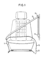
- Fig. 1 shows a front seat in a vehicle with a 3-point belt system.
- a belt retractor 10 and an upper deflection fitting 12 are on attached to a side wall of the vehicle.
- a webbing 16 runs from the belt retractor 10 to the upper deflection fitting 12, to a belt buckle 14 and is completed by an end fitting 18.
- a pyrotechnic linear tensioner drive 20 engages directly on the end fitting 18 on.
- the belt retractor 10, the belt buckle 14 and the end fitting 18 define three anchor points of the belt system.
- the Belt retractor 10 and the upper deflection fitting 12 are directly on the vehicle body attached, whereas the buckle 14 with the vehicle body is connected by an additional fitting.
- the tensioner drive 20 is a conventional one Trigger device activated. When the tensioner drive 20 is activated the end fitting 18 is pulled down, causing the webbing 16 train is exercised and webbing clearance is eliminated.
- Fig. 2 shows a rear seat group in a vehicle with three 3-point belt system. Parts of the back seat are shown cut out to the pyrotechnic, linear tensioner drive 20, the end fitting 18 and to show a lower deflection fitting 22 of a 3-point belt system, all belt systems are provided with similar arrangements.
- the pyrotechnic, linear tensioner drive 20 engages the end fitting 18 on, and the webbing 16 is between the buckle 14 or Insert tongue 14a and the end fitting 18 over the lower deflection fitting 22 out.
- the tensioner drive 20 and the lower deflection fitting 22 are located under the seat upholstery. In this way, the Tensioner drive 20 under the limited space in the area the rear seats. To obstruct the webbing 16 to be avoided by friction occurring on the deflection fitting 22, is the deflection surface with a friction-reducing surface structure Mistake.
- Fig. 3 shows an embodiment according to the invention, in which the end fitting 18 and a lower deflection fitting 22 side by side with one common bolts 24 are attached to the vehicle body.
- the Tensioner drive 20 engages via a pull rope 26 and a roller 28 on Webbing section 16a between deflection fitting 22 and end fitting 18 forming a webbing loop.
- the use of the pull rope 26 opens up numerous possibilities for the arrangement of the tensioner drive 20.
- By forming a loop 16a in the webbing necessary stroke of the belt tensioning system to a predetermined shortening to achieve the webbing halved.
- the tensioner drive 20 can thereby run shorter, making it easier to accommodate is.
- the deflection fitting 22 is provided with a deflection roller.
- the tensioner drive 20 also engages the belt strap by means of a Roll 28 on. Since the end fitting 18 and the lower deflection fitting 22 attached to the vehicle body with a common screw bolt 24 are not an additional attachment point on the vehicle body required.
Landscapes
- Engineering & Computer Science (AREA)
- Mechanical Engineering (AREA)
- Automotive Seat Belt Assembly (AREA)
- Devices For Conveying Motion By Means Of Endless Flexible Members (AREA)
Description
Die Erfindung betrifft ein Gurtstraffsystem für einen 3-Punkt-Gurt in Fahrzeugen, mit einem am Fahrzeugaufbau befestigten Gurtaufroller als erstem Verankerungspunkt, einem Gurtschloss als zweitem sowie einem Endbeschlag als drittem Verankerungspunkt und mit einem bei Aktivierung Zug ausübenden Strafferantrieb. Es ist im Stand der Technik bekannt, dass ein Gurtstraffsystem an den Gurtaufroller oder das Gurtschloss angreift. Das Gurtstraffsystem ist üblicherweise an der B-Säule des Fahrzeugs angeordnet oder, wenn er an das Gurtschloss angreift, neben dem Sitz am Boden des Fahrzeugs befestigt. Bei beengten Platzverhältnissen, z.B. an den Rücksitzen, können solche Anordnungen nach dem Stand der Technik schwierig unterzubringen sein.The invention relates to a belt tensioning system for a 3-point belt in Vehicles with a belt retractor attached to the vehicle body as first anchor point, a buckle as the second and one End fitting as a third anchor point and with one when activated Pulling tensioner drive. It is known in the art that a belt tensioning system on the belt retractor or the belt buckle attacks. The belt tensioning system is usually on the B-pillar the vehicle or if it engages the belt buckle, attached to the floor of the vehicle next to the seat. In confined spaces Space, e.g. at the rear seats, such arrangements can be difficult to accommodate according to the prior art.
Aus der EP-A-0 205 901 ist ein gattungsgemäßes Gurtstraffsystem für einem 3-Punkt-Gurt in Fahrzeugen bekannt, mit einem Gurtband, einem am Fahrzeugaufbau befestigten Gurtaufroller als erstem Verankerungspunkt, einem Gurtschloss als zweitem sowie einem Endbeschlag als drittem Verankerungspunkt und mit einem bei Aktivierung Zug ausübenden Strafferantrieb, wobei das Gurtband zwischen dem Gurtschloss und der Angriffstelle des Strafferantriebs über einen am Fahrzeugaufbau verankerten Umlenkbeschlag geführt ist. EP-A-0 205 901 is a generic belt tensioning system for a 3-point belt known in vehicles, with a belt, one on the vehicle body attached belt retractor as the first anchor point, a belt buckle as the second and a final fitting as the third anchor point and with a tensioner drive when the train is activated, the webbing between the buckle and the point of attack of the Tensioner drive via a deflection fitting anchored to the vehicle body is led.
Gegenüber bekannten Gurtstraffsystemen bietet die erfindungsgemäße Ausbildung verschiedene Unterbringungsmöglichkeiten auch bei beengten Platzverhältnissen im Fahrzeug, z.B. an den Rücksitzen.Compared to known belt tensioning systems, the invention offers Training different accommodation options even in confined spaces Space in the vehicle, e.g. in the back seats.
Erfindungsgemäß ist bei einem Gurtstraffsystem für einen 3-Punkt-Gurt in Fahrzeugen, wie er beispielsweise aus der genannten EP-A-0 205 901 bekannt ist, vorgesehen, dass der Strafferantrieb nahe dem Endbeschlag an dem zwischen Gurtschloss und Endbeschlag gelegenen Gurtabschnitt unter Bildung einer Gurtschlaufe angreift. Dadurch wird der erforderliche Strafferhub halbiert, so dass die Baulänge des Strafferantriebs, der beispielsweise auf der Rückseite des Rücksitzes, auf der Türschwelle oder unter der Sitzpolsterung angeordnet sein kann, reduziert werden kann.According to the invention in a belt tensioning system for a 3-point belt in vehicles such as that described in EP-A-0 205 901 is known, provided that the tensioner drive near the end fitting on the belt section between the buckle and the end fitting attacks, forming a belt loop. This will make the required Penalty length halved so that the overall length of the penalty drive, for example on the back of the back seat, on the doorstep or can be arranged under the seat upholstery, reduced can be.
Eine Ausführungsform, bei der der Strafferantrieb über ein Zugseil an dem zwischen Gurtschloss und Endbeschlag gelegenen Gurtabschnitt angeschlossen ist, ist insbesondere dann vorteilhaft, wenn nicht genügend Platz vorhanden ist, um den Strafferantrieb direkt angrenzend an den Endbeschlag anzuordnen.An embodiment in which the tensioner drive via a pull rope connected to the belt section between the buckle and the end fitting is particularly advantageous if not sufficient Space is available to drive directly adjacent to the tensioner Arrange end fitting.
Unter beengten Platzverhältnissen besonders vorteilhaft ist eine Ausführungsform, bei der der Umlenkbeschlag und der Endbeschlag nebeneinander angeordnet sind und insbesondere mittels eines gemeinsamen Schraubbolzens am Fahrzeugaufbau verankert sind.An embodiment is particularly advantageous where space is limited. where the deflection fitting and the end fitting side by side are arranged and in particular by means of a common Bolt are anchored to the vehicle body.
Zur Verringerung der an dem Umlenkbeschlag auftretenden Reibung, ist dieser vorteilhafterweise mit einer drehbaren Umlenkrolle versehen, oder die Umlenkfläche ist mit einer reibungsmindernden Oberflächenstruktur versehen.To reduce the friction occurring on the deflection fitting this advantageously provided with a rotatable deflection roller, or the deflection surface is with a friction-reducing surface structure Mistake.
Vorteilhafterweise ist der Strafferantrieb durch einen pyrotechnischen Linearantrieb gebildet.The tensioner drive is advantageously driven by a pyrotechnic Linear drive formed.
In den beigefügten Zeichnungen zeigen:
Die im folgenden beschriebenen Figuren 1 und 2 zeigen keine Ausführungsbeispiele der Erfindung, sondern lediglich Darstellungen, die das Verständnis der Erfindung erleichtern.Figures 1 and 2 described below do not show any exemplary embodiments the invention, but only representations that the Facilitate understanding of the invention.
Fig. 1 zeigt einen Vordersitz in einem Fahrzeug mit 3-Punkt-Gurtsystem.
Ein Gurtaufroller 10 und ein oberer Umlenkbeschlag 12 sind an
einer Seitenwand des Fahrzeugs befestigt. Ein Gurtband 16 läuft von
dem Gurtaufroller 10 zu dem oberen Umlenkbeschlag 12, zu einem Gurtschloss
14 und ist durch einen Endbeschlag 18 abgeschlossen. Ein pyrotechnischer
linearer Strafferantrieb 20 greift direkt an den Endbeschlag
18 an. Der Gurtaufroller 10, das Gurtschloss 14 und der Endbeschlag
18 legen drei Verankerungspunkte des Gurtsystems fest. Der
Gurtaufroller 10 und der obere Umlenkbeschlag 12 sind direkt am Fahrzeugaufbau
befestigt, wohingegen das Gurtschloss 14 mit dem Fahrzeugaufbau
durch einen zusätzlichen Beschlag verbunden ist. Bei dem in
Fig. 1 gezeigten Gurtstraffsystem greift ein Ende des Strafferantriebs
20 an den Endbeschlag 18 an, und das andere Ende ist an dem Fahrzeugaufbau
befestigt. Der Strafferantrieb 20 wird durch eine herkömmliche
Auslösevorrichtung aktiviert. Bei Aktivierung des Strafferantriebs 20
wird der Endbeschlag 18 nach unten gezogen, wodurch auf das Gurtband
16 Zug ausgeübt wird und Gurtbandspiel beseitigt wird.Fig. 1 shows a front seat in a vehicle with a 3-point belt system.
A
Fig. 2 zeigt eine Rücksitzgruppe in einem Fahrzeug mit drei 3-Punkt-Gurtsystem.
Teile des Rücksitzes sind ausgeschnitten dargestellt, um
den pyrotechnischen, linearen Strafferantrieb 20, den Endbeschlag 18
und einen unteren Umlenkbeschlag 22 eines 3-Punkt-Gurtsystems zu zeigen,
wobei alle Gurtsysteme mit ähnlichen Anordnungen versehen sind.
Der pyrotechnische, lineare Strafferantrieb 20 greift an den Endbeschlag
18 an, und das Gurtband 16 ist zwischen dem Gurtschloss 14 bzw.
Steckzunge 14a und dem Endbeschlag 18 über den unteren Umlenkbeschlag
22 geführt. Der Strafferantrieb 20 und der untere Umlenkbeschlag 22
sind unter der Sitzpolsterung angeordnet. Auf diese Weise kann der
Strafferantrieb 20 unter den beengten Platzverhältnissen im Bereich
der Rücksitze untergebracht werden. Um eine Behinderung des Gurtbandes
16 durch an dem Umlenkbeschlag 22 auftretende Reibung zu vermeiden,
ist die Umlenkfläche mit einer reibungsmindernden Oberflächenstruktur
versehen.Fig. 2 shows a rear seat group in a vehicle with three 3-point belt system.
Parts of the back seat are shown cut out to
the pyrotechnic,
Fig. 3 zeigt eine erfindungsgemäße Ausführungsform, bei der der Endbeschlag
18 und ein unterer Umlenkbeschlag 22 nebeneinander mit einem
gemeinsamen Schraubbolzen 24 am Fahrzeugaufbau befestigt sind. Der
Strafferantrieb 20 greift über ein Zugseil 26 und eine Rolle 28 am
Gurtbandabschnitt 16a zwischen Umlenkbeschlag 22 und Endbeschlag 18
unter Bildung einer Gurtbandschlaufe an. Die Verwendung des Zugseils
26 eröffnet zahlreiche Möglichkeiten für die Anordnung des Strafferantrieb
20. Durch Bilden einer Schlaufe 16a in dem Gurtband wird der
notwendige Hub des Gurtstraffsystems, um eine vorbestimmte Verkürzung
des Gurtbandes zu erzielen, halbiert. Der Strafferantrieb 20 kann dadurch
kürzer ausgeführt werden, wodurch seine Unterbringung erleichtert
ist. Um die Reibung zwischen dem Gurtband und dem Umlenkbeschlag
22 zu vermindern, ist der Umlenkbeschlag 22 mit einer Umlenkrolle versehen.
Auch der Strafferantrieb 20 greift an dem Gurtband mittels einer
Rolle 28 an. Da der Endbeschlag 18 und der untere Umlenkbeschlag
22 an dem Fahrzeugaufbau mit einem gemeinsamen Schraubbolzen 24 befestigt
sind, ist kein zusätzlicher Befestigungspunkt an dem Fahrzeugaufbau
erforderlich.Fig. 3 shows an embodiment according to the invention, in which the end fitting
18 and a lower deflection fitting 22 side by side with one
Claims (5)
- A belt tensioning system for a 3-point vehicular seat belt, comprising a belt webbing (16), a belt retractor (10) as a first anchoring point being fixed to the vehicle body, a belt buckle (14) as a second anchoring point and an end fitting (18) as a third anchoring point, and a tensioner drive (20) exerting a tensile force when activated, the belt webbing (16) being guided between the belt buckle (14) and the point of engagement of the tensioner drive (20) via a deflector fitting (22) anchored to the vehicle body, characterized in that the tensioner drive (20) engages the belt section (16a) located between the deflector fitting (22) and the end fitting (18) close to the end fitting (18), thereby forming a belt loop.
- The belt tensioning system as set forth in claim 1, characterized in that the tensioner drive (20) is connected via a traction cable (26) to the belt section (16a) located between the belt buckle (14) and the end fitting (18).
- The belt tensioning system as set forth in claim 1 or 2, characterized in that the deflector fitting (22) and the end fitting (18) are arranged side by side and in particular are anchored to the vehicle body by means of a common through-bolt (24).
- The belt tensioning system as set forth in any of the claims 1 to 3, characterized in that the deflector fitting (22) is provided for low-friction operation, particularly by employing a rotatable deflection sheave or an anti-friction surface structure on the deflecting surface.
- The belt tensioning system as set forth in any of the preceding claims, characterized in that the tensioner drive (20) is formed by a pyrotechnical linear drive.
Applications Claiming Priority (2)
| Application Number | Priority Date | Filing Date | Title |
|---|---|---|---|
| DE29606896U DE29606896U1 (en) | 1996-04-16 | 1996-04-16 | Belt tensioners |
| DE29606896U | 1996-04-16 |
Publications (2)
| Publication Number | Publication Date |
|---|---|
| EP0802096A1 EP0802096A1 (en) | 1997-10-22 |
| EP0802096B1 true EP0802096B1 (en) | 2001-07-25 |
Family
ID=8022657
Family Applications (1)
| Application Number | Title | Priority Date | Filing Date |
|---|---|---|---|
| EP97104855A Revoked EP0802096B1 (en) | 1996-04-16 | 1997-03-21 | Belt pretensionner |
Country Status (7)
| Country | Link |
|---|---|
| US (1) | US5845939A (en) |
| EP (1) | EP0802096B1 (en) |
| JP (1) | JP2916439B2 (en) |
| KR (1) | KR100254853B1 (en) |
| CZ (1) | CZ285950B6 (en) |
| DE (2) | DE29606896U1 (en) |
| ES (1) | ES2109211T3 (en) |
Cited By (3)
| Publication number | Priority date | Publication date | Assignee | Title |
|---|---|---|---|---|
| US12179691B1 (en) | 2023-09-25 | 2024-12-31 | Ford Global Technologies, Llc | Pyrotechnically activated hook for seatbelt assembly |
| US12358450B2 (en) | 2023-09-25 | 2025-07-15 | Ford Global Technologies, Llc | Rotatable seatbelt buckle |
| US12384323B2 (en) | 2023-09-25 | 2025-08-12 | Ford Global Technologies, Llc | Rotatable seatbelt buckle |
Families Citing this family (16)
| Publication number | Priority date | Publication date | Assignee | Title |
|---|---|---|---|---|
| DE29710325U1 (en) * | 1997-06-12 | 1998-10-15 | Trw Occupant Restraint Systems Gmbh, 73551 Alfdorf | Belt tensioners for an occupant restraint system |
| US6238003B1 (en) * | 1998-10-13 | 2001-05-29 | Breed Automotive Technology, Inc. | Outboard sill pretensioner |
| JP4242520B2 (en) * | 1999-01-21 | 2009-03-25 | オートリブ株式会社 | Seat belt device |
| DE10105500B4 (en) * | 2001-02-07 | 2004-02-05 | Breed Automotive Technology, Inc., Lakeland | Device for tightening a three-point seat belt arranged in a vehicle rear |
| DE10112853A1 (en) * | 2001-03-16 | 2002-10-02 | Breed Automotive Tech | Three-point seat belt system for a motor vehicle front seat |
| DE10141297A1 (en) * | 2001-08-23 | 2003-03-13 | Breed Automotive Tech | Vehicle seat belt with a final fitting tensioner |
| DE10209235B4 (en) | 2002-03-04 | 2006-09-14 | Daimlerchrysler Ag | Safety device for a comfort seat |
| JP2004090667A (en) * | 2002-08-29 | 2004-03-25 | Takata Corp | Seat belt device |
| JP4193580B2 (en) * | 2003-05-21 | 2008-12-10 | トヨタ自動車株式会社 | Seat belt |
| DE102005019439B3 (en) * | 2005-04-25 | 2006-10-19 | Autoliv Development Ab | Safety belt system for a vehicle comprises a belt with a lower end joined to a vehicle using connecting devices |
| JP5473322B2 (en) * | 2008-12-29 | 2014-04-16 | テイ・エス テック株式会社 | Vehicle seat |
| EP2752332A4 (en) * | 2011-08-29 | 2015-04-01 | Toyota Motor Co Ltd | SEAT STRUCTURE FOR VEHICLE |
| DE102012023778A1 (en) * | 2012-12-05 | 2014-06-05 | GM Global Technology Operations LLC (n. d. Ges. d. Staates Delaware) | Seat belt webbing for placement on a vehicle seat of a motor vehicle |
| JP2015040018A (en) * | 2013-08-23 | 2015-03-02 | トヨタ自動車株式会社 | Rear seat cushion structure for vehicles |
| DE102014201231A1 (en) * | 2014-01-23 | 2015-07-23 | Volkswagen Aktiengesellschaft | Belt tensioner for a vehicle seat belt assembly |
| KR102585755B1 (en) * | 2018-10-12 | 2023-10-10 | 현대자동차주식회사 | Seat belt safety apparatus for vehicle |
Family Cites Families (5)
| Publication number | Priority date | Publication date | Assignee | Title |
|---|---|---|---|---|
| JPS49125430U (en) * | 1973-02-26 | 1974-10-26 | ||
| SE381814B (en) * | 1974-10-03 | 1975-12-22 | Foerenade Fabriksverken | DEVICE FOR STRETCHING A BAND INCLUDING IN A VEHICLE |
| JPS61155039A (en) * | 1984-12-27 | 1986-07-14 | Nissan Motor Co Ltd | Sheet belt device |
| DE3665554D1 (en) * | 1985-05-21 | 1989-10-19 | Autoflug Gmbh | Safety belt arrangement, especially for motor vehicles |
| DE3532407A1 (en) * | 1985-09-11 | 1987-03-12 | Autoflug Gmbh | SEAT-INTEGRATED SAFETY BELT SYSTEM |
-
1996
- 1996-04-16 DE DE29606896U patent/DE29606896U1/en not_active Expired - Lifetime
-
1997
- 1997-03-21 DE DE59704101T patent/DE59704101D1/en not_active Revoked
- 1997-03-21 EP EP97104855A patent/EP0802096B1/en not_active Revoked
- 1997-03-21 ES ES97104855T patent/ES2109211T3/en not_active Expired - Lifetime
- 1997-04-11 KR KR1019970013357A patent/KR100254853B1/en not_active Expired - Fee Related
- 1997-04-14 US US08/824,710 patent/US5845939A/en not_active Expired - Fee Related
- 1997-04-15 JP JP9097001A patent/JP2916439B2/en not_active Expired - Lifetime
- 1997-04-16 CZ CZ971150A patent/CZ285950B6/en not_active IP Right Cessation
Cited By (3)
| Publication number | Priority date | Publication date | Assignee | Title |
|---|---|---|---|---|
| US12179691B1 (en) | 2023-09-25 | 2024-12-31 | Ford Global Technologies, Llc | Pyrotechnically activated hook for seatbelt assembly |
| US12358450B2 (en) | 2023-09-25 | 2025-07-15 | Ford Global Technologies, Llc | Rotatable seatbelt buckle |
| US12384323B2 (en) | 2023-09-25 | 2025-08-12 | Ford Global Technologies, Llc | Rotatable seatbelt buckle |
Also Published As
| Publication number | Publication date |
|---|---|
| ES2109211T1 (en) | 1998-01-16 |
| ES2109211T3 (en) | 2001-11-16 |
| CZ115097A3 (en) | 1999-09-15 |
| KR100254853B1 (en) | 2000-08-01 |
| KR970069664A (en) | 1997-11-07 |
| JPH1035414A (en) | 1998-02-10 |
| DE59704101D1 (en) | 2001-08-30 |
| US5845939A (en) | 1998-12-08 |
| CZ285950B6 (en) | 1999-12-15 |
| DE29606896U1 (en) | 1996-08-08 |
| EP0802096A1 (en) | 1997-10-22 |
| JP2916439B2 (en) | 1999-07-05 |
Similar Documents
| Publication | Publication Date | Title |
|---|---|---|
| EP0802096B1 (en) | Belt pretensionner | |
| DE69402817T3 (en) | Retractor for a buckle | |
| DE10105500B4 (en) | Device for tightening a three-point seat belt arranged in a vehicle rear | |
| DE10251040B4 (en) | Child seat | |
| EP0499856B1 (en) | Belt fastener arrangement for a safety belt system | |
| DE10302713A1 (en) | Four-point safety restraint system | |
| EP1369318B1 (en) | Device for tensioning a seat belt | |
| EP0205901A2 (en) | Safety belt arrangement, especially for motor vehicles | |
| DE102008026410A1 (en) | Safety belt system for restraining passenger sitting on seat of vehicle, comprises safety-belt retractor for winding end of safety belt, and another safety-belt retractor is provided for winding end of another safety belt | |
| DE69628941T2 (en) | BELT ARRANGEMENT | |
| DE102008029351A1 (en) | Safety belt system for motor vehicle seat in motor vehicle, has belt retractor and seat-belt tensioner, where belt retractor and seat-belt tensioner are arranged in backrest of motor vehicle seat | |
| DE3400115A1 (en) | Seat belt system | |
| DE3734152C2 (en) | Belt tightening of a lap belt end point via a pulling rope | |
| DE2635588A1 (en) | SEAT BELT ATTACHED TO A VEHICLE DOOR | |
| DE102004023394B4 (en) | Locking tongue for a safety belt system | |
| DE4027906A1 (en) | SHOULDER STRAP ADJUSTMENT OF A SEAT BELT | |
| DE60207023T2 (en) | Safety belt system for a motor vehicle | |
| DE69801137T2 (en) | Anchoring device for the seat belt of the rear seats of a motor vehicle | |
| DE2948121C2 (en) | Restraint system for the occupant of a motor vehicle | |
| DE2360702A1 (en) | Motor car safety belt system - has shoulder belt threaded through eyelet of metal fitting pivoted to middle column of bodywork | |
| DE102007033154B4 (en) | Safety belt system for a motor vehicle | |
| EP1270345B1 (en) | Safety belt system | |
| DE3209351A1 (en) | Vehicle with a seat which is guided in a longitudinal guide and with a safety belt attached to the seat | |
| DE3731697A1 (en) | Safety belt system | |
| DE102011117745A1 (en) | Safety belt arrangement for vehicle seat, comprises safety belt, which has primary end connected with end fitting that is attached to vehicle body, where secondary end is provided, which is attached to strap rewinder |
Legal Events
| Date | Code | Title | Description |
|---|---|---|---|
| PUAI | Public reference made under article 153(3) epc to a published international application that has entered the european phase |
Free format text: ORIGINAL CODE: 0009012 |
|
| AK | Designated contracting states |
Kind code of ref document: A1 Designated state(s): DE ES FR GB IT SE |
|
| ITCL | It: translation for ep claims filed |
Representative=s name: DR. ING. A. RACHELI & C. |
|
| GBC | Gb: translation of claims filed (gb section 78(7)/1977) | ||
| REG | Reference to a national code |
Ref country code: ES Ref legal event code: BA2A Ref document number: 2109211 Country of ref document: ES Kind code of ref document: T1 |
|
| EL | Fr: translation of claims filed | ||
| 17P | Request for examination filed |
Effective date: 19971222 |
|
| RAP1 | Party data changed (applicant data changed or rights of an application transferred) |
Owner name: TRW OCCUPANT RESTRAINT SYSTEMS GMBH & CO. KG |
|
| 17Q | First examination report despatched |
Effective date: 19990518 |
|
| GRAG | Despatch of communication of intention to grant |
Free format text: ORIGINAL CODE: EPIDOS AGRA |
|
| GRAG | Despatch of communication of intention to grant |
Free format text: ORIGINAL CODE: EPIDOS AGRA |
|
| GRAH | Despatch of communication of intention to grant a patent |
Free format text: ORIGINAL CODE: EPIDOS IGRA |
|
| GRAH | Despatch of communication of intention to grant a patent |
Free format text: ORIGINAL CODE: EPIDOS IGRA |
|
| GRAA | (expected) grant |
Free format text: ORIGINAL CODE: 0009210 |
|
| AK | Designated contracting states |
Kind code of ref document: B1 Designated state(s): DE ES FR GB IT SE |
|
| REF | Corresponds to: |
Ref document number: 59704101 Country of ref document: DE Date of ref document: 20010830 |
|
| ITF | It: translation for a ep patent filed | ||
| GBT | Gb: translation of ep patent filed (gb section 77(6)(a)/1977) |
Effective date: 20010919 |
|
| ET | Fr: translation filed | ||
| REG | Reference to a national code |
Ref country code: ES Ref legal event code: FG2A Ref document number: 2109211 Country of ref document: ES Kind code of ref document: T3 |
|
| REG | Reference to a national code |
Ref country code: GB Ref legal event code: IF02 |
|
| PGFP | Annual fee paid to national office [announced via postgrant information from national office to epo] |
Ref country code: FR Payment date: 20020228 Year of fee payment: 6 |
|
| PGFP | Annual fee paid to national office [announced via postgrant information from national office to epo] |
Ref country code: ES Payment date: 20020315 Year of fee payment: 6 |
|
| PLBQ | Unpublished change to opponent data |
Free format text: ORIGINAL CODE: EPIDOS OPPO |
|
| PG25 | Lapsed in a contracting state [announced via postgrant information from national office to epo] |
Ref country code: GB Free format text: LAPSE BECAUSE OF NON-PAYMENT OF DUE FEES Effective date: 20020321 |
|
| PG25 | Lapsed in a contracting state [announced via postgrant information from national office to epo] |
Ref country code: SE Free format text: LAPSE BECAUSE OF NON-PAYMENT OF DUE FEES Effective date: 20020322 |
|
| PLBI | Opposition filed |
Free format text: ORIGINAL CODE: 0009260 |
|
| PGFP | Annual fee paid to national office [announced via postgrant information from national office to epo] |
Ref country code: DE Payment date: 20020327 Year of fee payment: 6 |
|
| 26 | Opposition filed |
Opponent name: BREED AUTOMOTIVE TECHNOLOGY, INC. 5300 ALLEN K. BR Effective date: 20020315 |
|
| PLBF | Reply of patent proprietor to notice(s) of opposition |
Free format text: ORIGINAL CODE: EPIDOS OBSO |
|
| PLBF | Reply of patent proprietor to notice(s) of opposition |
Free format text: ORIGINAL CODE: EPIDOS OBSO |
|
| EUG | Se: european patent has lapsed |
Ref document number: 97104855.8 |
|
| RDAH | Patent revoked |
Free format text: ORIGINAL CODE: EPIDOS REVO |
|
| GBPC | Gb: european patent ceased through non-payment of renewal fee |
Effective date: 20020321 |
|
| RDAG | Patent revoked |
Free format text: ORIGINAL CODE: 0009271 |
|
| STAA | Information on the status of an ep patent application or granted ep patent |
Free format text: STATUS: PATENT REVOKED |
|
| 27W | Patent revoked |
Effective date: 20021108 |