EP0802022B1 - Clamping device with a mechanical power booster - Google Patents
Clamping device with a mechanical power booster Download PDFInfo
- Publication number
- EP0802022B1 EP0802022B1 EP97103816A EP97103816A EP0802022B1 EP 0802022 B1 EP0802022 B1 EP 0802022B1 EP 97103816 A EP97103816 A EP 97103816A EP 97103816 A EP97103816 A EP 97103816A EP 0802022 B1 EP0802022 B1 EP 0802022B1
- Authority
- EP
- European Patent Office
- Prior art keywords
- housing
- clamping
- clamping member
- clamping device
- tendon
- Prior art date
- Legal status (The legal status is an assumption and is not a legal conclusion. Google has not performed a legal analysis and makes no representation as to the accuracy of the status listed.)
- Expired - Lifetime
Links
Images

Classifications
-
- B—PERFORMING OPERATIONS; TRANSPORTING
- B25—HAND TOOLS; PORTABLE POWER-DRIVEN TOOLS; MANIPULATORS
- B25B—TOOLS OR BENCH DEVICES NOT OTHERWISE PROVIDED FOR, FOR FASTENING, CONNECTING, DISENGAGING OR HOLDING
- B25B1/00—Vices
-
- B—PERFORMING OPERATIONS; TRANSPORTING
- B25—HAND TOOLS; PORTABLE POWER-DRIVEN TOOLS; MANIPULATORS
- B25B—TOOLS OR BENCH DEVICES NOT OTHERWISE PROVIDED FOR, FOR FASTENING, CONNECTING, DISENGAGING OR HOLDING
- B25B1/00—Vices
- B25B1/06—Arrangements for positively actuating jaws
- B25B1/10—Arrangements for positively actuating jaws using screws
- B25B1/106—Arrangements for positively actuating jaws using screws with mechanical or hydraulic power amplifiers
-
- F—MECHANICAL ENGINEERING; LIGHTING; HEATING; WEAPONS; BLASTING
- F16—ENGINEERING ELEMENTS AND UNITS; GENERAL MEASURES FOR PRODUCING AND MAINTAINING EFFECTIVE FUNCTIONING OF MACHINES OR INSTALLATIONS; THERMAL INSULATION IN GENERAL
- F16H—GEARING
- F16H25/00—Gearings comprising primarily only cams, cam-followers and screw-and-nut mechanisms
- F16H25/18—Gearings comprising primarily only cams, cam-followers and screw-and-nut mechanisms for conveying or interconverting oscillating or reciprocating motions
Definitions
- the invention relates to a clamping device with mechanical Power amplifier, with a threaded spindle, which in particular on a movable cocking slide Machine vise or the like. Acts and in one stationary nut of the same can be screwed, with a enclosing the power amplifier, coaxial to the threaded spindle arranged and connected to this in a rotationally fixed manner, essentially cylindrical housing, with one in the Housing axially displaceable and non-rotatably connected to it, first tendon, one end of which on a Clamping slide acts on the pressure element with a rotatably arranged in the housing, second tendon, with several between the tendons arranged clamping bolts in an end position (Relaxation position) of the second tendon in pointed Angle to a through the housing axis Plane inclined and in the other end position (clamping position) of the second tendon approximately parallel to this Are arranged with one of the two tendons on top of each other spring arrangement to be moved, with one the second tendon axially
- the second tendon is directly connected connected to the drive shaft.
- a hand crank can be attached.
- the screw spindle is designed as a hollow spindle in which a push rod is displaceable, which forms the pressure element.
- the push rod lies on the one hand on the first tendon and on the other hand on the cocking slide near it Jaws on.
- This slidable jaws forms part of a machine vise.
- the two tendons are located on one workpiece in the relaxed position, the tensioning bolts in pointed Angle to a through the housing axis Plane are inclined. Through strong disc springs that act on the first tendon, they are in this held oblique position. As a result of the spring force when turning the hand crank the second one Do not twist the tendon relative to the first tendon.
- the first tendon moves the push rod and this in turn the cocking slide.
- the means of Clamping bolts achieved high translation becomes a significant one Clamping pressure exerted on the cocking slide.
- This by axially displacing the first tendon or the push rod caused displacement of the cocking slide under high pressure is called the clamping stroke.
- the disc springs must be very strong be designed, because otherwise the clamping device already with very low clamping force from the infeed stroke to the Toggles clamping stroke, so that then because of the proportion small clamping stroke is no longer sufficient Tension is achievable. Large and strong disc springs also require additional ones in the axial direction Overall length.
- the invention is therefore based on the object Clamping device with power amplifier of the aforementioned To create a way to rotate the Hand crank required torque also for the clamping stroke is as small as possible to make it simple and convenient To enable manual operation.
- the invention is therefore based on the idea between the second tendon and the drive shaft a planetary gear to order through the reduction ratio of this planetary gear the one to be used on the hand crank Decrease hand strength.
- a planetary gear with a reduction ratio of 4 - 5: 1 requires only one in the axial direction of the housing small space requirement of about 10 mm. This space requirement can be compensated for by the fact that in the inventive Clamping device which spring arrangement the tendons moved towards each other, much smaller can be trained and therefore also elsewhere can be accommodated than in the known clamping device.
- the planetary gear requires in the invention Clamping device also takes up little space because of the Web of the planetary gear through the second tendon is formed and this is therefore a multiple function having.
- the tensioning device according to the invention the spring-loaded between the housing and the second tendon Locking clutch on.
- the second tendon and thus the web of the planetary gear is coupled to the housing, so that when the hand crank rotates, the drive shaft rotates together with the housing and the screw spindle.
- the cocking slide is countered in a feed stroke the workpiece moves and with a predetermined preload pressed the workpiece.
- the machine vice shown in the drawing has a base plate 1 with a fixed jaw 2 on.
- a cocking slide 3 in Slidably mounted towards S, which is the movable one Clamping jaw 4 carries.
- a nut 5 is arranged, which has a cross bolt 6 compared to the main body in different places is definable. That is why the mother 5 is considered stationary Referred to mother.
- the clamping device 7 is in one Longitudinal bore 8 of the cocking slide 3 rotatably mounted. Their constructive structure is shown in FIGS. 2 and 3 shown in more detail.
- the clamping device 7 has a threaded spindle 9, those in the stationary nut 5 of the machine vice is screwable. Coaxial to the threaded spindle 9 an essentially cylindrical housing 10 is provided, this housing 10 encloses one further below power amplifier described in more detail and instructs its front end facing the screw spindle a coaxial cylindrical, hollow extension 11. The diameter of this approach 11 is smaller than that of the housing 10. With this approach 11, the housing 10 in the longitudinal bore 8 of the cocking slide 3 rotatably mounted.
- the threaded spindle 9 has at one end 9a a finer thread 12 with which they firmly in the Approach 11 is screwed in. This is the threaded spindle 9 rotatably connected to the housing 10.
- the power amplifier enclosed by the housing 10 exists essentially from a first tendon 13, a second tendon 14, two arranged between them Clamping bolts 15 and four balls 16.
- the clamping bolts 15 have a ball socket at both ends, in which the ball 16 engages.
- the two tendons 13 and 14 have hemispherical depressions provided, in which the balls 16 engage. Possibly can also use the clamping bolts 15 at their ends be designed hemispherical, in which case the balls 16 omitted.
- the clamping device is in its initial position, i.e. shown in relaxation position.
- the second tendon 14 by about 52 ° opposite twisted the first tendon 13.
- the clamping bolts 15 are consequently entangled or at an acute angle arranged inclined to the housing axis A. Only the For the sake of clarity, the clamping bolts are shown in FIG 15 in a position parallel to the housing axis A. shown, which they occupy in the clamping position.
- the first tendon 13 is axially displaceable in the housing 10, however, rotatably mounted relative to the housing 10.
- a pressure ring 17 is axially displaceable.
- This pressure ring 17 is on the one hand on an annular surface 18 of the cocking slide 3 and on the other hand on several Push pin 19 in the axial bores 20 of the housing 10 are movable.
- One of these Push pin 20 can be formed approximately longer and engage in a recess 21 of the tendon 13, whereby the latter is rotationally fixed relative to the housing 10.
- a compression spring 22 which is attached to the end 9a of the screw 9 is supported. The compression spring 22 acts on the first tendon 13 and exercises with this on towards the second Tendon 14 aligned pressure.
- the second tendon 14 is limited in the housing 10 rotatably mounted.
- the housing known clamping force adjusting device 23 there is one at the rear end 10b of the housing known clamping force adjusting device 23 (see e.g. DE 37 29 093 C1) arranged.
- This consists of an in the end plate 24 of the housing screwed set screw 25, several strong disc springs 26 and an abutment disc 27.
- the set screw 25 By turning the set screw 25 can in the relaxed position of the device Distance between the front end 25a of the set screw 25 and the rear end 27a of the abutment disc 27 and thus the maximum clamping force of the clamping device can be set. The larger the original distance is, the smaller the achievable clamping force.
- the two surfaces 25a and 27a the device is at its maximum Tension adjusted.
- a drive shaft 28 can be rotated in the adjusting screw 25, a crank handle 29 can be attached to the outer end 28a thereof is.
- a planetary gear 30 interposed between this drive shaft 28 and the second tendon 14 .
- the sun gear 31 of this planetary gear is by a corresponding toothing on formed front end of the drive shaft 28.
- the ring gear 32 is connected to the housing 10 or forms it advantageously part of the housing 10.
- Das second tendon 14 forms the bridge of the planetary gear 30.
- there are several trunnions 33, for the rotatable mounting of the planet gears 34 serve in corresponding recesses 35 of the second Tendon 14 used.
- the journal 33 are on the sides facing away from the second tendon 14 of the planet gears slightly and are supported a thrust washer 36a. Between this thrust washer 36a and the abutment disc 27 is an axial bearing 36 arranged.
- the tensioning device is completed by a Locking clutch 38, which between the housing 10 and the second tendon 14 is effective.
- This locking clutch 38 has several offset in the circumferential direction of the housing mutually arranged latching elements 39, the radially movable recesses 40 are radially movable and by the force of the leaf springs 41 are loaded radially inwards.
- the locking elements 39 grip with their inner, prism-shaped Ends 39a in corresponding prism-shaped grooves 42 on Scope of the second tendon 14.
- the locking elements can also be designed as balls, which by means of coil springs in corresponding frustoconical Depressions on the circumference of the second tendon 14 intervene.
- the pressure ring 17 is expedient by O-rings 43, 44 sealed against the housing 10 and the neck 11.
- the others are also expedient the housing 10 movable and out of this Parts such as the set screw 25 and the Drive spindle 28, sealed by O-rings 46, 47.
- This also makes it possible to completely enclose the housing 10 fill with oil. This oil doesn't just act as Lubricant for all in the housing 10 Parts, but the oil also prevents penetration of coolant and chips in the housing.
- the mode of action is as follows:
- the drive shaft can be rotated. Because first the second tendon 14 by means of the locking coupling 38 is coupled to the housing 10 in a rotationally fixed manner the planetary gear 30 blocked.
- the housing 10 in relation Turned 1: 1 and thus also with the approach 11 non-rotatably connected screw spindle 9.
- the screw spindle 9 is screwed into the nut 5, the Screw spindle 9 when clamping according to Figure 1 to the left shifts.
- the pressure ring 17 lies on the ring surface 18 of the cocking slide 3 and pushes it also to the left until its jaw 4 on the workpiece is present.
- the journals 33 are rotated in the circumferential direction and also rotate the second tendon 14 compared to the first held by the housing 10 Tendon 13.
- the clamping bolt 15th erect, i.e. their entanglement or their pointed
- the angle with respect to the housing axis A decreases.
- the clamping bolt 15 increases the distance between the two tendons 13, 14. Since the second tendon 14 via the journal 33, the thrust washer 35, the thrust bearing 36, the thrust washer 37 and the adjusting screw 25 in the axial direction is supported against the housing 10 and not after can dodge to the right, the first tendon 13th moved to the left in the housing 10.
- the first tendon 13 presses on the pressure ring 19 on the pressure ring 17 and this presses the cocking slide with a high one Push left against the workpiece W. This is called Called clamping stroke.
- the crank handle 29 during the clamping stroke by about 330 ° until the axes of the clamping bolts 15 parallel to the housing axis A run.
- the rotation of the crank handle 29 and thus the However, rotation of the second tendon 14 is still continued until the axes of the clamping bolts 15 via their dead center position running parallel to the housing axis A. about 3 ° opposite to their starting position are inclined with respect to the housing axis A.
- the tensioning device is released by turning it backwards the crank handle 29 Planetary gear 30 first the second tendon 14th in the opposite direction to the first Tensioning element 13 rotates until the tensioning bolts 14 again their position in relation to the housing axis A. have taken and the locking elements 39 of the locking clutch 38 are snapped into their recesses 42. Before the locking elements 39 again in their locking recesses 42 snap, they lie on the circumference of the second Tendon 14 and are against by the springs 41 pressed the perimeter, causing between these and the Latching elements 39 sliding friction arises. This will at the initial reverse rotation of the hand crank the second tendon 14 braked and a snap back the crank handle 29 prevents if you do not properly holds or lets go.
Abstract
Description
Die Erfindung betrifft eine Spannvorrichtung mit mechanischem Kraftverstärker, mit einer Gewindespindel, die insbesondere auf einem beweglichen Spannschieber eines Maschinenschraubstockes oder dgl. einwirkt und in einer stationären Mutter desselben verschraubbar ist, mit einem den Kraftverstärker umschließenden, koaxial zur Gewindespindel angeordneten und mit dieser drehfest verbundenen, im wesentlichen zylindrischen Gehäuse, mit einem in dem Gehäuse axial verschiebbaren und drehfest mit diesem verbundenen, ersten Spannglied, dessen eines Ende auf ein am Spannschieber anliegendes Druckelement einwirkt, mit einem in dem Gehäuse begrenzt drehbar angeordneten, zweiten Spannglied, mit mehreren zwischen den Spanngliedern angeordneten Spannbolzen, die in einer Endlage (Entspannstellung) des zweiten Spanngliedes in spitzem Winkel zu einer durch die Gehäuseachse verlaufenden Ebene geneigt und in der anderen Endlage (Spannstellung) des zweiten Spanngliedes annähernd parallel zu dieser Ebene angeordnet sind, mit einer beide Spannglieder aufeinander zu bewegenden Federanordnung, mit einem das zweite Spannglied gegenüber dem Gehäuse axial abstützenden Axiallager und mit einer auf das zweite Spannglied einwirkenden, koaxial zum Gehäuse angeordneten Antriebswelle.The invention relates to a clamping device with mechanical Power amplifier, with a threaded spindle, which in particular on a movable cocking slide Machine vise or the like. Acts and in one stationary nut of the same can be screwed, with a enclosing the power amplifier, coaxial to the threaded spindle arranged and connected to this in a rotationally fixed manner, essentially cylindrical housing, with one in the Housing axially displaceable and non-rotatably connected to it, first tendon, one end of which on a Clamping slide acts on the pressure element with a rotatably arranged in the housing, second tendon, with several between the tendons arranged clamping bolts in an end position (Relaxation position) of the second tendon in pointed Angle to a through the housing axis Plane inclined and in the other end position (clamping position) of the second tendon approximately parallel to this Are arranged with one of the two tendons on top of each other spring arrangement to be moved, with one the second tendon axially relative to the housing supporting axial bearing and with one on the second Tendent acting, arranged coaxially to the housing Drive shaft.
Bei einer derartigen bekannten Spannvorrichtung (DE-AS 1 283 168) ist das zweite Spannglied unmittelbar mit der Antriebswelle verbunden. An der Antriebswelle kann eine Handkurbel angesetzt werden. Die Schraubspindel ist als Hohlspindel ausgeführt, in welcher eine Druckstange verschiebbar ist, die das Druckelement bildet. In such a known tensioning device (DE-AS 1 283 168) the second tendon is directly connected connected to the drive shaft. Can on the drive shaft a hand crank can be attached. The screw spindle is designed as a hollow spindle in which a push rod is displaceable, which forms the pressure element.
Die Druckstange liegt einerseits am ersten Spannglied und andererseits am Spannschieber in der Nähe von dessen Spannbacken an. Dieser verschiebbare Spannbacken bildet einen Teil eines Maschinenschraubstockes. Vor dem Spannen eines Werkstückes befinden sich die beiden Spannglieder in Entspannstellung, wobei die Spannbolzen in spitzem Winkel zu einer durch die Gehäuseachse verlaufenden Ebene geneigt sind. Durch kräftige Tellerfedern, die auf das erste Spannglied einwirken, werden sie in dieser schrägen Stellung gehalten. Infolge der Federkraft kann sich zunächst beim Drehen der Handkurbel das zweite Spannglied nicht gegenüber dem ersten Spannglied verdrehen. Dies hat zur Folge, daß beim Drehen der Handkurbel über das drehfest mit dem Gehäuse verbundene erste Spannglied auch die Schraubspindel gedreht und dadurch der bewegliche Spannschieber dem Werkstück genähert wird bis sein Spannbacken mit geringer Kraft am Werkstück anliegt. Diese erste Bewegung des Spannschiebers, die allein durch Verdrehen der Schraubspindel in der stationären Mutter erfolgt, bezeichnet man als Zustellhub. Durch die Anlage des Spannbackens am Werkstück bleibt die Schraubspindel am Ende des Zustellhubes stehen. Bei weiterer Verdrehung der Handkurbel wird nunmehr die Antriebswelle und damit auch das fest mit ihr verbundene zweite Spannglied gegenüber dem ersten Spannglied verdreht. Hierdurch werden die Spannbolzen aus ihrer schräg zur Gehäuseachse verlaufenden Stellung aufgerichtet, d.h. in eine parallel oder annähernd parallel zur Gehäuseachse verlaufende Spannstellung gebracht. Dies hat zur Folge, daß das erste Spannglied vom zweiten Spannglied axial um einen Betrag weggedrückt wird, der kleiner ist als 1 mm. Das erste Spannglied verschiebt die Druckstange und diese wiederum den Spannschieber. Dank der mittels der Spannbolzen erzielten hohen Übersetzung wird ein erheblicher Spanndruck auf den Spannschieber ausgeübt. Dieses durch axiales Verschieben des ersten Spanngliedes bzw. der Druckstange bewirkte Verschieben des Spannschiebers unter hohem Druck bezeichnet man als Spannhub. Zum Aufrichten der Spannbolzen aus ihrer schrägen Entspannstellung in ihre Spannstellung ist jedoch nur eine Verdrehung der beiden Spannglieder in einem verhältnismäßig kleinen Winkelbereich von etwa 60° möglich. Da in diesem kleinen Winkelbereich die Spannkraft stark ansteigt, ist ein entsprechend großes Drehmoment nötig, um mittels der Antriebswelle die beiden Spannglieder gegeneinander mittels der Handkurbel zu verdrehen. Bei größeren Maschinenschraubstöcken und Spannvorrichtungen mit einer Spannkraft von 40 kN und mehr ist zum Drehen der Handkurbel eine sehr große Handkraft und/oder eine Handkurbel mit einem sehr langen Hebelarm erforderlich. Beides ist jedoch unerwünscht. Ein erhöhtes Drehmoment ist deshalb nötig, weil beim Spannhub auch die Kraft der Tellerfedern überwunden werden muß. Bei der bekannten Spannvorrichtung müssen die Tellerfedern sehr kräftig ausgelegt sein, weil sonst die Spannvorrichtung bereits bei sehr kleiner Spannkraft vom Zustellhub auf den Spannhub umschaltet, so daß dann wegen dem verhältnismäßig kleinen Spannhub nicht mehr eine ausreichende Spannkraft erzielbar ist. Große und kräftige Tellerfedern erfordern außerdem in axialer Richtung zusätzliche Baulänge.The push rod lies on the one hand on the first tendon and on the other hand on the cocking slide near it Jaws on. This slidable jaws forms part of a machine vise. Before tensioning The two tendons are located on one workpiece in the relaxed position, the tensioning bolts in pointed Angle to a through the housing axis Plane are inclined. Through strong disc springs that act on the first tendon, they are in this held oblique position. As a result of the spring force when turning the hand crank the second one Do not twist the tendon relative to the first tendon. This has the consequence that when turning the hand crank via the non-rotatably connected to the housing first tendon also turned the screw spindle and thereby the movable clamping slide of the workpiece is approached until its jaws with little force rests on the workpiece. This first movement of the cocking slide, the only by turning the screw in the inpatient mother is called Delivery stroke. By placing the clamping jaw on the workpiece the screw spindle remains at the end of the infeed stroke stand. If the hand crank is turned further now the drive shaft and thus also the solid connected to it the second tendon opposite twisted first tendon. As a result, the clamping bolts from their diagonal to the housing axis Position raised, i.e. in a parallel or approximate Clamping position running parallel to the housing axis brought. As a result, the first Tendon axially from the second tendon by one Is pushed away amount that is less than 1 mm. The first tendon moves the push rod and this in turn the cocking slide. Thanks to the means of Clamping bolts achieved high translation becomes a significant one Clamping pressure exerted on the cocking slide. This by axially displacing the first tendon or the push rod caused displacement of the cocking slide under high pressure is called the clamping stroke. For straightening up the clamping bolt from its oblique relaxation position in its tensioned position, however, is only a twist of the two tendons in a relatively small Angular range of approximately 60 ° possible. Because in this little one Angular range the clamping force increases sharply is a a correspondingly large torque is required in order to use the Drive shaft the two tendons against each other to turn using the hand crank. For larger ones Machine vices and clamping devices with a clamping force of 40 kN and more is required to turn the Hand crank a very large hand force and / or one Hand crank with a very long lever arm required. However, both are undesirable. An increased torque is necessary because the force also applies to the clamping stroke the disc springs must be overcome. With the known Clamping device, the disc springs must be very strong be designed, because otherwise the clamping device already with very low clamping force from the infeed stroke to the Toggles clamping stroke, so that then because of the proportion small clamping stroke is no longer sufficient Tension is achievable. Large and strong disc springs also require additional ones in the axial direction Overall length.
Der Erfindung liegt daher die Aufgabe zugrunde, eine Spannvorrichtung mit Kraftverstärker der eingangs erwähnten Art zu schaffen, bei dem das zur Drehung der Handkurbel erforderliche Drehmoment auch beim Spannhub möglichst klein ist, um eine einfache und bequeme Handbetätigung zu ermöglichen. The invention is therefore based on the object Clamping device with power amplifier of the aforementioned To create a way to rotate the Hand crank required torque also for the clamping stroke is as small as possible to make it simple and convenient To enable manual operation.
Dies wird nach der Erfindung dadurch erreicht, daß zwischen dem zweiten Spannglied und der Antriebswelle ein Planetengetriebe vorgesehen ist, dessen Sonnenrad an der Antriebswelle angeordnet, dessen Hohlrad mit dem Gehäuse verbunden und dessen Steg durch das zweite Spannglied gebildet ist, wobei Lagerzapfen der Planetenräder in die den Spannbolzen abgekehrte Rückseite des zweiten Spanngliedes eingreifen, und daß zwischen dem Gehäuse und dem zweiten Spannglied eine federbelastete Rastkupplung vorgesehen ist.This is achieved according to the invention in that between the second tendon and the drive shaft a planetary gear is provided, the sun gear on the drive shaft arranged, the ring gear connected to the housing and its web is formed by the second tendon is, bearing journal of the planet gears into the back of the engage second tendon, and that between that Housing and the second tendon a spring-loaded Locking clutch is provided.
Die Erfindung geht also von dem Gedanken aus, zwischen dem zweiten Spannglied und der Antriebswelle ein Planetengetriebe anzuordnen, um durch das Untersetzungsverhältnis dieses Planetengetriebes die an der Handkurbel aufzuwendende Handkraft zu verringern. Ein solches Planetenradgetriebe mit einem Untersetzungsverhältnis von 4 - 5 : 1 erfordert in axialer Richtung des Gehäuses nur einen sehr geringen Platzbedarf von etwa 10 mm. Dieser Platzbedarf kann noch dadurch ausgeglichen werden, daß bei der erfindungsgemäßen Spannvorrichtung die Federanordnung, welche die Spannglieder aufeinander zu bewegt, wesentlich kleiner ausgebildet sein kann und daher auch an anderer Stelle untergebracht werden kann als bei der bekannten Spannvorrichtung. Das Planetengetriebe erfordert bei der erfindungsgemäßen Spannvorrichtung auch wenig Platz, weil der Steg des Planetengetriebes durch das zweite Spannglied gebildet ist und dieses somit eine mehrfache Funktion aufweist. Durch das Untersetzungsverhältnis des Planetenradgetriebes ist die an der Handkurbel aufzuwendende Handkraft wesentlich verringert worden. Das Untersetzungsverhältnis des Planetenradgetriebes könnte aber dazu führen, daß die Spannvorrichtung zu früh vom Zustellhub auf den Spannhub umschaltet, wenn der Spannschieber noch nicht mit einer ausreichenden Spannung am Werkstück anliegt. Deshalb weist die erfindungsgemäße Spannvorrichtung zwischen dem Gehäuse und dem zweiten Spannglied die federbelastete Rastkupplung auf. Durch diese Rastkupplung ist während des Zustellhubes das zweite Spannglied und damit der Steg des Planetengetriebes mit dem Gehäuse gekuppelt, so daß sich bei Drehung der Handkurbel die Antriebswelle zusammen mit dem Gehäuse und der Schraubspindel dreht. Hierdurch wird der Spannschieber in einem Zustellhub gegen das Werkstück bewegt und mit vorbestimmter Vorspannkraft an das Werkstück angedrückt. Erst bei Überschreiten eines durch die Rastkupplung bestimmten Drehmomentes wird eine Verdrehung des zweiten Spanngliedes gegenüber dem ersten Spannglied möglich und erst dann wird das Planetengetriebe freigegeben und der Spannhub eingeleitet. Während dieses Spannhubes kann die Handkurbel mit einer verhälnismäßig geringen Kraft um eine Umdrehung oder mehr weitergedreht werden.The invention is therefore based on the idea between the second tendon and the drive shaft a planetary gear to order through the reduction ratio of this planetary gear the one to be used on the hand crank Decrease hand strength. Such a planetary gear with a reduction ratio of 4 - 5: 1 requires only one in the axial direction of the housing small space requirement of about 10 mm. This space requirement can be compensated for by the fact that in the inventive Clamping device which spring arrangement the tendons moved towards each other, much smaller can be trained and therefore also elsewhere can be accommodated than in the known clamping device. The planetary gear requires in the invention Clamping device also takes up little space because of the Web of the planetary gear through the second tendon is formed and this is therefore a multiple function having. By the reduction ratio of the planetary gear is the one to be used on the hand crank Hand power has been significantly reduced. The reduction ratio of the planetary gearbox could lead to that the clamping device on the delivery stroke too early switches the cocking stroke when the cocking slide is still not with sufficient tension on the workpiece. Therefore, the tensioning device according to the invention the spring-loaded between the housing and the second tendon Locking clutch on. Through this snap coupling during the delivery stroke the second tendon and thus the web of the planetary gear is coupled to the housing, so that when the hand crank rotates, the drive shaft rotates together with the housing and the screw spindle. As a result, the cocking slide is countered in a feed stroke the workpiece moves and with a predetermined preload pressed the workpiece. Only when one is exceeded torque determined by the locking clutch a rotation of the second tendon relative to the first tendon possible and only then will the planetary gear released and the clamping stroke initiated. While this clamping stroke can the hand crank with a relative low force by one turn or more be rotated further.
Vorteilhafte Ausgestaltungen der Erfindung sind in den Unteransprüchen gekennzeichnet.Advantageous embodiments of the invention are in the Subclaims marked.
Die Erfindung ist in folgendem, anhand eines in der Zeichnung dargestellten Ausführungsbeispieles näher erläutert. Es zeigen:
- Figur 1
- einen Längsschnitt eines Maschinenschraubstockes mit der darin eingesetzten Spannvorrichtung,
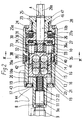
Figur 2- einen Axialschnitt der Spannvorrichtung,
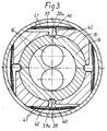
Figur 3- einen Querschnitt derselben nach der Linie III-III
der
Figur 2.
- Figure 1
- a longitudinal section of a machine vice with the clamping device used therein,
- Figure 2
- an axial section of the clamping device,
- Figure 3
- a cross section of the same along the line III-III of Figure 2.
Der in der Zeichnung dargestellte Maschinenschraubstock
weist eine Grundplatte 1 mit einer festen Spannbacke 2
auf. An dem Grundkörper 1 ist ein Spannschieber 3 in
Richtung S verschiebbar gelagert, der die bewegliche
Spannbacke 4 trägt. In dem Grundkörper 1 ist außerdem
eine Mutter 5 angeordnet, die über einen Querbolzen 6
gegenüber dem Grundkörper an verschiedenen Stellen
festlegbar ist. Deshalb ist die Mutter 5 als stationäre
Mutter bezeichnet. Die Spannvorrichtung 7 ist in einer
Längsbohrung 8 des Spannschiebers 3 drehbar gelagert.
Ihr konstruktiver Aufbau ist in den Figuren 2 und 3
näher dargestellt.The machine vice shown in the drawing
has a base plate 1 with a
Die Spannvorrichtung 7 weist eine Gewindespindel 9 auf,
die in der stationären Mutter 5 des Maschinenschraubstockes
verschraubbar ist. Koaxial zur Gewindespindel 9
ist ein im wesentlichen zylindrisches Gehäuse 10 vorgesehen,
dieses Gehäuse 10 umschließt einen weiter unten
noch näher beschriebenen Kraftverstärker und weist an
seinem der Schraubspindel zugekehrten vorderen Ende
einen koaxialen zylindrischen, hohlen Ansatz 11 auf.
Der Durchmesser dieses Ansatzes 11 ist kleiner als der
des Gehäuses 10. Mit diesem Ansatz 11 ist das Gehäuse 10
in der Längsbohrung 8 des Spannschiebers 3 drehbar gelagert.
Die Gewindespindel 9 weist an ihrem einen Ende 9a
ein feineres Gewinde 12 auf, mit dem sie fest in den
Ansatz 11 eingeschraubt ist. Hierdurch ist die Gewindespindel
9 drehfest mit dem Gehäuse 10 verbunden.The
Der vom Gehäuse 10 umschlossene Kraftverstärker besteht
im wesentlichen aus einem ersten Spannglied 13, einem
zweiten Spannglied 14, zwei zwischen diesen angeordneten
Spannbolzen 15 und vier Kugeln 16. Die Spannbolzen 15
weisen an ihren beiden Enden je eine Kugelpfanne auf,
in welche die Kugel 16 eingreift. Die beiden Spannglieder
13 und 14 sind mit halbkugelförmigen Vertiefungen
versehen, in welche die Kugeln 16 eingreifen. Gegebenenfalls
können die Spannbolzen 15 an ihren Enden auch
halbkugelförmig ausgestaltet sein, wobei dann die Kugeln
16 entfallen. The power amplifier enclosed by the
In Figur 2 ist die Spannvorrichtung in ihrer Ausgangsstellung, d.h. in Entspannstellung, dargestellt. Hierbei ist das zweite Spannglied 14 um etwa 52° gegenüber dem ersten Spannglied 13 verdreht. Die Spannbolzen 15 sind infolgedessen verschränkt oder in spitzem Winkel zur Gehäuseachse A geneigt angeordnet. Lediglich der Übersichtlichkeit halber sind in Figur 2 die Spannbolzen 15 in einer zur Gehäuseachse A parallelen Lage dargestellt, die sie in Spannstellung einnehmen.In Figure 2, the clamping device is in its initial position, i.e. shown in relaxation position. Here is the second tendon 14 by about 52 ° opposite twisted the first tendon 13. The clamping bolts 15 are consequently entangled or at an acute angle arranged inclined to the housing axis A. Only the For the sake of clarity, the clamping bolts are shown in FIG 15 in a position parallel to the housing axis A. shown, which they occupy in the clamping position.
Das erste Spannglied 13 ist im Gehäuse 10 axial verschiebbar,
jedoch gegenüber dem Gehäuse 10 drehfest gelagert.
Im vorderen, der Schraubspindel 9 zugekehrten Ende 10a
des Gehäuses 10 ist ein Druckring 17 axial verschiebbar.
Dieser Druckring 17 liegt einerseits an einer Ringfläche
18 des Spannschiebers 3 und andererseits an mehreren
Druckbolzen 19 an, die in axialen Bohrungen 20 des Gehäuses
10 verschiebbar sind. An diesen Druckbolzen 20
stützt sich das erste Spannglied 13 ab. Einer dieser
Druckbolzen 20 kann etwa länger ausgebildet sein und
in eine Ausnehmung 21 des Spanngliedes 13 eingreifen,
wodurch letzteres gegenüber dem Gehäuse 10 drehfest ist.
Es könnte jedoch auch ein separater Stift als Verdrehsicherung
vorgesehen sein. Ferner ist in dem hohlen
Ansatz 11 eine Druckfeder 22 angeordnet, die sich an
dem Ende 9a der Schraubspindel 9 abstützt. Die Druckfeder
22 wirkt auf das erste Spannglied 13 und übt
damit auf dieses einen in Richtung auf das zweite
Spannglied 14 gerichteten Druck aus.The first tendon 13 is axially displaceable in the
Das zweite Spannglied 14 ist in dem Gehäuse 10 begrenzt
drehbar gelagert.The second tendon 14 is limited in the
Am hinteren Ende 10b des Gehäuses ist eine im Prinzip
bekannte Spannkrafteinstellvorrichtung 23 (vgl. z.B.
DE 37 29 093 C1) angeordnet. Diese besteht aus einer in
die Endplatte 24 des Gehäuses eingeschraubten Stellschraube
25, mehreren kräftigen Tellerfedern 26 und
einer Widerlagerscheibe 27. Durch Verdrehung der Stellschraube
25 kann in Entspannstellung der Vorrichtung der
Abstand zwischen dem vorderen Ende 25a der Stellschraube
25 und dem hinteren Ende 27a der Widerlagerscheibe 27
und damit die maximale Spannkraft der Spannvorrichtung
eingestellt werden. Je größer der ursprüngliche Abstand
ist, desto kleiner ist die erreichbare Spannkraft. Da
in der gezeigten Stellung die beiden Flächen 25a und
27a aneinanderliegen, ist die Vorrichtung auf die maximale
Spannkraft eingestellt.In principle, there is one at the
In der Stellschraube 25 ist eine Antriebswelle 28 drehbar,
an deren äußerem Ende 28a eine Handkurbel 29 ansetzbar
ist. Zwischen dieser Antriebswelle 28 und dem
zweiten Spannglied 14 ist ein Planetengetriebe 30
zwischengeschaltet. Das Sonnenrad 31 dieses Planetengetriebes
wird durch eine entsprechende Verzahnung am
vorderen Ende der Antriebswelle 28 gebildet. Das Hohlrad
32 ist mit dem Gehäuse 10 verbunden bzw. es bildet
vorteilhaft einen Bestandteil des Gehäuses 10. Das
zweite Spannglied 14 bildet den Steg des Planetengetriebes
30. Zu diesem Zweck sind mehrere Lagerzapfen
33, die zur drehbaren Lagerung der Planetenräder 34
dienen, in entsprechende Ausnehmungen 35 des zweiten
Spanngliedes 14 eingesetzt. Die Lagerzapfen 33 stehen
an den dem zweiten Spannglied 14 abgewandten Seiten
der Planetenräder geringfügig vor und stützen sich an
einer Druckscheibe 36a ab. Zwischen dieser Druckscheibe
36a und der Widerlagerscheibe 27 ist ein Axiallager 36
angeordnet. A
Vervollständigt wird die Spannvorrichtung durch eine
Rastkupplung 38, die zwischen dem Gehäuse 10 und dem
zweiten Spannglied 14 wirksam ist. Diese Rastkupplung
38 weist mehrere in Umfangsrichtung des Gehäuses versetzt
zueinander angeordnete Rastelemente 39 auf,
die in radial verlaufenden Ausnehmungen 40 radial beweglich
sind und durch die Kraft der Blattfedern 41
radial nach innen belastet sind. Die Rastelemente 39
greifen mit ihren inneren, prismaförmig ausgebildeten
Enden 39a in entsprechende prismaförmige Nuten 42 am
Umfang des zweiten Spanngliedes 14 ein. Anstelle derartiger
Rastelemente 39 mit prismaförmigen Enden könnten
die Rastelemente auch als Kugeln ausgebildet sein,
die durch Schraubenfedern in entsprechende kegelstumpfförmige
Vertiefungen am Umfang des zweiten Spanngliedes
14 eingreifen.The tensioning device is completed by a
Um das Eindringen von Kühlschmiermittel, Spänen und
sonstigen Verunreinigungen in das Gehäuse 10 zu verhindern,
ist der Druckring 17 zweckmäßig durch O-Ringe
43, 44 gegenüber dem Gehäuse 10 und dem Ansatz 11 abgedichtet.
Ebenso sind zweckmäßig auch die übrigen, gegenüber
dem Gehäuse 10 beweglichen und aus diesem herausgeführten
Teile, wie z.B. die Stellschraube 25 und die
Antriebsspindel 28, durch O-Ringe 46, 47 abgedichtet.
Hierdurch ist es auch möglich, das Gehäuse 10 vollständig
mit Öl zu füllen. Dieses Öl wirkt nicht nur als
Schmiermittel für alle im Gehäuse 10 befindlichen
Teile, sondern das Öl verhindert auch das Eindringen
von Kühlschmiermittel und Spänen in das Gehäuse.To prevent the penetration of coolant, chips and
to prevent other impurities in the
Die Wirkungsweise ist folgende:The mode of action is as follows:
Mittels einer an die Antriebswelle 28 angesetzten Handkurbel
29 kann die Antriebswelle gedreht werden. Da zunächst
das zweite Spannglied 14 mittels der Rastkupplung
38 mit dem Gehäuse 10 drehfest gekuppelt ist, ist
das Planetengetriebe 30 blockiert. Bei Drehung der Antriebswelle
28 wird daher das Gehäuse 10 im Verhältnis
1 : 1 mitgedreht und damit auch die mit dem Ansatz 11
drehfest verbundene Schraubspindel 9. Die Schraubspindel
9 wird in der Mutter 5 verschraubt, wobei sich die
Schraubspindel 9 beim Spannen gemäß Figur 1 nach links
verschiebt. Hierbei liegt der Druckring 17 an der Ringfläche
18 des Spannschiebers 3 an und schiebt diesen
ebenfalls nach links bis seine Spannbacke 4 am Werkstück
anliegt. Dank der Rastkupplung 38 wird die bewegliche
Spannbacke 4 mit einer vorbestimmten Vorspannkraft an
das Werkstück W angedrückt. Damit ist der Zustellhub
des Spannschiebers 3 beendet. Bei weiterer Drehung der
Handkurbel 29 wird das durch die Rastkupplung 38 übertragbare
Drehmoment überschritten und die Rastelemente
39 werden entgegen der Federkraft 41 radial nach außen
gedrückt und rasten aus den Rastausnehmungen 42 aus.
Es kann sich nunmehr das zweite Spannglied 14 gegenüber
dem Gehäuse 10 verdrehen. Hierbei wird das zweite
Spannglied 14 über die Teile des Planetengetriebes 30
angetrieben, indem die Antriebswelle 28 über das Sonnenrad
31 die Planetenräder 34 antreibt, die an dem nunmehr
ruhenden Hohlrad 32 des Gehäuses abrollen. Hierdurch
werden die Lagerzapfen 33 in Umfangsrichtung gedreht
und drehen dabei auch das zweite Spannglied 14
gegenüber dem durch das Gehäuse 10 festgehaltenen ersten
Spannglied 13. Durch die gegenseitige Verdrehung der
beiden Spannglieder 13, 14 werden die Spannbolzen 15
aufgerichtet, d.h. ihre Verschränkung oder ihr spitzer
Winkel gegenüber der Gehäuseachse A nimmt ab. Durch
dieses Aufrichten der Spannbolzen 15 vergrößert sich
der Abstand zwischen den beiden Spanngliedern 13, 14.
Da das zweite Spannglied 14 über die Lagerzapfen 33,
die Druckscheibe 35, das Axiallager 36, die Widerlagerscheibe
37 und die Stellschraube 25 in axialer Richtung
gegenüber dem Gehäuse 10 abgestützt ist und nicht nach
rechts ausweichen kann, wird das erste Spannglied 13
im Gehäuse 10 nach links verschoben. Das erste Spannglied
13 drückt über die Druckbolzen 19 auf den Druckring
17 und dieser drückt den Spannschieber mit hohem
Druck nach links gegen das Werkstück W. Dies wird als
Spannhub bezeichnet. Infolge des Untersetzungsverhältnisses
des Planetengetriebes kann die Handkurbel 29
während des Spannhubes um etwa 330° gedreht werden, bis
die Achsen der Spannbolzen 15 parallel zur Gehäuseachse
A verlaufen. Die Drehung der Handkurbel 29 und damit die
Drehung des zweiten Spanngliedes 14 wird jedoch noch
weiter fortgesetzt, bis die Achsen der Spannbolzen 15
über ihre parallel zur Gehäuseachse A verlaufenden Totpunktlage
hinaus um etwa 3° entgegengesetzt zu ihrer Ausgangsstellung
gegenüber der Gehäuseachse A geneigt sind. Durch
die Bewegung der Spannbolzen 15 über ihre parallele Lage
zur Gehäuseachse A, d.h. über ihre Totpunktlage hinaus,
wird eine sichere Verriegelung des Kraftverstärkers und
damit der Spannvorrichtung erreicht. Zur Bewegung der
Spannbolzen 15 über die Totpunktlage hinaus muß die
Handkurbel 29 um etwa 30° weitergedreht werden. Da
hierbei die an der Handkurbel aufzuwendende Kraft nicht
weiter ansteigt, sondern im Gegenteil etwas abnimmt,
kann man hieran leicht erkennen, daß die Spannvorrichtung
nunmehr ihre endgültige verriegelte Spannstellung
erreicht hat.By means of a hand crank attached to the
Das Entspannen der Spannvorrichtung erfolgt durch Rückwärtsdrehung
der Handkurbel 29. Hierbei wird über das
Planetengetriebe 30 zunächst das zweite Spannglied 14
in entgegengesetzter Richtung gegenüber dem ersten
Spannglied 13 verdreht, bis die Spannbolzen 14 wieder
ihre gegenüber der Gehäuseachse A verschränkte Stellung
eingenommen haben und die Rastelemente 39 der Rastkupplung
38 in ihre Rastvertiefungen 42 eingeschnappt sind.
Bevor die Rastelemente 39 wieder in ihre Rastvertiefungen
42 einschnappen, liegen sie am Umfang des zweiten
Spanngliedes 14 an und werden durch die Federn 41 gegen
den Umfang gedrückt, wodurch zwischen diesen und den
Rastelementen 39 Gleitreibung entsteht. Hierdurch wird
bei der anfänglichen Rückwärtsdrehung der Handkurbel
das zweite Spannglied 14 gebremst und ein Zurückschnellen
der Handkurbel 29 verhindert, falls man diese nicht
richtig festhält oder losläßt. Während der Verdrehung des
zeiten Spanngliedes 14 gegenüber dem ersten Spannglied 13
sorgt die Druckfeder 22 dafür, daß das erste Spannglied
13 nach rechts verschoben und die Kugeln 16 in ständiger
Anlage an den Spannbolzen 15 gehalten werden. Wenn die
Rastkupplung 38 wieder eingerastet ist, ist das Planetengetriebe
30 wieder blockiert und das Gehäuse 10 sowie die
Schraubspindel 9 werden mittels der Handkurbel 29 wieder
im Verhältnis 1 : 1 gedreht. Die Schraubspindel 9 bewegt
sich jetzt von links nach rechts. Durch die am linken
Ende der Schraubspindel 9 vorgesehene Beilagscheibe 48
wird nunmehr der Spannschieber 3 mitgenommen und nach
rechts bewegt.The tensioning device is released by turning it backwards
the crank handle 29
Claims (10)
- A clamping device with a mechanical force amplifier,with a threaded spindle (9) which acts in particular on a movable clamping slide (3) of a machine vice or the like and can be screwed into a stationary nut (5) thereof,a substantially cylindrical housing (10) enclosing the force amplifier and arranged coaxial with the threaded spindle (9) and connected rotationally fast therewith,a first clamping member (13) axially slidable in the housing (10) and connected rotationally fast therewith, whose one end acts on a thrust element (17) bearing on the clamping slide (3),a second clamping member (14) arranged to rotate within limits in the housing (10),a plurality of tightening pins (15) arranged between the clamping members (13, 14), which pins are inclined at an acute angle to a plane running through the axis of the housing in one limit position (relaxed position) of the second clamping member (14) and are approximately parallel to this plane in the other limit position (clamping position),a spring arrangement (22) for moving the two clamping members (13, 14) towards one another, a thrust bearing (36) supporting the second clamping member (14) axially relative to the housing (10) anda drive shaft acting on the second clamping member and arranged coaxial with the housing,
characterized in that a planetary gear (30) is arranged between the second clamping member (14) and the drive shaft (28), with its sun wheel (31) arranged on the drive shaft (28), its annulus (32) attached to the housing (10) and its carrier formed by the second clamping member (14), wherein bearing pins (33) for the planet wheels (34) engage in the rear side of the second clamping member (14) facing away from the tightening pins (15), and in that a spring-loaded detent coupling (38) is provided between the housing (10) and the second clamping member (14). - A clamping device according to claim 1, characterized in that the bearing pins (33) project on the sides of the planet wheels (34) remote from the second clamping member (14) and bear directly or indirectly on the thrust bearing (36).
- A clamping device according to claim 2, characterized in that the bearing pins (33) bear on a thrust washer (36a) arranged between them and the thrust (36).
- A clamping device according to any of claims 1 to 3, characterized in that the detent coupling (38) has a plurality of detent elements (39) offset from one another in the circumferential direction of the housing (10) and which are radially movable in radially extending recesses (40) of the housing (10), are biased radially inwards by spring force (41) and engage with their inner ends (39a) in corresponding detent depressions (42) in the second clamping member.
- A clamping device according to claim 4, characterized in that the inner ends (39a) of the detent elements (39) are of prismatic shape and engage in prismatic grooves (42) in the second clamping member (14).
- A clamping device according to any of claims 1 to 5, characterized in that the thrust element is a thrust ring (17) arranged at the front end (10a) of the housing (10) and in that a plurality of thrust pins (19) are arranged between this ring and the first clamping member (13) and can slide in axial bores (20) in the housing (10).
- A clamping device according to claim 6, characterized in that the thrust ring (17) bears on an annular surface (18) of the clamping slide (3), which is disposed in the region of the rear end thereof, remote from the clamping jaw (4).
- A clamping device according to any of claims 1 to 7, characterized in that the housing (10) has a coaxial, cylindrical, hollow extension (11) on its front end (10a) facing the screw spindle (9), with a smaller diameter than the housing diameter, in that the end (9a) of the screw spindle (9) is screwed into this extension (11) and in that a compression spring (22) is arranged in the extension (11) and bears on the first clamping member (13).
- A clamping device according to claim 8, characterized in that the compression spring (22) bears on the end (9a) of the screw spindle (9).
- A clamping device according to any of claims 1 to 9, characterized in that the thrust ring (17) is sealed relative to the housing (10) and the extension (11) by D-rings (43, 44).
Applications Claiming Priority (2)
| Application Number | Priority Date | Filing Date | Title |
|---|---|---|---|
| DE19615335A DE19615335C1 (en) | 1996-04-18 | 1996-04-18 | Clamping device with mechanical power amplifier |
| DE19615335 | 1996-04-18 |
Publications (2)
| Publication Number | Publication Date |
|---|---|
| EP0802022A1 EP0802022A1 (en) | 1997-10-22 |
| EP0802022B1 true EP0802022B1 (en) | 1999-06-09 |
Family
ID=7791646
Family Applications (1)
| Application Number | Title | Priority Date | Filing Date |
|---|---|---|---|
| EP97103816A Expired - Lifetime EP0802022B1 (en) | 1996-04-18 | 1997-03-07 | Clamping device with a mechanical power booster |
Country Status (7)
| Country | Link |
|---|---|
| US (1) | US5813666A (en) |
| EP (1) | EP0802022B1 (en) |
| JP (1) | JP3011903B2 (en) |
| KR (1) | KR100397294B1 (en) |
| AT (1) | ATE181011T1 (en) |
| DE (2) | DE19615335C1 (en) |
| ES (1) | ES2134038T3 (en) |
Families Citing this family (10)
| Publication number | Priority date | Publication date | Assignee | Title |
|---|---|---|---|---|
| GB9912268D0 (en) * | 1999-05-27 | 1999-07-28 | Meltog Ltd | Axial displacement mechanism |
| KR100706518B1 (en) * | 2002-03-28 | 2007-04-11 | 주식회사 만도 | Floating jig for hornning of valve body |
| JP4899083B2 (en) * | 2005-08-29 | 2012-03-21 | Smc株式会社 | Automatic reduction ratio switching device |
| JP4789000B2 (en) * | 2006-02-16 | 2011-10-05 | Smc株式会社 | Automatic reduction ratio switching device |
| TW200829370A (en) * | 2007-01-02 | 2008-07-16 | Hold Well Ind Co Ltd | Power vise |
| DE202010010867U1 (en) * | 2010-07-30 | 2011-11-02 | Gressel Ag | Clamping device with power amplification |
| CN102996739B (en) * | 2011-09-15 | 2015-07-29 | 上海团结普瑞玛激光设备有限公司 | Flexible lead screw pre-tightening device |
| WO2014141432A1 (en) * | 2013-03-14 | 2014-09-18 | 株式会社カワタテック | Feed structure and gripping device with same |
| JP6045947B2 (en) * | 2013-03-14 | 2016-12-14 | 株式会社カワタテック | Feed structure and gripping device provided with the same |
| CN116495405B (en) * | 2023-06-28 | 2023-10-10 | 四川英创力电子科技股份有限公司 | Circuit board conveying and clamping device and using method thereof |
Family Cites Families (11)
| Publication number | Priority date | Publication date | Assignee | Title |
|---|---|---|---|---|
| DE575658C (en) * | 1930-12-18 | 1933-05-02 | Hermann Manthey | Quick release and quick lifting device for machine vices, brakes, control devices, etc. like |
| CH258940A (en) * | 1946-01-16 | 1948-12-31 | Roth Alfred | Device for driving screw gears. |
| DE1283168B (en) * | 1964-12-01 | 1968-11-14 | Franz Arnold | Mechanical clamping device for generating a high clamping force |
| DE3329295A1 (en) * | 1983-08-12 | 1985-02-28 | Alfing Montagetechnik GmbH, 7080 Aalen | Motor-driven screwdriving tool |
| SE439349B (en) * | 1983-10-04 | 1985-06-10 | Per John Karlsson | REVERSIBLE Torque Converters |
| DE8711795U1 (en) * | 1987-09-01 | 1988-12-29 | Gressel Ag, Aadorf, Thurgau, Ch | |
| DE4018284C1 (en) * | 1990-06-07 | 1991-04-18 | Gressel Ag, Aadorf, Thurgau, Ch | |
| DE4112547A1 (en) * | 1991-04-17 | 1992-10-22 | Gressel Ag | CLAMPING FORCE ADJUSTMENT FOR A CLAMPING DEVICE |
| DE9104681U1 (en) * | 1991-04-17 | 1992-08-13 | Gressel Ag, Aadorf, Ch | |
| DE4127772C2 (en) * | 1991-08-22 | 1996-06-05 | Kesel Georg Gmbh & Co Kg | Mechanical booster |
| US5399129A (en) * | 1993-06-07 | 1995-03-21 | Ciolli; Donald A. | Wrap spring downshift mechanism |
-
1996
- 1996-04-18 DE DE19615335A patent/DE19615335C1/en not_active Expired - Fee Related
-
1997
- 1997-03-07 EP EP97103816A patent/EP0802022B1/en not_active Expired - Lifetime
- 1997-03-07 AT AT97103816T patent/ATE181011T1/en not_active IP Right Cessation
- 1997-03-07 ES ES97103816T patent/ES2134038T3/en not_active Expired - Lifetime
- 1997-03-07 DE DE59700195T patent/DE59700195D1/en not_active Expired - Lifetime
- 1997-03-19 US US08/821,800 patent/US5813666A/en not_active Expired - Lifetime
- 1997-04-17 JP JP9099965A patent/JP3011903B2/en not_active Expired - Lifetime
- 1997-04-17 KR KR1019970014187A patent/KR100397294B1/en not_active IP Right Cessation
Also Published As
| Publication number | Publication date |
|---|---|
| ATE181011T1 (en) | 1999-06-15 |
| KR970069246A (en) | 1997-11-07 |
| DE59700195D1 (en) | 1999-07-15 |
| US5813666A (en) | 1998-09-29 |
| ES2134038T3 (en) | 1999-09-16 |
| DE19615335C1 (en) | 1997-10-02 |
| JP3011903B2 (en) | 2000-02-21 |
| KR100397294B1 (en) | 2003-12-31 |
| JPH1034549A (en) | 1998-02-10 |
| EP0802022A1 (en) | 1997-10-22 |
Similar Documents
| Publication | Publication Date | Title |
|---|---|---|
| EP0330672B1 (en) | Clamping device for axially tightening a tool, in particular a disk | |
| EP0480299B1 (en) | Multiple clamping device for clamping at least two workpieces | |
| DE3541922C1 (en) | Pipe socket screwing machine | |
| DE102004043146B3 (en) | Hydraulic bolt tensioning device | |
| EP2837466B1 (en) | Clamping unit, in particular for use in a machining centre or a turning or milling center | |
| DE3643067A1 (en) | TENSIONING DEVICE FOR AXIAL CLAMPING OF A TOOL, IN PARTICULAR A DISC | |
| DE3638526C1 (en) | Workpiece clamping device that can be driven by an electric motor | |
| EP0802022B1 (en) | Clamping device with a mechanical power booster | |
| DE4018284C1 (en) | ||
| DE3603618C1 (en) | Clamping device for use on machine tools | |
| EP0580639B1 (en) | Chuck | |
| DE3439668C2 (en) | ||
| DE2805881A1 (en) | CLAMPING PIN FOR COAXIAL MACHINING OF WORKPIECES WITH INTERNAL GEAR | |
| DE3729093C1 (en) | Clamping device with mechanical power amplifier | |
| DE10241860A1 (en) | Clamping device for tool with hollow conical shaft, comprising combination of transversally positioned operating element and hemispherical swivel element | |
| DE19708586B4 (en) | Complementary device for a spring compressor and method for relaxing a spring | |
| EP0250638A1 (en) | Clamp for compression spring | |
| DE2953734C1 (en) | Device for tightening coarse thread connections | |
| DE3911073C1 (en) | ||
| DE1283168B (en) | Mechanical clamping device for generating a high clamping force | |
| DE1900835A1 (en) | Mechanical-hydraulic clamping device | |
| DE3509922C1 (en) | Clamping device for fastening a work holder or the like to a spindle | |
| EP0340602B1 (en) | Drive for a machine vice | |
| DE956732C (en) | Chuck for the center drive of a workpiece to be machined on a lathe | |
| DE3306809C1 (en) | Drilling rigs |
Legal Events
| Date | Code | Title | Description |
|---|---|---|---|
| PUAI | Public reference made under article 153(3) epc to a published international application that has entered the european phase |
Free format text: ORIGINAL CODE: 0009012 |
|
| AK | Designated contracting states |
Kind code of ref document: A1 Designated state(s): AT BE CH DE ES FR GB IT LI NL SE |
|
| 17P | Request for examination filed |
Effective date: 19980327 |
|
| GRAG | Despatch of communication of intention to grant |
Free format text: ORIGINAL CODE: EPIDOS AGRA |
|
| GRAH | Despatch of communication of intention to grant a patent |
Free format text: ORIGINAL CODE: EPIDOS IGRA |
|
| 17Q | First examination report despatched |
Effective date: 19980729 |
|
| GRAH | Despatch of communication of intention to grant a patent |
Free format text: ORIGINAL CODE: EPIDOS IGRA |
|
| GRAA | (expected) grant |
Free format text: ORIGINAL CODE: 0009210 |
|
| AK | Designated contracting states |
Kind code of ref document: B1 Designated state(s): AT BE CH DE ES FR GB IT LI NL SE |
|
| REF | Corresponds to: |
Ref document number: 181011 Country of ref document: AT Date of ref document: 19990615 Kind code of ref document: T |
|
| REG | Reference to a national code |
Ref country code: CH Ref legal event code: EP |
|
| ET | Fr: translation filed | ||
| REF | Corresponds to: |
Ref document number: 59700195 Country of ref document: DE Date of ref document: 19990715 |
|
| GBT | Gb: translation of ep patent filed (gb section 77(6)(a)/1977) |
Effective date: 19990702 |
|
| REG | Reference to a national code |
Ref country code: CH Ref legal event code: NV Representative=s name: DIPL.-ING. W. STEUDTNER |
|
| ITF | It: translation for a ep patent filed |
Owner name: BIANCHETTI - BRACCO - MINOJA S.R.L. |
|
| REG | Reference to a national code |
Ref country code: ES Ref legal event code: FG2A Ref document number: 2134038 Country of ref document: ES Kind code of ref document: T3 |
|
| PLBE | No opposition filed within time limit |
Free format text: ORIGINAL CODE: 0009261 |
|
| STAA | Information on the status of an ep patent application or granted ep patent |
Free format text: STATUS: NO OPPOSITION FILED WITHIN TIME LIMIT |
|
| 26N | No opposition filed | ||
| REG | Reference to a national code |
Ref country code: GB Ref legal event code: IF02 |
|
| PGFP | Annual fee paid to national office [announced via postgrant information from national office to epo] |
Ref country code: ES Payment date: 20080220 Year of fee payment: 12 |
|
| REG | Reference to a national code |
Ref country code: CH Ref legal event code: PCAR Free format text: PATENTANWALTSBUREAU STEUDTNER;AHORNWEG 12;5702 NIEDERLENZ (CH) |
|
| PGFP | Annual fee paid to national office [announced via postgrant information from national office to epo] |
Ref country code: GB Payment date: 20080305 Year of fee payment: 12 Ref country code: SE Payment date: 20080306 Year of fee payment: 12 |
|
| PGFP | Annual fee paid to national office [announced via postgrant information from national office to epo] |
Ref country code: FR Payment date: 20080225 Year of fee payment: 12 |
|
| PGFP | Annual fee paid to national office [announced via postgrant information from national office to epo] |
Ref country code: AT Payment date: 20090325 Year of fee payment: 13 |
|
| PGFP | Annual fee paid to national office [announced via postgrant information from national office to epo] |
Ref country code: NL Payment date: 20090227 Year of fee payment: 13 |
|
| PGFP | Annual fee paid to national office [announced via postgrant information from national office to epo] |
Ref country code: BE Payment date: 20090408 Year of fee payment: 13 |
|
| EUG | Se: european patent has lapsed | ||
| GBPC | Gb: european patent ceased through non-payment of renewal fee |
Effective date: 20090307 |
|
| REG | Reference to a national code |
Ref country code: FR Ref legal event code: ST Effective date: 20091130 |
|
| PG25 | Lapsed in a contracting state [announced via postgrant information from national office to epo] |
Ref country code: GB Free format text: LAPSE BECAUSE OF NON-PAYMENT OF DUE FEES Effective date: 20090307 Ref country code: FR Free format text: LAPSE BECAUSE OF NON-PAYMENT OF DUE FEES Effective date: 20091123 |
|
| REG | Reference to a national code |
Ref country code: ES Ref legal event code: FD2A Effective date: 20090309 |
|
| PG25 | Lapsed in a contracting state [announced via postgrant information from national office to epo] |
Ref country code: ES Free format text: LAPSE BECAUSE OF NON-PAYMENT OF DUE FEES Effective date: 20090309 |
|
| BERE | Be: lapsed |
Owner name: *GRESSEL A.G. Effective date: 20100331 |
|
| REG | Reference to a national code |
Ref country code: NL Ref legal event code: V1 Effective date: 20101001 |
|
| PG25 | Lapsed in a contracting state [announced via postgrant information from national office to epo] |
Ref country code: AT Free format text: LAPSE BECAUSE OF NON-PAYMENT OF DUE FEES Effective date: 20100307 |
|
| PG25 | Lapsed in a contracting state [announced via postgrant information from national office to epo] |
Ref country code: NL Free format text: LAPSE BECAUSE OF NON-PAYMENT OF DUE FEES Effective date: 20101001 |
|
| PG25 | Lapsed in a contracting state [announced via postgrant information from national office to epo] |
Ref country code: BE Free format text: LAPSE BECAUSE OF NON-PAYMENT OF DUE FEES Effective date: 20100331 |
|
| PG25 | Lapsed in a contracting state [announced via postgrant information from national office to epo] |
Ref country code: SE Free format text: LAPSE BECAUSE OF NON-PAYMENT OF DUE FEES Effective date: 20090308 |
|
| PGFP | Annual fee paid to national office [announced via postgrant information from national office to epo] |
Ref country code: IT Payment date: 20110324 Year of fee payment: 15 |
|
| REG | Reference to a national code |
Ref country code: CH Ref legal event code: PCAR Free format text: PATENTANWALTSBUERO STEUDTNER;AHORNWEG 6;5702 NIEDERLENZ (CH) |
|
| PG25 | Lapsed in a contracting state [announced via postgrant information from national office to epo] |
Ref country code: IT Free format text: LAPSE BECAUSE OF NON-PAYMENT OF DUE FEES Effective date: 20120307 |
|
| PGFP | Annual fee paid to national office [announced via postgrant information from national office to epo] |
Ref country code: CH Payment date: 20130306 Year of fee payment: 17 |
|
| PGFP | Annual fee paid to national office [announced via postgrant information from national office to epo] |
Ref country code: DE Payment date: 20130508 Year of fee payment: 17 |
|
| REG | Reference to a national code |
Ref country code: CH Ref legal event code: PCAR Free format text: NEW ADDRESS: ALBULAGASSE 8, 5200 BRUGG/AG (CH) |
|
| REG | Reference to a national code |
Ref country code: DE Ref legal event code: R119 Ref document number: 59700195 Country of ref document: DE |
|
| REG | Reference to a national code |
Ref country code: CH Ref legal event code: PL |
|
| REG | Reference to a national code |
Ref country code: DE Ref legal event code: R119 Ref document number: 59700195 Country of ref document: DE Effective date: 20141001 |
|
| PG25 | Lapsed in a contracting state [announced via postgrant information from national office to epo] |
Ref country code: LI Free format text: LAPSE BECAUSE OF NON-PAYMENT OF DUE FEES Effective date: 20140331 Ref country code: DE Free format text: LAPSE BECAUSE OF NON-PAYMENT OF DUE FEES Effective date: 20141001 Ref country code: CH Free format text: LAPSE BECAUSE OF NON-PAYMENT OF DUE FEES Effective date: 20140331 |