EP0802013A1 - Welding mold and method - Google Patents
Welding mold and method Download PDFInfo
- Publication number
- EP0802013A1 EP0802013A1 EP97105749A EP97105749A EP0802013A1 EP 0802013 A1 EP0802013 A1 EP 0802013A1 EP 97105749 A EP97105749 A EP 97105749A EP 97105749 A EP97105749 A EP 97105749A EP 0802013 A1 EP0802013 A1 EP 0802013A1
- Authority
- EP
- European Patent Office
- Prior art keywords
- mold
- sleeving
- weld
- chamber
- passages
- Prior art date
- Legal status (The legal status is an assumption and is not a legal conclusion. Google has not performed a legal analysis and makes no representation as to the accuracy of the status listed.)
- Ceased
Links
- 238000003466 welding Methods 0.000 title claims abstract description 16
- 238000000034 method Methods 0.000 title claims description 7
- 239000002184 metal Substances 0.000 claims abstract description 22
- 239000000463 material Substances 0.000 claims abstract description 11
- 239000004020 conductor Substances 0.000 claims abstract description 8
- 230000013011 mating Effects 0.000 claims 1
- 238000013022 venting Methods 0.000 claims 1
- 238000012856 packing Methods 0.000 abstract description 7
- 238000005299 abrasion Methods 0.000 abstract description 2
- OKTJSMMVPCPJKN-UHFFFAOYSA-N Carbon Chemical compound [C] OKTJSMMVPCPJKN-UHFFFAOYSA-N 0.000 description 3
- 229910002804 graphite Inorganic materials 0.000 description 3
- 239000010439 graphite Substances 0.000 description 3
- 239000002893 slag Substances 0.000 description 3
- 239000000843 powder Substances 0.000 description 2
- 229910000831 Steel Inorganic materials 0.000 description 1
- 238000009434 installation Methods 0.000 description 1
- 239000011819 refractory material Substances 0.000 description 1
- 239000003566 sealing material Substances 0.000 description 1
- 239000010959 steel Substances 0.000 description 1
- 210000003813 thumb Anatomy 0.000 description 1
Images

Classifications
-
- B—PERFORMING OPERATIONS; TRANSPORTING
- B22—CASTING; POWDER METALLURGY
- B22D—CASTING OF METALS; CASTING OF OTHER SUBSTANCES BY THE SAME PROCESSES OR DEVICES
- B22D19/00—Casting in, on, or around objects which form part of the product
- B22D19/04—Casting in, on, or around objects which form part of the product for joining parts
-
- B—PERFORMING OPERATIONS; TRANSPORTING
- B23—MACHINE TOOLS; METAL-WORKING NOT OTHERWISE PROVIDED FOR
- B23K—SOLDERING OR UNSOLDERING; WELDING; CLADDING OR PLATING BY SOLDERING OR WELDING; CUTTING BY APPLYING HEAT LOCALLY, e.g. FLAME CUTTING; WORKING BY LASER BEAM
- B23K23/00—Alumino-thermic welding
Definitions
- This invention relates generally as indicated to a welding mold and method, and more particularly, to a reusable refractory mold and method for making electrical exothermic weld connections.
- Reusable refractory molds usually made of graphite or the like are widely used with exothermic welding materials to make a wide variety of high ampacity low resistance electrical connections.
- Typical of such molds are those sold under the well-known trademark CADWELD® by ERICO International of Solon, Ohio USA.
- Such reusable molds are two or more part molds usually opened and closed and held together by toggle clamps.
- the mold parts have faces which abut at a parting plane in which are formed recesses forming the various cavities and passages when the parts are clamped together.
- the mold parts form a weld chamber, which usually includes a riser which may be the enlarged lower end of a tap hole passage which extends from the top of the mold to the weld chamber.
- the parts to be welded enter the weld chamber through sleeving passages which extend from outside the mold to the weld chamber.
- Such passages usually extend horizontally or from the bottom.
- Horizontal passages are typically employed when welding cable-to-cable. They may be used in combination with a vertical passage when welding cable to an earthing rod, for example.
- a crucible normally sits on top of the assembled mold parts.
- the crucible includes a chamber holding the exothermic material on top of a fusible disc.
- a sprue or tap hole below the disc communicates with the top of the tap hole of the mold.
- Such molds can be rather intricate and are not insignificant in cost. The number of times a mold can be reused has a very direct impact on the cost of each weld connection. It has been found that the greatest wear on such molds occurs at the sleeving passages. This is particularly true where the sleeving passages accommodate stranded cable which may vary in size. With such cable, sealing material or packing must normally be employed to prevent the molten metal from leaking. Where the conductor is undersize the mold sleeving passage, adapter sleeves or shims around the conductors may be employed to fit the sleeving passage, and such may be used in combination with the packing material. All of the above adds to the cost of the weld.
- a mold for joining conductors such as stranded cable to each other and to other elements such as a ground rod is formed of two or more parts.
- the mold formed by the parts includes a weld chamber. Exothermic welding material in a crucible above forms molten metal which drops into the weld chamber through a tap hole.
- the mold includes sleeving passages extending upwardly at an angle from horizontal to exit the mold wall above the level of molten metal forming the weld. In this manner, the molten metal is contained within the weld cavity of the mold.
- the sleeving passages extending upwardly at an angle from the weld chamber, or as a V with two symmetrical passages, are preferably larger than normal passages and accordingly will accommodate a wide variety of cable sizes without interference with or abrasion of the sleeving passages. This enables one mold to accommodate more sizes, avoids the use of packing, adapter sleeves or shims, and maintains the weld chamber well vented. For a two, three or more cable connection, the mold system results in a two, three or more dimension V connection, joined at the crotch by the weld metal.
- the installation and operation of the parts are greatly simplified.
- the mold is closed before the cable ends are inserted in the V-shape sleeving passages.
- the ends are simply inserted in the sleeving passages until they abut the weld chamber or other cable inserted from another sleeving passage.
- the cables may be bent a short distance from their ends, and in effect hooked into the inclined sleeving passages. This holds the cable in place while the operator may assemble the crucible, charge it with exothermic welding material, and ignite such material, to form the molten metal for welding.
- the apparatus comprises a refractory crucible 21 formed of a refractory material such as graphite and containing a reaction chamber 22 open at the top as indicated at 23 in Fig. 4, beneath a refractory lid 24 hinged to the top of the crucible as indicated at 25.
- the crucible includes a projecting handle 26.
- the reaction chamber 22 funnels to a shoulder 30 and a bottom tap hole 31.
- a steel disc 32 sits on the shoulder 30 containing the charge of exothermic material 33.
- a starting powder may be sprinkled over the top of the charge 33 as indicated at 34. Some of the starting powder may be placed on the rim 35 so that the reaction may be initiated by an igniter through the opening formed by the arched roof 36 of the lid 24.
- the bottom of crucible 21 is seated on top of a mold assembly shown generally at 40 which may comprise two substantially identical refractory blocks 41 and 42 which are clamped together at a common parting plane seen at 43.
- the blocks are clamped together or opened and closed by a toggle clamp shown generally at 45.
- the toggle clamp includes two frames 46 and 47 seen in Figure 1 pivoted together as indicated at 48.
- Each frame is removably secured to respective blocks 41 and 42 by the projecting pins seen at 49 and 50 in Fig. 2 which project into the blocks.
- the frames are held locked in place by the thumb screws 52 and 53.
- Each toggle frame includes a handle indicated at 54 and 55 pivoted to the respective frames at 56 and 57.
- Each handle includes a right angle adjustable toggle linkage pivoted to each other at 58.
- each block at the common parting plans 43 shown at 60 for the block 41 includes a number of recesses which form certain passages and chambers when the blocks are clamped together.
- the exposed mold face will be described as though the recesses were formed since the opposite mold face is essentially identical.
- the tap hole 31 of the crucible communicates with a tap hole 62 in the mold assembly which leads to an enlarged central weld chamber 63.
- the tap hole may be slightly enlarged as indicated at 64 as it enters the weld chamber to form a riser.
- the riser 64 may be used to collect any slag on top of the molten metal which may be removed after the weld is made.
- Also entering the weld chamber are two inclined or V-shaped sleeving passages seen at 66 and 67.
- the sleeving passages extend upwardly at an angle to the horizontal of approximately 45° and the lower edge of each sleeving passage as it exits the mold assembly to atmosphere indicated at 68 is well above the weld chamber.
- a horizontal projection through the opening for such sleeving passages seen at 70 in Fig. 3 does not reveal the weld chamber.
- the inclined symmetrical sleeving passages 66 and 67 are intentionally oversized for the cable ends to be received into the welding chamber.
- the sleeving passages illustrated will accommodate cable from about 16 to about 50 square millimeters.
- Fig. 5 there is illustrated two of the larger cable ends 72 and 73 inserted into the weld chamber 63. It can be seen that the cable ends are inserted to a physical stop and no great care need be taken to ensure that the cable ends are centered or symmetrical. Even with the larger cable, substantial clearance is provided between the cable and the passage as seen at 74 and 75.
- Fig. 7 illustrates a smaller cable 77 introduced in passage 66 and a larger cable 73 introduced in passage 67.
- the cables have been provided with sleeving, shims, or packing.
- the cable ends have simply been inserted into the sleeving passages until they contact a physical stop, such as the weld chamber or the other cable end.
- Fig. 8 illustrates a mold assembly shown generally at 80 which permits two cables 77 and 78 to be welded to the top of a grounding or earthing rod 81.
- the mold assembly is provided with the tap hole 62, the weld chamber 63, and the inclined sleeving passages 66 and 67.
- the mold is also provided with a vertically extending passage 82 entering the weld chamber from the bottom.
- three cables can be welded to each other forming a three dimensional V by a three part mold assembly.
- the assembly shown generally in Fig. 9 at 86 includes the mold half such as seen at 41 in Figs. 5-7 behind two quarter mold parts 87 and 88.
- the quarter mold parts join the mold part 41 at the face 60 forming the sleeving passages 89 and 90 and they also join each other at the parting plane 91 forming the third sleeving passage 92.
- the third sleeving passage 92 like the others, is inclined to horizontal and the lower edge of the opening to atmosphere seen at 93 is well above the welding chamber.
- four cables can be connected with four mold parts.
- the mold parts may be held together by toggle clamps or other types of clamps.
- the reaction material 33 will be ignited.
- the reaction produces molten metal which fuses the disc 32 permitting the molten metal to drop into the weld chamber providing a high ampacity, low resistance electrical connection.
- Such connections are typical of the connections made with earthing or grounding applications.
- V-shape connection formed by the apparatus and process of the present invention is shown generally at 95 in Fig. 10.
- the connection includes the weld metal 96 forming a fused and molecular connection between the cables 77 and 78.
- the present invention permits the use of longer lived molds since the sleeving or shims normally employed would abrade the sleeving passages of the graphite molds.
- high ampacity, low resistance electrical connections can quickly be made without the use of shims, sleeving or packing, and the weld chamber is left vented to atmosphere.
- the cable ends are more easily inserted to a positive physical stop.
- the connections made are high quality electrical connections made more efficiently and economically with fewer parts.
Landscapes
- Engineering & Computer Science (AREA)
- Mechanical Engineering (AREA)
- Furnace Details (AREA)
- Molds, Cores, And Manufacturing Methods Thereof (AREA)
Abstract
A mold for joining conductors (72,73) such as stranded cable to each other and to other elements such as a ground rod is formed of two or more parts (41,42) The mold is formed by the parts includes a weld chamber (63). Exothermic welding material (33) in a crucible (21) above forms molten metal which drops into the weld chamber through a tap hole (31). The mold includes sleeving passages (66,67) extending upwardly at an angle from horizontal to exit the mold well above the level of molten metal forming the weld. The sleeving passages (66,67) extending upwardly at an angle from the weld chamber, or as a V with two symmetrical passages, are preferably larger than normal passages and accordingly will accommodate a wide variety of cable sizes without interference with or abrasion of the sleeving passages. This enables one mold to accommodate more sizes, avoids the use of packing, adapter sleeves or shims, and maintains the weld chamber well vented. For a two, three or more cable connection, the mold system results in a two, three or more dimension V connection, joined at the crotch by the weld metal.
Description
- This invention relates generally as indicated to a welding mold and method, and more particularly, to a reusable refractory mold and method for making electrical exothermic weld connections.
- Reusable refractory molds usually made of graphite or the like are widely used with exothermic welding materials to make a wide variety of high ampacity low resistance electrical connections. Typical of such molds are those sold under the well-known trademark CADWELD® by ERICO International of Solon, Ohio USA.
- Such reusable molds are two or more part molds usually opened and closed and held together by toggle clamps. The mold parts have faces which abut at a parting plane in which are formed recesses forming the various cavities and passages when the parts are clamped together. Typically the mold parts form a weld chamber, which usually includes a riser which may be the enlarged lower end of a tap hole passage which extends from the top of the mold to the weld chamber. The parts to be welded enter the weld chamber through sleeving passages which extend from outside the mold to the weld chamber. Such passages usually extend horizontally or from the bottom. Horizontal passages are typically employed when welding cable-to-cable. They may be used in combination with a vertical passage when welding cable to an earthing rod, for example.
- A crucible normally sits on top of the assembled mold parts. The crucible includes a chamber holding the exothermic material on top of a fusible disc. A sprue or tap hole below the disc communicates with the top of the tap hole of the mold. When a measured and controlled quantity of exothermic material is ignited, it forms molten metal which fuses the disc permitting the molten metal to run downwardly into the weld chamber to weld any parts exposed to the chamber. Any slag forms on top of the weld metal and normally accumulates in the riser. After the weld cools, the mold is disassembled and any slag removed. The mold and crucible are cleaned for reuse.
- Such molds can be rather intricate and are not insignificant in cost. The number of times a mold can be reused has a very direct impact on the cost of each weld connection. It has been found that the greatest wear on such molds occurs at the sleeving passages. This is particularly true where the sleeving passages accommodate stranded cable which may vary in size. With such cable, sealing material or packing must normally be employed to prevent the molten metal from leaking. Where the conductor is undersize the mold sleeving passage, adapter sleeves or shims around the conductors may be employed to fit the sleeving passage, and such may be used in combination with the packing material. All of the above adds to the cost of the weld.
- Although it is always recommended to preheat the mold before use to ensure no moisture comes in contact with the molten metal, it can be seen that this is less of a problem if the weld chamber is not sealed, but well vented, especially along the sleeving passages.
- For most connections, it is a time consuming job to locate the cable ends properly in the weld chamber beneath the tap hole, all properly sleeved, shimmed or sealed. Cable of considerable length and size is bulky and difficult to handle and keep in one place. This is particularly true where the operator is trying to close the mold parts properly on three cables or two cables and a ground rod, for example. Sometimes special cable clamps must be used. It would be very convenient if the operator could insert the cable ends into an already closed mold, and to a physical stop. It would also be convenient to have a mold system where the cable ends would stay where positioned as the operator proceeds with the welding operation. It can be seen that it would be highly advantageous to provide a mold system for electrical or earthing connections and the like which would readily accommodate different size cabling without the use of packing, adapter sleeves or shims and with minimal wear on the sleeving passages. It would also be desirable for the mold systems to maintain the weld chamber well vented to atmosphere.
- A mold for joining conductors such as stranded cable to each other and to other elements such as a ground rod is formed of two or more parts. The mold formed by the parts includes a weld chamber. Exothermic welding material in a crucible above forms molten metal which drops into the weld chamber through a tap hole. The mold includes sleeving passages extending upwardly at an angle from horizontal to exit the mold wall above the level of molten metal forming the weld. In this manner, the molten metal is contained within the weld cavity of the mold.
- The sleeving passages extending upwardly at an angle from the weld chamber, or as a V with two symmetrical passages, are preferably larger than normal passages and accordingly will accommodate a wide variety of cable sizes without interference with or abrasion of the sleeving passages. This enables one mold to accommodate more sizes, avoids the use of packing, adapter sleeves or shims, and maintains the weld chamber well vented. For a two, three or more cable connection, the mold system results in a two, three or more dimension V connection, joined at the crotch by the weld metal.
- The installation and operation of the parts are greatly simplified. The mold is closed before the cable ends are inserted in the V-shape sleeving passages. The ends are simply inserted in the sleeving passages until they abut the weld chamber or other cable inserted from another sleeving passage. The cables may be bent a short distance from their ends, and in effect hooked into the inclined sleeving passages. This holds the cable in place while the operator may assemble the crucible, charge it with exothermic welding material, and ignite such material, to form the molten metal for welding.
- To the accomplishment of the foregoing and related ends, the invention then comprises the features hereinafter fully described and particularly pointed out in the claims, the following description and the annexed drawings setting forth in detail certain illustrative embodiments of the invention, these being indicative, however, of but a few of the various ways in which the principles of the invention may be employed.
-
- Figure 1 is a top plan view of a mold assembly and crucible for forming electrical connections;
- Figure 2 is a side elevation of the assembly as seen from the bottom of Figure 1;
- Figure 3 is an elevation as seen from the left hand side of Figure 2;
- Figure 4 is a vertical section seen from the line 4-4 of Figure 3;
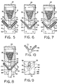
- Figure 5 is a similar section with two cables in place;
- Figure 6 is a similar view with two smaller cables;
- Figure 7 is a similar view with one smaller and one large cable;
- Figure 8 is a similar view of a mold system for welding two cables on top of a ground rod, for example;
- Figure 9 is an elevation of a three or four part mold system; and
- Figure 10 is fragmentary view of the connection made.
- Referring now to the drawings, and initially to Figs. 1-4, there is illustrated generally at 20 apparatus for forming an electrical connection in accordance with the present invention. The apparatus comprises a
refractory crucible 21 formed of a refractory material such as graphite and containing areaction chamber 22 open at the top as indicated at 23 in Fig. 4, beneath arefractory lid 24 hinged to the top of the crucible as indicated at 25. The crucible includes aprojecting handle 26. - As seen more clearly in Fig. 4, the
reaction chamber 22 funnels to ashoulder 30 and abottom tap hole 31. In operation asteel disc 32 sits on theshoulder 30 containing the charge ofexothermic material 33. A starting powder may be sprinkled over the top of thecharge 33 as indicated at 34. Some of the starting powder may be placed on therim 35 so that the reaction may be initiated by an igniter through the opening formed by thearched roof 36 of thelid 24. - The bottom of
crucible 21 is seated on top of a mold assembly shown generally at 40 which may comprise two substantially identicalrefractory blocks frames respective blocks pivots mold blocks pivots pivot 48 as the handles are separated. - Referring now to Fig. 4, it will be seen that the face of each block at the common parting plans 43 shown at 60 for the
block 41 includes a number of recesses which form certain passages and chambers when the blocks are clamped together. The exposed mold face will be described as though the recesses were formed since the opposite mold face is essentially identical. - The
tap hole 31 of the crucible communicates with atap hole 62 in the mold assembly which leads to an enlargedcentral weld chamber 63. The tap hole may be slightly enlarged as indicated at 64 as it enters the weld chamber to form a riser. Theriser 64 may be used to collect any slag on top of the molten metal which may be removed after the weld is made. Also entering the weld chamber are two inclined or V-shaped sleeving passages seen at 66 and 67. The sleeving passages extend upwardly at an angle to the horizontal of approximately 45° and the lower edge of each sleeving passage as it exits the mold assembly to atmosphere indicated at 68 is well above the weld chamber. A horizontal projection through the opening for such sleeving passages seen at 70 in Fig. 3 does not reveal the weld chamber. - The inclined
symmetrical sleeving passages weld chamber 63. It can be seen that the cable ends are inserted to a physical stop and no great care need be taken to ensure that the cable ends are centered or symmetrical. Even with the larger cable, substantial clearance is provided between the cable and the passage as seen at 74 and 75. - In Fig. 6 two smaller cables seen at 77 and 78 have been introduced into the sleeving passages and the significant clearance is apparent.
- Fig. 7 illustrates a
smaller cable 77 introduced inpassage 66 and alarger cable 73 introduced inpassage 67. What is of course to be noted is that none of the cables have been provided with sleeving, shims, or packing. Moreover, the cable ends have simply been inserted into the sleeving passages until they contact a physical stop, such as the weld chamber or the other cable end. - Fig. 8 illustrates a mold assembly shown generally at 80 which permits two
cables rod 81. The mold assembly is provided with thetap hole 62, theweld chamber 63, and theinclined sleeving passages passage 82 entering the weld chamber from the bottom. When the mold parts are closed on the top of theground rod 81, the top 84 of such rod is exposed to theweld chamber 63 and in fact forms the bottom of such chamber. Thus molten metal entering the chamber will not only weld the two cables to each other, but both cables to the top of the rod. - As shown in Fig. 9, three cables can be welded to each other forming a three dimensional V by a three part mold assembly. The assembly shown generally in Fig. 9 at 86 includes the mold half such as seen at 41 in Figs. 5-7 behind two
quarter mold parts mold part 41 at theface 60 forming thesleeving passages parting plane 91 forming thethird sleeving passage 92. Thethird sleeving passage 92, like the others, is inclined to horizontal and the lower edge of the opening to atmosphere seen at 93 is well above the welding chamber. Similarly, four cables can be connected with four mold parts. The mold parts may be held together by toggle clamps or other types of clamps. - To form the weld connections in each instance, the
reaction material 33 will be ignited. The reaction produces molten metal which fuses thedisc 32 permitting the molten metal to drop into the weld chamber providing a high ampacity, low resistance electrical connection. Such connections are typical of the connections made with earthing or grounding applications. - In any event, the V-shape connection formed by the apparatus and process of the present invention is shown generally at 95 in Fig. 10. The connection includes the
weld metal 96 forming a fused and molecular connection between thecables - The present invention permits the use of longer lived molds since the sleeving or shims normally employed would abrade the sleeving passages of the graphite molds. With the present invention, high ampacity, low resistance electrical connections can quickly be made without the use of shims, sleeving or packing, and the weld chamber is left vented to atmosphere. Moreover, the cable ends are more easily inserted to a positive physical stop. The connections made are high quality electrical connections made more efficiently and economically with fewer parts.
- To the accomplishment of the foregoing and related ends, the invention then comprises the features hereinafter fully described and particularly pointed out in the claims.
Claims (13)
- A mold for joining cable and the like comprising a refractory block having a recess forming a weld chamber, a tap hole for introducing weld metal into the recess, and at least one sleeving passage communicating with the weld chamber for introducing a part to be joined into the weld chamber, characterized by the sleeving passage extending at an angle to horizontal so that its upper end is above the weld chamber.
- A mold as set forth in claim 1 including at least two sleeving passages communicating with the weld chamber, and two separate parts forming said mold, said parts having a parting plane extending through said sleeving passages.
- A mold as set forth in claim 2 including a clamp to hold said parts together at said parting plane to form said mold and said passages.
- A mold as set forth in claim 3 including a crucible on top of said mold operative to hold exothermic material which when ignited will flow through the tap hole into said weld chamber.
- A mold as set forth in claim 2 including at least three sleeving passages communicating with the weld chamber, and three parts forming said mold, each having a parting plane extending coaxially with one or more sleeving passages.
- A mold as set forth in claim 1 wherein said at least one sleeving passage is larger than the part to be welded accommodated therein venting the chamber to atmosphere through said passage.
- A mold as set forth in claim 1 including a recess accommodating an object exposed to said weld chamber whereby a part introduced through said sleeving passage may be welded to said object.
- A mold assembly for welding cable and the like comprising two refractory blocks each having faces mating with the other at an abutting parting plane, recesses formed in said faces forming a weld chamber, and at least one sleeving passage, said sleeving passage being inclined so that its lower end enters the weld chamber and its upper end is above the weld chamber.
- A mold assembly as set forth in claim 8 wherein said sleeving passage is formed entirely by the two blocks.
- An exothermic electrical welded connection for two cables and the like comprising a mass of weld metal molecularly welding the ends of two cables to each other, said cables extending from the mass as the legs of a V.
- A method of forming a welded electrical connection comprising the steps of forming a refractory weld chamber, and introducing a conductor and the like to be welded into said chamber at an inclined angle to horizontal through an inclined sleeving passage, said inclined angle being such that molten metal introduced into the welding chamber will not spill out through the sleeving passage, and introducing molten metal into the chamber to form the weld.
- A method as set forth in claim 11 including at least two inclined sleeving passages, each receiving a conductor end to the welded, so that the connection between the conductors is in the form of a V.
- A method as set forth in claim 11 including the step of maintaining the sleeving passage oversize the conductor received to maintain the weld chamber well vented along the sleeving passage.
Applications Claiming Priority (2)
| Application Number | Priority Date | Filing Date | Title |
|---|---|---|---|
| US1581796P | 1996-04-18 | 1996-04-18 | |
| US15817 | 2001-10-30 |
Publications (1)
| Publication Number | Publication Date |
|---|---|
| EP0802013A1 true EP0802013A1 (en) | 1997-10-22 |
Family
ID=21773803
Family Applications (1)
| Application Number | Title | Priority Date | Filing Date |
|---|---|---|---|
| EP97105749A Ceased EP0802013A1 (en) | 1996-04-18 | 1997-04-08 | Welding mold and method |
Country Status (2)
| Country | Link |
|---|---|
| US (1) | US5954261A (en) |
| EP (1) | EP0802013A1 (en) |
Cited By (5)
| Publication number | Priority date | Publication date | Assignee | Title |
|---|---|---|---|---|
| US6789724B2 (en) * | 2001-07-06 | 2004-09-14 | Erico International Corporation | Welding apparatus and method |
| FR2901495A1 (en) * | 2006-05-29 | 2007-11-30 | Railtech Internat Sa | Mold for aluminothermic welding of rails of longitudinally aligned railroad, comprises pieces of rigid refractory material e.g. agglomerated sand, mold imprint opened towards the top, two continuous casting staves, and compressible coating |
| CN102709779A (en) * | 2012-06-11 | 2012-10-03 | 江苏省电力公司南通供电公司 | Welding die for intermediate joint of cable |
| US8656984B2 (en) | 2007-11-20 | 2014-02-25 | Railtech International | Mold for direct-cast aluminothermic welding |
| CN107322157A (en) * | 2017-08-11 | 2017-11-07 | 山东电力建设第工程公司 | The exothermic welding method of ground wire in a kind of Amazon tropic rain forest |
Families Citing this family (18)
| Publication number | Priority date | Publication date | Assignee | Title |
|---|---|---|---|---|
| US6382496B1 (en) * | 2000-07-27 | 2002-05-07 | Harger, Inc. | Welding handle clamp |
| US6640873B2 (en) * | 2001-02-01 | 2003-11-04 | Thomas & Betts International, Inc. | Exothermic weld mold assembly |
| US6776386B1 (en) | 2002-03-21 | 2004-08-17 | Continental Industries, Inc. | Lid for exothermic reaction welding mold |
| US6793003B2 (en) * | 2002-03-25 | 2004-09-21 | Thomas & Betts International, Inc. | Exothermic welding mold conversion plug |
| AU2003258340A1 (en) * | 2002-07-18 | 2004-02-09 | Exoweld (Pty) Limited | Mould insert |
| US20070017955A1 (en) * | 2005-07-25 | 2007-01-25 | Siracki Glenn T | Weld metal material apparatus and method |
| US8336865B2 (en) * | 2009-11-24 | 2012-12-25 | At&T Intellectual Property I, L.P. | Methods, systems, and products for welding grounding rods |
| US10967427B2 (en) | 2014-03-06 | 2021-04-06 | Hubbell Incorporated | Power-operated mold clamping system for exothermic reaction welding |
| CN104801849A (en) * | 2015-05-15 | 2015-07-29 | 神华集团有限责任公司 | Welding method and fastening device of copper-clad steel wires |
| CN106078014B (en) * | 2016-07-26 | 2018-06-05 | 宁波高新区远创科技有限公司 | For welding the weld mold of powder |
| WO2019040309A1 (en) | 2017-08-21 | 2019-02-28 | Hubbell Incorporated | Handle for exothermic mold with spring connectors |
| US10738999B2 (en) | 2017-10-03 | 2020-08-11 | Hubbell Incorporated | Trigger devices for exothermix welds |
| WO2019095098A1 (en) * | 2017-11-14 | 2019-05-23 | 四川桑莱特智能电气设备股份有限公司 | Exothermic welding device and exothermic welding method |
| US10464164B2 (en) * | 2017-11-17 | 2019-11-05 | Orgo-Thermit Inc. | Rail welding crucible and cap with an oxygen/propane gas rail-preheating burner ignited reaction starter mix |
| CN109277715A (en) * | 2018-10-11 | 2019-01-29 | 深圳市沃尔核材股份有限公司 | A kind of chamotte welding structure and its welding method |
| MX2023008913A (en) * | 2021-02-02 | 2023-08-10 | Hubbell Inc | Arc ignition system for exothermic welding apparatus. |
| CN116154577A (en) * | 2023-03-27 | 2023-05-23 | 温州市森脉电力设备有限公司 | Cable welding operation process |
| US20240424599A1 (en) * | 2023-06-23 | 2024-12-26 | Erico International Corporation | Exothermic Welding Device |
Citations (3)
| Publication number | Priority date | Publication date | Assignee | Title |
|---|---|---|---|---|
| US3234603A (en) * | 1961-05-29 | 1966-02-15 | Erico Prod Inc | Butt joining of steel bars and the like |
| US3782677A (en) * | 1971-04-05 | 1974-01-01 | Erico Prod Inc | Cable and like splicing apparatus |
| US4885452A (en) * | 1988-04-04 | 1989-12-05 | Erico International Corporation | Exothermic welding and method |
Family Cites Families (10)
| Publication number | Priority date | Publication date | Assignee | Title |
|---|---|---|---|---|
| US2957214A (en) * | 1958-11-26 | 1960-10-25 | Continental Ind Inc | Exothermic welding method |
| US3020608A (en) * | 1959-07-13 | 1962-02-13 | Erico Prod Inc | Frangible mold |
| US3255498A (en) * | 1962-04-12 | 1966-06-14 | Erico Prod Inc | Apparatus for butt joining steel bars and the like |
| US3274650A (en) * | 1964-04-08 | 1966-09-27 | Erico Prod Inc | Method and apparatus for joining metal parts |
| US3554270A (en) * | 1967-07-24 | 1971-01-12 | Erico Prod Inc | Metal casing apparatus and method |
| CA941109A (en) * | 1971-08-17 | 1974-02-05 | Canada Wire And Cable Limited | Welding of hollow core aluminum conductors |
| US3860062A (en) * | 1973-01-02 | 1975-01-14 | Detroit Edison Co | Method and apparatus for joining the ends of aluminum conductors by castwelding |
| US5292057A (en) * | 1993-02-11 | 1994-03-08 | Burndy Corporation | Fixture for, and method of, welding grounding connector to structural steel member |
| US5533662A (en) * | 1995-01-31 | 1996-07-09 | Erico International Corp. | Exothermic welding apparatus |
| US5715886A (en) * | 1996-04-18 | 1998-02-10 | Erico International Corporation | Single use welding mold and method |
-
1997
- 1997-04-07 US US08/835,304 patent/US5954261A/en not_active Expired - Fee Related
- 1997-04-08 EP EP97105749A patent/EP0802013A1/en not_active Ceased
Patent Citations (3)
| Publication number | Priority date | Publication date | Assignee | Title |
|---|---|---|---|---|
| US3234603A (en) * | 1961-05-29 | 1966-02-15 | Erico Prod Inc | Butt joining of steel bars and the like |
| US3782677A (en) * | 1971-04-05 | 1974-01-01 | Erico Prod Inc | Cable and like splicing apparatus |
| US4885452A (en) * | 1988-04-04 | 1989-12-05 | Erico International Corporation | Exothermic welding and method |
Cited By (10)
| Publication number | Priority date | Publication date | Assignee | Title |
|---|---|---|---|---|
| US6789724B2 (en) * | 2001-07-06 | 2004-09-14 | Erico International Corporation | Welding apparatus and method |
| FR2901495A1 (en) * | 2006-05-29 | 2007-11-30 | Railtech Internat Sa | Mold for aluminothermic welding of rails of longitudinally aligned railroad, comprises pieces of rigid refractory material e.g. agglomerated sand, mold imprint opened towards the top, two continuous casting staves, and compressible coating |
| EP1862250A1 (en) * | 2006-05-29 | 2007-12-05 | Railtech International | Mould for thermit welding of railway tracks in which at least one is worn, the mould presenting parts protected by compressible material and non protected machinable parts |
| US7641168B2 (en) | 2006-05-29 | 2010-01-05 | Railtech International | Mould for aluminothermic welding of railway rails, at least one of which is worn |
| CN101081458B (en) * | 2006-05-29 | 2010-06-02 | 铁路技术国际公司 | Mould for thermit welding of railway tracks in which at least one is worn |
| AU2007202402B2 (en) * | 2006-05-29 | 2012-01-12 | Railtech International | Mould for the aluminothermic welding of railway rails, at least one of which is worn |
| US8656984B2 (en) | 2007-11-20 | 2014-02-25 | Railtech International | Mold for direct-cast aluminothermic welding |
| CN102709779A (en) * | 2012-06-11 | 2012-10-03 | 江苏省电力公司南通供电公司 | Welding die for intermediate joint of cable |
| CN107322157A (en) * | 2017-08-11 | 2017-11-07 | 山东电力建设第工程公司 | The exothermic welding method of ground wire in a kind of Amazon tropic rain forest |
| CN107322157B (en) * | 2017-08-11 | 2019-08-20 | 山东电力建设第一工程公司 | A kind of exothermic welding method being grounded in Amazon tropic rain forest |
Also Published As
| Publication number | Publication date |
|---|---|
| US5954261A (en) | 1999-09-21 |
Similar Documents
| Publication | Publication Date | Title |
|---|---|---|
| US5954261A (en) | Welding mold and method | |
| US5715886A (en) | Single use welding mold and method | |
| EP1273381B1 (en) | Welding apparatus and method for forming electrical connections | |
| US5653279A (en) | Apparatus and method for forming electrical connections | |
| US5533662A (en) | Exothermic welding apparatus | |
| US5829510A (en) | Exothermic welding crucible and method | |
| US11684998B2 (en) | Configurable exothermic reaction mold | |
| CA1088175A (en) | Cable lug and method of making same | |
| US5647425A (en) | Apparatus and method for forming electrical connections | |
| EP0870568B1 (en) | Strip welder and method | |
| US3554270A (en) | Metal casing apparatus and method | |
| US7231957B2 (en) | System and method for termination of a wire rope | |
| EP0870569B1 (en) | Welding apparatus and method | |
| US2401048A (en) | Rail bonding apparatus | |
| US3262163A (en) | Cast welding apparatus and method | |
| EP0099190B1 (en) | Sampling device | |
| US6317971B1 (en) | Dissimilar element mechanical and electrical connection and method | |
| US2950512A (en) | Casting apparatus and method | |
| EP0018450B1 (en) | Metal casting apparatus | |
| US3274650A (en) | Method and apparatus for joining metal parts | |
| WO2019178405A1 (en) | Modular welding mold | |
| US1134484A (en) | Mold. | |
| US2236863A (en) | Cable joint and method and means for forming same | |
| KR930001052B1 (en) | Foreign body removal method and device | |
| JPS59212169A (en) | Backing method for single-sided welding |
Legal Events
| Date | Code | Title | Description |
|---|---|---|---|
| PUAI | Public reference made under article 153(3) epc to a published international application that has entered the european phase |
Free format text: ORIGINAL CODE: 0009012 |
|
| AK | Designated contracting states |
Kind code of ref document: A1 Designated state(s): AT BE CH DE DK ES FI FR GB GR IE IT LI LU NL PT SE |
|
| 17P | Request for examination filed |
Effective date: 19980326 |
|
| 17Q | First examination report despatched |
Effective date: 20000228 |
|
| GRAG | Despatch of communication of intention to grant |
Free format text: ORIGINAL CODE: EPIDOS AGRA |
|
| STAA | Information on the status of an ep patent application or granted ep patent |
Free format text: STATUS: THE APPLICATION HAS BEEN REFUSED |
|
| 18R | Application refused |
Effective date: 20010909 |