EP0802006A1 - Cutting tool with clamping device - Google Patents
Cutting tool with clamping device Download PDFInfo
- Publication number
- EP0802006A1 EP0802006A1 EP97201086A EP97201086A EP0802006A1 EP 0802006 A1 EP0802006 A1 EP 0802006A1 EP 97201086 A EP97201086 A EP 97201086A EP 97201086 A EP97201086 A EP 97201086A EP 0802006 A1 EP0802006 A1 EP 0802006A1
- Authority
- EP
- European Patent Office
- Prior art keywords
- cutting
- clamping
- tool holder
- cutting insert
- tool
- Prior art date
- Legal status (The legal status is an assumption and is not a legal conclusion. Google has not performed a legal analysis and makes no representation as to the accuracy of the status listed.)
- Granted
Links
- 238000005520 cutting process Methods 0.000 title claims description 75
- 230000001154 acute effect Effects 0.000 claims description 3
- 210000000078 claw Anatomy 0.000 description 6
- 239000000463 material Substances 0.000 description 5
- 239000002184 metal Substances 0.000 description 3
- 229910000831 Steel Inorganic materials 0.000 description 2
- 239000010959 steel Substances 0.000 description 2
- 230000005489 elastic deformation Effects 0.000 description 1
- 238000010348 incorporation Methods 0.000 description 1
- 238000004519 manufacturing process Methods 0.000 description 1
- 238000000034 method Methods 0.000 description 1
- 230000002028 premature Effects 0.000 description 1
- 238000003825 pressing Methods 0.000 description 1
- 230000002441 reversible effect Effects 0.000 description 1
- 238000009864 tensile test Methods 0.000 description 1
Images

Classifications
-
- B—PERFORMING OPERATIONS; TRANSPORTING
- B23—MACHINE TOOLS; METAL-WORKING NOT OTHERWISE PROVIDED FOR
- B23B—TURNING; BORING
- B23B27/00—Tools for turning or boring machines; Tools of a similar kind in general; Accessories therefor
- B23B27/04—Cutting-off tools
- B23B27/045—Cutting-off tools with chip-breaking arrangements
-
- B—PERFORMING OPERATIONS; TRANSPORTING
- B23—MACHINE TOOLS; METAL-WORKING NOT OTHERWISE PROVIDED FOR
- B23B—TURNING; BORING
- B23B27/00—Tools for turning or boring machines; Tools of a similar kind in general; Accessories therefor
- B23B27/04—Cutting-off tools
-
- B—PERFORMING OPERATIONS; TRANSPORTING
- B23—MACHINE TOOLS; METAL-WORKING NOT OTHERWISE PROVIDED FOR
- B23B—TURNING; BORING
- B23B2205/00—Fixation of cutting inserts in holders
- B23B2205/02—Fixation using an elastically deformable clamping member
-
- B—PERFORMING OPERATIONS; TRANSPORTING
- B23—MACHINE TOOLS; METAL-WORKING NOT OTHERWISE PROVIDED FOR
- B23B—TURNING; BORING
- B23B2260/00—Details of constructional elements
- B23B2260/124—Screws
-
- Y—GENERAL TAGGING OF NEW TECHNOLOGICAL DEVELOPMENTS; GENERAL TAGGING OF CROSS-SECTIONAL TECHNOLOGIES SPANNING OVER SEVERAL SECTIONS OF THE IPC; TECHNICAL SUBJECTS COVERED BY FORMER USPC CROSS-REFERENCE ART COLLECTIONS [XRACs] AND DIGESTS
- Y10—TECHNICAL SUBJECTS COVERED BY FORMER USPC
- Y10T—TECHNICAL SUBJECTS COVERED BY FORMER US CLASSIFICATION
- Y10T407/00—Cutters, for shaping
- Y10T407/22—Cutters, for shaping including holder having seat for inserted tool
- Y10T407/2272—Cutters, for shaping including holder having seat for inserted tool with separate means to fasten tool to holder
- Y10T407/2282—Cutters, for shaping including holder having seat for inserted tool with separate means to fasten tool to holder including tool holding clamp and clamp actuator
- Y10T407/2286—Resiliently biased clamp jaw
- Y10T407/2288—Integral with holder
-
- Y—GENERAL TAGGING OF NEW TECHNOLOGICAL DEVELOPMENTS; GENERAL TAGGING OF CROSS-SECTIONAL TECHNOLOGIES SPANNING OVER SEVERAL SECTIONS OF THE IPC; TECHNICAL SUBJECTS COVERED BY FORMER USPC CROSS-REFERENCE ART COLLECTIONS [XRACs] AND DIGESTS
- Y10—TECHNICAL SUBJECTS COVERED BY FORMER USPC
- Y10T—TECHNICAL SUBJECTS COVERED BY FORMER US CLASSIFICATION
- Y10T407/00—Cutters, for shaping
- Y10T407/25—Cutters, for shaping including cut off tool
Definitions
- the invention relates to a cutting tool with one or more interchangeable cutting inserts which can be clamped onto the tool holder and have elements for a form-fitting, correct positioning on the support and / or clamping surfaces.
- the cutting inserts are connected to the tool holder with a wide variety of clamping elements.
- a widespread clamping method is to provide the cutting inserts with a center hole and to connect them to the tool holder with the aid of screws with suitable head shapes or with clamping elements such as eccentrics or tilting bolts that directly engage the wall of the center hole.
- Other known clamping elements are e.g. Clamping claws on the top surface of the indexable insert that connect the cutting inserts to the tool holder.
- this is achieved in that the elements are raised in such a way that a plastic impression can be achieved by the surface pressure which can be achieved by the respective clamping device for fixing the cutting inserts Deformation of the corresponding contact surfaces on the tool holder is generated.
- the invention thus takes advantage of the fact that the material from which the cutting inserts are made has a greater hardness than the material of the tool holder. Due to the design of the elements according to the invention, which are dimensioned much smaller than previously known elements, it is only necessary to provide the cutting insert with raised elements, which is made possible in a simple manner by a correspondingly shaped pressing tool.
- the exact shape and dimensioning of the elevations is to be matched to the differences in the hardness of the materials used for the cutting insert and tool holder, to the size of the cutting insert and to the size of the clamping force, which for the person skilled in the art lies in the area of purely manual measures.
- the invention is applicable not only to cutting tools with cutting inserts made of hard metal or other hard materials and to steel as the material for the tool holder, but also to cutting inserts which, like the tool holder, are made of steel. It is only important that the difference in hardness between the cutting insert and the tool holder is large enough to cause plastic deformation of the tool holder enable. Differences in hardness of at least about 20 HRC have proven to be necessary in practice. It also makes sense to make the elements as sharp as possible. With regard to their dimensions, a protrusion in the range between 0.08 mm and 0.1 mm above the support or clamping surface has proven to be advantageous in practice when using hard metal for the cutting insert.
- Sharp-edged, roof-shaped elevations with an acute angle between 60 ° and 90 ° have proven to be a particularly advantageous form of the elements.
- the application of the invention to cutting inserts for lancing with a V-shaped support and / or clamping surface is particularly advantageous.
- Cutting inserts of this type are then also excellently suitable for contour and shape turning without the cutting insert being displaced or pulled out of the tool holder. It has proven particularly useful here to carry out the support and / or clamping surface of the cutting inserts with a plurality of roof-shaped elevations which are arranged parallel to one another and perpendicular to the longitudinal axis of the cutting insert.
- Figure 1 shows a piercing tool according to the invention, consisting of a tool holder -1- and a reversible cutting insert -2- made of hard metal.
- the blade-shaped front section of the tool holder -1- has a recess for receiving the cutting insert -2-, which at the end merges into a slot -9-.
- Both sections -6- and -7- of the tool holder -1- have convex V-shaped contact surfaces -5- for receiving the cutting insert. The surface of these contact surfaces -5-is smooth without recesses.
- the cutting insert - 2 - has correspondingly concave V-shaped support and clamping surfaces -3-. Both the contact surface -3- and the clamping surface -3- are made with elements, that is to say cross-sections of the cross-section of the cutting insert -2-, which are roof-shaped elevations.
- the results -4- are sharp-edged with an acute angle of 90 ° and have a height of approximately 0.08 mm, starting from the support and clamping surfaces -3-.
- the cutting insert -2- is pushed into the recess as far as it will go.
- the clamping claw -7- presses on the clamping surface -3- of the cutting insert -2- and thus the contact surface -3- on the contact surface -5- of the support section -6-.
- V-shaped grooves are formed in the contact surfaces -5-, which are deep enough on the one hand, the cutting insert -2- can be safely stabilized against lateral forces and tensile forces from the recess and on the other hand are only so deep that the cutting insert after loosening the clamping screw -8- can be easily removed from the holder. It must be ensured that when the cutting insert -2- is clamped for the first time, it is pushed in as far as it will go and is therefore correct is positioned to press the notches in the contact surfaces -5- at the correct points. When the cutting insert -2- is changed, the new notches are automatically positioned correctly by the notches already existing in the contact surfaces -5-.
- two identical grooving tools were compared with one another in the embodiment according to the invention with cutting inserts with roof-shaped elevations according to FIGS. 2 to 3 and once with cutting inserts with smooth clamping and support surfaces on a tensile test system.
- the individual indexable inserts were clamped in the tool holders by tightening the clamping screws with a tightening torque of 8 Nm.
- the tool holders were clamped and the respective cutting inserts were pulled out of the tool holder at a pull-out speed of 1 mm / min.
Landscapes
- Engineering & Computer Science (AREA)
- Mechanical Engineering (AREA)
- Cutting Tools, Boring Holders, And Turrets (AREA)
- Details Of Cutting Devices (AREA)
Abstract
Description
Die Erfindung betrifft ein Schneidwerkzeug mit einem oder mehreren auswechselbaren Schneideinsätzen, die am Werkzeughalter festklemmbar sind und auf den Auflage- und/oder Klemmflächen Elemente für eine formschlüssige, lagerichtige Positionierung aufweisen.The invention relates to a cutting tool with one or more interchangeable cutting inserts which can be clamped onto the tool holder and have elements for a form-fitting, correct positioning on the support and / or clamping surfaces.
Bei Schneidwerkzeugen mit auswechselbaren Schneideinsätzen werden die Schneideinsätze mit den unterschiedlichsten Klemmelementen mit dem Werkzeughalter verbunden. Eine weit verbreitete Klemmmethode ist es, die Schneideinsätze mit einem Mittelloch zu versehen und diese mit Hilfe von Schrauben mit geeigneten Kopfformen oder mit unmittelbar an der Wandung des Mittelloches angreifenden Klemmelementen, wie Exzentern oder Kippbolzen, mit dem Werkzeughalter zu verbinden. Andere bekannte Klemmelemente sind z.B. an der Deckfläche der Wendeschneidplatte angreifende Klemmpratzen, die die Verbindung der Schneideinsätze mit dem Werkzeughalter herstellen.In the case of cutting tools with interchangeable cutting inserts, the cutting inserts are connected to the tool holder with a wide variety of clamping elements. A widespread clamping method is to provide the cutting inserts with a center hole and to connect them to the tool holder with the aid of screws with suitable head shapes or with clamping elements such as eccentrics or tilting bolts that directly engage the wall of the center hole. Other known clamping elements are e.g. Clamping claws on the top surface of the indexable insert that connect the cutting inserts to the tool holder.
Bei Schneideinsätzen zum Stechen, die in der Regel langgestreckt sind, ist es zur Verbesserung der Klemmung üblich, die Schneideinsätze mit einer konkaven oder konvexen V-förmigen Auflage- und/oder Klemmfläche zu versehen und die Klemmfläche über eine verschraubbare Spannpratze oder mittels federnder Abschnitte des Werkzeughalters bzw. der Aufnahmeklinge durch elastische Verformung dieser Abschnitte mit der notwendigen Klemmkraft zu beaufschlagen.For cutting inserts for lancing, which are usually elongated, it is customary to improve the clamping, to provide the cutting inserts with a concave or convex V-shaped support and / or clamping surface and the clamping surface via a screwable clamping claw or by means of resilient sections of the To apply tool holder or the receiving blade by elastic deformation of these sections with the necessary clamping force.
Da auf modernen Werkzeugmaschinen Stecheinsätze vielfach nicht nur zum Ab- oder Einstechen verwendet werden, sondern auch Oberflächenkonturen durch Längs- oder Plandrehen bearbeitet werden, ist es nicht zu vermeiden, daß derartige Schneideinsätze auch mit seitlichen Druckkräften oder Zugkräften beaufschlagt werden. Für derartige Schneidoperationen ist die Klemmkraft, die auf den Schneideinsatz wirkt oftmals nicht ausreichend, so daß es trotz dieser V-förmigen Auflage- und/oder Klemmflächen zu einem Verschieben oder gar zu einem Herausziehen des Schneideinsatzes aus dem Werkzeughalter kommen kann. Maßabweichungen des zu bearbeitenden Werkstückes, Standzeitverminderungen durch vorzeitigen Verschleiß, Bruch oder Verlust des Schneideinsatzes sowie Beschädigung des Schneidplattensitzes oder der Klemmteile am Werkzeughalter sind die Folge davon.Since grooving inserts are often used on modern machine tools not only for parting or grooving, but also surface contours are machined by longitudinal or face turning, it cannot be avoided that such cutting inserts are also subjected to lateral compressive or tensile forces. For such cutting operations, the clamping force that often acts on the cutting insert is not sufficient, so that despite these V-shaped support and / or clamping surfaces, the cutting insert can move or even be pulled out of the tool holder. Dimensional deviations of the to be processed The result is a workpiece, reduced service life due to premature wear, breakage or loss of the cutting insert and damage to the insert seat or the clamping parts on the tool holder.
Derartige Unzulänglichkeiten hinsichtlich einer fallweise nicht ausreichend guten Verbindung zwischen Schneideinsatz und Werkzeughalter haben dazu geführt, daß zusätzlich zu den üblichen Klemmelementen aufeinander abgestimmte Erhebungen und Ausnehmungen in die Kontakfflächen zwischen Schneideinsatz und Werkzeughalter vorgesehen wurden, um einen zusätzlichen Formschluß zwischen Schneideinsatz und Werkzeughalter zu erzielen und dadurch verbesserte Positioniermöglichkeiten sowie eine verbesserte Klemmung der Schneideinsätze am Werkzeughalter zu bewirken. Beispiele für derartige Ausführungen von Schneideinsätzen und Werkzeughaltern sind in der DE-OS 36 17 119, der DE-OS 26 53 222 oder dem DE-GM 92 01 113 beschrieben.Such shortcomings with regard to a connection between the cutting insert and the tool holder that is sometimes not sufficiently good have led to the fact that, in addition to the usual clamping elements, coordinated elevations and recesses have been provided in the contact surfaces between the cutting insert and the tool holder, in order to achieve an additional positive fit between the cutting insert and the tool holder and thereby to bring about improved positioning options and an improved clamping of the cutting inserts on the tool holder. Examples of such designs of cutting inserts and tool holders are described in DE-OS 36 17 119, DE-OS 26 53 222 or DE-GM 92 01 113.
Nachteilig bei diesen bekannten Schneidplattenbefestigungen ist, daß die Herstellung derartiger zusätzlicher formschlüssiger Paßelemente aufwendig ist, da diese sowohl an den Schneidplatten als auch an den Werkzeughaltern vorzusehen sind und genau aufeinander abgestimmt sein müssen, um die für das Schneidwerkzeug geforderten Toleranzen hinsichtlich der Schneidkantenposition zu gewährleisten.A disadvantage of these known insert attachments is that the production of such additional form-fitting elements is complex, since they have to be provided both on the inserts and on the tool holders and have to be exactly matched to one another in order to ensure the tolerances with regard to the cutting edge position required for the cutting tool.
Aufgabe der vorliegenden Erfindung ist es daher, ein Schneidwerkzeug zu schaffen, das eine oder mehrere auswechselbare, am Werkzeughalter festklemmbare Schneideinsätze mit Elementen für eine formschlüssige, lagerichtige Positionierung auf den Auflage- und/oder Klemmflächen aufweist, das die genannten Nachteile vermeidet.It is therefore an object of the present invention to provide a cutting tool which has one or more interchangeable cutting inserts which can be clamped on the tool holder and have elements for a positive, correct positioning on the support and / or clamping surfaces, which avoids the disadvantages mentioned.
Erfindungsgemäß wird dies dadurch erreicht, daß die Elemente derart erhaben ausgebildet sind, daß durch die von der jeweiligen Klemmeinrichtung erzielbare Flächenpressung zur Fixierung der Schneideinsätze eine plastische Verformung der entsprechenden Kontakfflächen am Werkzeughalter erzeugt wird.According to the invention, this is achieved in that the elements are raised in such a way that a plastic impression can be achieved by the surface pressure which can be achieved by the respective clamping device for fixing the cutting inserts Deformation of the corresponding contact surfaces on the tool holder is generated.
Die Erfindung macht sich damit auf neuartige Weise die Gegebenheit zunutze, daß das Material aus dem die Schneideinsätze gefertigt sind, eine größere Härte aufweist, als das Material des Werkzeughalters.
Durch die erfindungsgemäße Ausführung der Elemente, die im Vergleich zu bisher bekannten Elementen wesentlich kleiner dimensioniert sind, ist es nur mehr notwendig, den Schneideinsatz mit erhabenen Elementen zu versehen, was auf einfache Weise durch ein entsprechend geformtes Preßwerkzeug ermöglicht wird.The invention thus takes advantage of the fact that the material from which the cutting inserts are made has a greater hardness than the material of the tool holder.
Due to the design of the elements according to the invention, which are dimensioned much smaller than previously known elements, it is only necessary to provide the cutting insert with raised elements, which is made possible in a simple manner by a correspondingly shaped pressing tool.
Die bisher notwendige, aufwendige genaue Einarbeitung der zugehörigen Ausnehmungen in den Werkzeughalter kann vollständig enffallen, da diese auf einfache Weise automatisch lagerichtig beim Festklemmen des Schneideinsatzes am Werkzeughalter durch plastische Deformation erzielt werden. Es war in diesem Ausmaß nicht zu erwarten, daß auch mit Hilfe klein dimensionierter erhabener Elemente allein, eine hervorragende formschlüssige Verbindung von Schneideinsatz und Werkzeughalter erreicht wird, die zudem eine deutliche Verbesserung der Positionierung und Fixierung des Schneideinsatzes gegenüber seitlichen Druckkräften und Zugkräften mit sich bringt. Die genaue Form und Dimensionierung der Erhebungen ist auf die Unterschiede der Härte der für Schneideinsatz und Werkzeughalter verwendeten Materialien, auf die Größe des Schneideinsatzes, sowie auf die Größe der Klemmkraft abzustimmen, was für den Fachmann im Bereich rein handwerklicher Maßnahmen liegt.The hitherto necessary, complex and precise incorporation of the associated recesses into the tool holder can be completely dispensed with, since these can be achieved automatically and in the correct position when the cutting insert is clamped onto the tool holder by plastic deformation. To this extent, it was not to be expected that even with the help of small-sized raised elements alone, an excellent positive connection between the cutting insert and the tool holder would be achieved, which would also bring about a significant improvement in the positioning and fixing of the cutting insert with respect to lateral compressive and tensile forces. The exact shape and dimensioning of the elevations is to be matched to the differences in the hardness of the materials used for the cutting insert and tool holder, to the size of the cutting insert and to the size of the clamping force, which for the person skilled in the art lies in the area of purely manual measures.
Die Erfindung ist nicht nur auf Schneidwerkzeuge mit Schneideinsätzen aus Hartmetall oder anderen überharten Werkstoffen und auf Stahl als Werkstoff für den Werkzeughalter anwendbar, sondern auch auf Schneideinsätze, die ebenso wie der Werkzeughalter aus Stahl hergestellt sind. Wichtig ist nur, daß der Härteunterschied zwischen Schneideinsatz und Werkzeughalter groß genug ist, um eine plastische Verformung des Werkzeughalters zu ermöglichen. Härteunterschiede von mindestens etwa 20 HRC haben sich dabei in der Praxis als notwendig erwiesen.
Weiters ist es sinnvoll, die Elemente möglichst scharfkantig auszuführen. Hinsichtlich ihrer Dimensionierung hat sich in der Praxis bei Verwendung von Hartmetall für den Schneideinsatz ein Überstand im Bereich zwischen 0,08 mm und 0,1 mm über die Auflage- bzw. Klemmfläche als vorteilhaft erwiesen.The invention is applicable not only to cutting tools with cutting inserts made of hard metal or other hard materials and to steel as the material for the tool holder, but also to cutting inserts which, like the tool holder, are made of steel. It is only important that the difference in hardness between the cutting insert and the tool holder is large enough to cause plastic deformation of the tool holder enable. Differences in hardness of at least about 20 HRC have proven to be necessary in practice.
It also makes sense to make the elements as sharp as possible. With regard to their dimensions, a protrusion in the range between 0.08 mm and 0.1 mm above the support or clamping surface has proven to be advantageous in practice when using hard metal for the cutting insert.
Als besonders vorteihafte Form der Elemente haben sich scharfkantige, dachförmige Erhebungen mit einem spitzen Winkel zwischen 60° und 90° bewährt. Besonders vorteilhaft ist die Anwendung der Erfindung auf Schneideinsätze zum Stechen mit einer V-förmigen Auflage- und/oder Klemmfläche. Derartig ausgeführte Schneideinsätze sind dann in hervorragender Weise auch für Kontur- und Formendrehen geeignet, ohne daß es zu einem Verschieben oder Herausziehen des Schneideinsatzes aus dem Werkzeughalter kommt.
Besonders bewährt hat es sich hierbei, die Auflage- und/oder Klemmfläche der Schneideinsätze mit einer Vielzahl von dachförmigen Erhebungen auszuführen, die parallel zueinander und senkrecht zur Längsachse des Schneideinsatzes angeordnet sind.Sharp-edged, roof-shaped elevations with an acute angle between 60 ° and 90 ° have proven to be a particularly advantageous form of the elements. The application of the invention to cutting inserts for lancing with a V-shaped support and / or clamping surface is particularly advantageous. Cutting inserts of this type are then also excellently suitable for contour and shape turning without the cutting insert being displaced or pulled out of the tool holder.
It has proven particularly useful here to carry out the support and / or clamping surface of the cutting inserts with a plurality of roof-shaped elevations which are arranged parallel to one another and perpendicular to the longitudinal axis of the cutting insert.
Im folgenden wird die Erfindung an Hand von Figuren näher erläutert. Es zeigen:
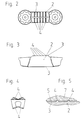
Figur 1- ein erfindungsgemäßes Schneidwerkzeug in Form eines Stechwerkzeuges in Schrägansicht
Figur 2- den Schneideinsatz für das Stechwerkzeug nach
Figur 1 in Draufsicht Figur 3- den Schneideinsatz nach
Figur 2 in Seitenansicht Figur 4- den Schneideinsatz nach den
Figuren 2 und 3 in Stirnansicht Figur 5- ein vergrößertes Detail der Seitenansicht der Berührungsflächen zwischen Werkzeughalter und Schneideinsatz des Stechwerkzeuges nach
Figur 1 im Schnitt
- Figure 1
- an inventive cutting tool in the form of a piercing tool in an oblique view
- Figure 2
- the cutting insert for the piercing tool according to Figure 1 in plan view
- Figure 3
- the cutting insert of Figure 2 in side view
- Figure 4
- the cutting insert according to Figures 2 and 3 in front view
- Figure 5
- an enlarged detail of the side view of the contact surfaces between the tool holder and cutting insert of the piercing tool according to Figure 1 in section
Figur 1 zeigt ein erfindungsgemäßes Stechwerkzeug, bestehend aus einem Werkzeughalter -1- und einem wendbaren Schneideinsatz -2- aus Hartmetall. Der klingenförmige vordere Abschnitt des Werkzeughalters -1- weist eine Ausnehmung zur Aufnahme des Schneideinsatzes -2- auf, die am Ende in einen Schlitz -9- übergeht. Dadurch wird ein starrer Stützabschnitt -6- und eine federnde Klemmpratze -7- gebildet. Beide Abschnitte -6- und -7- des Werkzeughalters -1- weisen konvexe V-förmige Kontakfflächen -5- zur Aufnahme des Schneideinsatzes auf. Die Oberfläche dieser Kontakfflächen -5-ist glatt ohne Ausnehmungen ausgeführt.
Wie auch in den Figuren 2, 3 und 4 zu erkennen ist, weist der Schneideinsatz - 2--entsprechend konkav geformte V-förmige Auflage- und Klemmflächen -3- auf. Sowohl die Auflagefläche -3- als auch die Klemmfläche -3- sind mit Elementen, das sind im Querschnitt dachförmig ausgeführte Erhebungen -4- quer zur Längsachse des Schneideinsatzes -2-, ausgeführt. Die Ergebungen -4- sind scharfkantig mit einem spitzen Winkel von 90° ausgeführt und weisen eine Höhe von etwa 0,08 mm, ausgehend von den Auflage- und Klemmflächen -3- auf.
Zur Klemmung des Schneideinsatzes -2- im Werkzeughalter -1- wird der Schneideinsatz -2- bis zum Anschlag in die Ausnehmung geschoben. Durch Verschrauben der Klemmschraube -8- mit dem Werkzeughalter -1- drückt die Klemmpratze -7- auf die Klemmfläche -3- des Schneideinsatzes -2- und damit die Auflagefläche -3- an die Kontakffläche -5- des Stützabschnittes -6-. Durch die Klemmkraft werden, wie in Figur 5 im Detail für die Kontakffläche -5- der Klemmpratze -7- und die Klemmfläche -3- des Schneideinsatzes -2- gezeigt, die Erhebungen -4- des Schneideinsatzes -2- in die Kontakfflächen -5- von Klemmpratze -7- und Stützabschnitt -6- hineingedrückt und verformen diese plastisch. Auf diese Weise entstehen in den Kontakfflächen -5- sichtbar ausgebildete V-förmige Nuten, die einerseits tief genug, sind den Schneideinsatz -2- gegen seitliche Kräfte sowie Zugkräfte aus der Ausnehmung heraus sicher zu stabilisieren und andererseits nur so tief sind, daß der Schneideinsatz nach Lösen der Klemmschraube -8- problemlos aus der Aufnahme enffernt werden kann.
Es ist darauf zu achten, daß beim erstmaligen Festklemmen des Schneideinsatzes -2- dieser bis zum Anschlag eingeschoben und damit richtig positioniert ist, um die Kerben in den Kontakfflächen -5- an den richtigen Stellen einzudrücken. Bei einem Wechsel des Schneideinsatzes -2- wird der neue durch die nunmehr in den Kontakfflächen -5- bereits vorhandenen Kerben automatisch richtig positioniert.Figure 1 shows a piercing tool according to the invention, consisting of a tool holder -1- and a reversible cutting insert -2- made of hard metal. The blade-shaped front section of the tool holder -1- has a recess for receiving the cutting insert -2-, which at the end merges into a slot -9-. This forms a rigid support section -6- and a resilient clamping claw -7-. Both sections -6- and -7- of the tool holder -1- have convex V-shaped contact surfaces -5- for receiving the cutting insert. The surface of these contact surfaces -5-is smooth without recesses.
As can also be seen in FIGS. 2, 3 and 4, the cutting insert - 2 - has correspondingly concave V-shaped support and clamping surfaces -3-. Both the contact surface -3- and the clamping surface -3- are made with elements, that is to say cross-sections of the cross-section of the cutting insert -2-, which are roof-shaped elevations. The results -4- are sharp-edged with an acute angle of 90 ° and have a height of approximately 0.08 mm, starting from the support and clamping surfaces -3-.
To clamp the cutting insert -2- in the tool holder -1-, the cutting insert -2- is pushed into the recess as far as it will go. By screwing the clamping screw -8- with the tool holder -1-, the clamping claw -7- presses on the clamping surface -3- of the cutting insert -2- and thus the contact surface -3- on the contact surface -5- of the support section -6-. As shown in FIG. 5 in detail for the contact surface -5- of the clamping claw -7- and the clamping surface -3- of the cutting insert -2-, the elevations -4- of the cutting insert -2- into the contact surfaces -5 - Pressed in by clamping claw -7- and support section -6- and deform them plastically. In this way, V-shaped grooves are formed in the contact surfaces -5-, which are deep enough on the one hand, the cutting insert -2- can be safely stabilized against lateral forces and tensile forces from the recess and on the other hand are only so deep that the cutting insert after loosening the clamping screw -8- can be easily removed from the holder.
It must be ensured that when the cutting insert -2- is clamped for the first time, it is pushed in as far as it will go and is therefore correct is positioned to press the notches in the contact surfaces -5- at the correct points. When the cutting insert -2- is changed, the new notches are automatically positioned correctly by the notches already existing in the contact surfaces -5-.
In einem Versuch zur Ermittlung der Auszugskraft der Wendeschneidplatten aus dem Werkzeughalter wurden zwei baugleiche Stechwerkzeuge einmal in der erfindungsgemäßen Ausführung mit Schneideinsätzen mit dachförmigen Erhebungen entsprechend der Figuren 2 bis 3 und einmal mit Schneideinsätzen mit glatten Klemm- und Auflageflächen auf einer Zugversuchsanlage miteinander verglichen.
Die einzelnen Wendeschneidplatten wurden jeweils in den Werkzeughaltern durch Festziehen der Klemmschrauben mit einem Anzugsmoment von 8 Nm festgeklemmt. Die Werkzeughalter wurden festgespannt und die jeweiligen Schneideinsätze mit einer Auszugsgeschwindigkeit von 1 mm/min aus dem Werkzeughalter gezogen.
Beim erfindungsgemäßen Schneidwerkzeug ergaben sich im Schnitt Auszugskräfte der Schneideinsätze aus dem Werkzeughalter von etwa 1350 N, während bei den Schneideinsätzen ohne dachförmige Erhebungen Auszugskräfte im Schnitt von etwa 700 N gemessen wurden. Durch die erfindungsgemäßen dachförmigen Erhebungen konnten die Auszugskräfte also nahezu auf den doppelten Wert erhöht werden.In an attempt to determine the pull-out force of the indexable inserts from the tool holder, two identical grooving tools were compared with one another in the embodiment according to the invention with cutting inserts with roof-shaped elevations according to FIGS. 2 to 3 and once with cutting inserts with smooth clamping and support surfaces on a tensile test system.
The individual indexable inserts were clamped in the tool holders by tightening the clamping screws with a tightening torque of 8 Nm. The tool holders were clamped and the respective cutting inserts were pulled out of the tool holder at a pull-out speed of 1 mm / min.
In the cutting tool according to the invention, pulling forces of the cutting inserts from the tool holder averaged about 1350 N, while pulling forces were measured on average of about 700 N for the cutting inserts without roof-shaped elevations. With the roof-shaped elevations according to the invention, the pull-out forces could thus be increased almost to twice the value.
Claims (4)
dadurch gekennzeichnet,
daß die Elemente (4) derart erhaben ausgebildet sind, daß durch die von der jeweiligen Klemmeinrichtung aufgebrachte Flächenpressung zur Fixierung der Schneideinsätze (2) eine plastische Verformung der Kontakfflächen am Werkzeughalter (1) erzeugt wird.Cutting tool with one or more interchangeable cutting inserts (2) which can be clamped onto the tool holder and have elements on the support and / or clamping surfaces (3) for a form-fitting, correct positioning.
characterized,
that the elements (4) are raised so that a plastic deformation of the contact surfaces on the tool holder (1) is generated by the surface pressure applied by the respective clamping device for fixing the cutting inserts (2).
Applications Claiming Priority (3)
| Application Number | Priority Date | Filing Date | Title |
|---|---|---|---|
| AT216/96 | 1996-04-18 | ||
| AT21696 | 1996-04-18 | ||
| AT0021696U AT1323U1 (en) | 1996-04-18 | 1996-04-18 | CUTTING TOOL WITH CLAMPING DEVICE |
Publications (2)
| Publication Number | Publication Date |
|---|---|
| EP0802006A1 true EP0802006A1 (en) | 1997-10-22 |
| EP0802006B1 EP0802006B1 (en) | 2000-07-12 |
Family
ID=3484608
Family Applications (1)
| Application Number | Title | Priority Date | Filing Date |
|---|---|---|---|
| EP97201086A Expired - Lifetime EP0802006B1 (en) | 1996-04-18 | 1997-04-11 | Cutting tool with clamping device |
Country Status (6)
| Country | Link |
|---|---|
| US (1) | US6261032B1 (en) |
| EP (1) | EP0802006B1 (en) |
| KR (1) | KR100489285B1 (en) |
| AT (2) | AT1323U1 (en) |
| DE (1) | DE59701994D1 (en) |
| ES (1) | ES2149542T3 (en) |
Cited By (5)
| Publication number | Priority date | Publication date | Assignee | Title |
|---|---|---|---|---|
| WO2000013824A1 (en) * | 1998-09-09 | 2000-03-16 | Sandvik Aktiebolag | Cutting insert for grooving operations |
| WO2001015839A1 (en) * | 1999-09-01 | 2001-03-08 | Mircona Ab | Method and holding device for a cutting tool |
| US6334742B1 (en) | 2000-02-28 | 2002-01-01 | Sandvik Inc. | Parting/grooving insert secured by friction in a holder |
| EP1743724A2 (en) | 2005-07-13 | 2007-01-17 | Fette GmbH | Method for producing a form-locking coupling between a tool insert and a tool insert holder on a rotating tool |
| EP3421159A1 (en) * | 2017-06-27 | 2019-01-02 | Walter Ag | Double ended cutting insert for parting |
Families Citing this family (25)
| Publication number | Priority date | Publication date | Assignee | Title |
|---|---|---|---|---|
| US6899493B1 (en) * | 1999-04-19 | 2005-05-31 | Jeffrey D. Russell | Cutting tool |
| US6712564B1 (en) * | 2000-09-29 | 2004-03-30 | Greenleaf Technology Corporation | Tool with improved resistance to displacement |
| DE10132721C1 (en) * | 2001-07-05 | 2003-01-23 | Horn P Hartmetall Werkzeugfab | cutter |
| US7140407B2 (en) * | 2004-02-17 | 2006-11-28 | Guofang Cao | Configurations and designs for stump grinding teeth and corresponding holding brackets |
| US7090585B2 (en) * | 2004-02-27 | 2006-08-15 | Kennametal Inc. | Nail manufacturing tool holder having a quick change mechanism |
| US20070237588A1 (en) * | 2006-03-24 | 2007-10-11 | Russell Jeffrey D | Cutting tool integral cooling groove |
| IL198407A (en) * | 2009-04-23 | 2014-01-30 | Iscar Ltd | Cutting tool and cutting insert |
| KR101105058B1 (en) * | 2009-05-07 | 2012-01-13 | 대구텍 유한회사 | Cutting tool and insert for cutting tool |
| DE202011110268U1 (en) | 2010-08-04 | 2013-04-24 | Ceramtec Gmbh | Cutting tool for grooving and grooving |
| US9517509B2 (en) * | 2010-12-25 | 2016-12-13 | Kyocera Corporation | Cutting tool and method of manufacturing machined product using the same |
| US8388268B2 (en) | 2011-03-07 | 2013-03-05 | Kennametal Inc. | Cutting assembly |
| JP2014147977A (en) * | 2011-05-23 | 2014-08-21 | Tungaloy Corp | Cutting insert, and cutting tool using cutting insert |
| US8827598B2 (en) | 2011-11-22 | 2014-09-09 | Kennametal Inc. | Cutting assembly with enhanced coolant delivery |
| DE102012004804C5 (en) | 2012-03-09 | 2019-03-14 | Kennametal Inc. | Puncture cutting plate and lancing cutting tool |
| US9579727B2 (en) | 2014-05-28 | 2017-02-28 | Kennametal Inc. | Cutting assembly with cutting insert having enhanced coolant delivery |
| US20160016233A1 (en) * | 2014-07-17 | 2016-01-21 | Kennametal India Limited | Notched cutting inserts and applications thereof |
| DE102014116660A1 (en) * | 2014-11-14 | 2016-05-19 | Kennametal Inc. | cutting insert |
| US10384268B1 (en) | 2018-02-05 | 2019-08-20 | Iscar, Ltd. | Grooving insert having rearwardly pointing arrowhead-shaped chip former |
| US11806793B2 (en) | 2021-11-03 | 2023-11-07 | Iscar, Ltd. | Cutting insert having laterally spaced apart, longitudinally extending wedge abutment surfaces, tool holder and cutting tool |
| US11766724B1 (en) | 2022-03-16 | 2023-09-26 | Iscar, Ltd. | Cutting tool and tool holder having separate rear abutment and wedged rear stopper surfaces |
| US12172219B2 (en) | 2022-03-16 | 2024-12-24 | Iscar, Ltd. | Cutting insert having grooved top and bottom abutment surfaces with inner and outer pairs of wedge angles, and cutting tool |
| US12275078B2 (en) | 2022-05-03 | 2025-04-15 | Iscar, Ltd. | Rotationally asymmetric double-ended grooving cutting insert, insert holder and cutting tool |
| US11904393B1 (en) | 2022-08-18 | 2024-02-20 | Iscar, Ltd. | External grooving insert holder having upper and lower jaws connected by angled hinge portion with cooling channel extending through hinge portion, and cutting tool |
| US12465981B2 (en) | 2022-09-07 | 2025-11-11 | Iscar, Ltd. | Cemented carbide cutting insert for parting metal workpieces |
| US12434306B2 (en) | 2022-10-25 | 2025-10-07 | Taegutec Ltd. | Cutting tool assembly |
Citations (4)
| Publication number | Priority date | Publication date | Assignee | Title |
|---|---|---|---|---|
| DE1270924B (en) * | 1964-06-25 | 1968-06-20 | Karl Hertel | Chip-removing tool with the cutting body clamped in a receiving groove |
| EP0291933A1 (en) * | 1987-05-20 | 1988-11-23 | Sumitomo Electric Industries Limited | Cutting tool |
| US5211516A (en) * | 1990-10-29 | 1993-05-18 | Mapal Fabrik Fur Prazisionswerkzeuge Dr. Kress Kg | Cutting tool |
| WO1995029026A1 (en) * | 1994-04-27 | 1995-11-02 | Sandvik Ab | Tool holder for inserts, including a ribbed clamping surface |
Family Cites Families (14)
| Publication number | Priority date | Publication date | Assignee | Title |
|---|---|---|---|---|
| US1793564A (en) * | 1927-06-08 | 1931-02-24 | O K Tool Co Inc | Tool holder with dovetail lock |
| FR764093A (en) * | 1933-11-21 | 1934-05-14 | Adjustable flexure tool holder | |
| US2930111A (en) * | 1954-02-26 | 1960-03-29 | Adamas Carbide Corp | Tool holder |
| DE1084106B (en) * | 1954-10-14 | 1960-06-23 | Robert Breuning | Carbide cutting plate for turning tools or the like. |
| DE1037807B (en) * | 1957-02-01 | 1958-08-28 | Gustav Heldmann | Clamping device for cutting tools |
| US3124864A (en) * | 1960-10-05 | 1964-03-17 | frommelt etal | |
| US3662444A (en) | 1970-03-09 | 1972-05-16 | Ingersoll Milling Machine Co | Indexable cutting insert and holder therefor |
| IL48613A0 (en) | 1975-12-08 | 1976-02-29 | Iscar Ltd | Cutting tool providing mounting for interchangeable cutting inserts |
| DE3617119A1 (en) | 1986-05-22 | 1987-11-26 | Gte Valeron Corp | Adjustable indexable insert |
| NL8902275A (en) * | 1989-09-12 | 1991-04-02 | Duracarb Bv | CHISEL HOLDER AND CHISEL OF A CUTTING MACHINE. |
| DE9201113U1 (en) | 1992-01-30 | 1993-02-25 | Deitert, Heinz, 4836 Herzebrock-Clarholz | Cutting plate |
| SE505488C2 (en) | 1992-04-28 | 1997-09-08 | Sandvik Ab | Cut-off tools or similar operations |
| DE4415425A1 (en) | 1994-05-03 | 1995-11-09 | Krupp Widia Gmbh | Cutting tool |
| IL112818A (en) * | 1995-02-28 | 1999-10-28 | Iscar Ltd | Tool holder having a grooved seat |
-
1996
- 1996-04-18 AT AT0021696U patent/AT1323U1/en not_active IP Right Cessation
-
1997
- 1997-04-02 KR KR1019970012196A patent/KR100489285B1/en not_active Expired - Fee Related
- 1997-04-08 US US08/826,929 patent/US6261032B1/en not_active Expired - Lifetime
- 1997-04-11 AT AT97201086T patent/ATE194532T1/en active
- 1997-04-11 EP EP97201086A patent/EP0802006B1/en not_active Expired - Lifetime
- 1997-04-11 ES ES97201086T patent/ES2149542T3/en not_active Expired - Lifetime
- 1997-04-11 DE DE59701994T patent/DE59701994D1/en not_active Expired - Lifetime
Patent Citations (4)
| Publication number | Priority date | Publication date | Assignee | Title |
|---|---|---|---|---|
| DE1270924B (en) * | 1964-06-25 | 1968-06-20 | Karl Hertel | Chip-removing tool with the cutting body clamped in a receiving groove |
| EP0291933A1 (en) * | 1987-05-20 | 1988-11-23 | Sumitomo Electric Industries Limited | Cutting tool |
| US5211516A (en) * | 1990-10-29 | 1993-05-18 | Mapal Fabrik Fur Prazisionswerkzeuge Dr. Kress Kg | Cutting tool |
| WO1995029026A1 (en) * | 1994-04-27 | 1995-11-02 | Sandvik Ab | Tool holder for inserts, including a ribbed clamping surface |
Cited By (13)
| Publication number | Priority date | Publication date | Assignee | Title |
|---|---|---|---|---|
| KR100676950B1 (en) * | 1998-09-09 | 2007-01-31 | 산드빅 인터렉츄얼 프로퍼티 에이비 | Cutting inserts for grooving |
| CN1115219C (en) * | 1998-09-09 | 2003-07-23 | 桑德维克公司 | Cutting insert for grooving operations |
| WO2000013824A1 (en) * | 1998-09-09 | 2000-03-16 | Sandvik Aktiebolag | Cutting insert for grooving operations |
| JP2009056594A (en) * | 1998-09-09 | 2009-03-19 | Sandvik Intellectual Property Ab | Cutting insert for groove-cutting work |
| WO2001015839A1 (en) * | 1999-09-01 | 2001-03-08 | Mircona Ab | Method and holding device for a cutting tool |
| US6758638B1 (en) | 1999-09-01 | 2004-07-06 | Mircona Ab | Method and holding device for a cutting tool |
| KR100830284B1 (en) * | 1999-09-01 | 2008-05-19 | 미르코나 에이비이 | Method and holding device for a cutting tool |
| HRP20020188B1 (en) * | 1999-09-01 | 2009-05-31 | Mircona Ab | Method and holding device for a cutting tool |
| US6334742B1 (en) | 2000-02-28 | 2002-01-01 | Sandvik Inc. | Parting/grooving insert secured by friction in a holder |
| EP1743724A2 (en) | 2005-07-13 | 2007-01-17 | Fette GmbH | Method for producing a form-locking coupling between a tool insert and a tool insert holder on a rotating tool |
| EP1743724A3 (en) * | 2005-07-13 | 2008-07-09 | Fette GmbH | Method for producing a form-locking coupling between a tool insert and a tool insert holder on a rotating tool |
| US7490533B2 (en) | 2005-07-13 | 2009-02-17 | Fette Gmbh | Method for making a form-fitting connection between a tool insert and a tool holder of a rotating tool |
| EP3421159A1 (en) * | 2017-06-27 | 2019-01-02 | Walter Ag | Double ended cutting insert for parting |
Also Published As
| Publication number | Publication date |
|---|---|
| EP0802006B1 (en) | 2000-07-12 |
| KR970069202A (en) | 1997-11-07 |
| KR100489285B1 (en) | 2005-10-05 |
| ATE194532T1 (en) | 2000-07-15 |
| DE59701994D1 (en) | 2000-08-17 |
| US6261032B1 (en) | 2001-07-17 |
| AT1323U1 (en) | 1997-03-25 |
| ES2149542T3 (en) | 2000-11-01 |
Similar Documents
| Publication | Publication Date | Title |
|---|---|---|
| EP0802006B1 (en) | Cutting tool with clamping device | |
| DE69802998T2 (en) | Grooving and parting tool | |
| DE69208474T2 (en) | SAW BLADE | |
| DE69608965T2 (en) | CUTTING TOOL WITH INSERT CLAMPING DEVICE | |
| DE19736485C2 (en) | Ball nose end mill with interchangeable cutting tip | |
| WO1988001920A1 (en) | Metal cutting tool for machining with chip removal, such as chamfering, piercing, facing and milling | |
| DE202005016610U1 (en) | Reversible plate for tool, has body, on which supporting slots are pressed, such that transitions between their side surfaces and surfaces adjacent to side surfaces are rounded, and side surfaces are curved by slots` cross sectional shape | |
| EP2136947B1 (en) | Indexable cutting insert | |
| DE60301887T2 (en) | CUTTING TOOL HEAD FOR A METAL MACHINING TOOL | |
| EP0666785B1 (en) | Metal removing tool, in particular lancing insert | |
| EP1713604B1 (en) | Cutting insert and tool for using the same | |
| DE69923362T2 (en) | Tool for machining | |
| EP0559965B1 (en) | Form tool | |
| DE69213053T2 (en) | Cutting tool for a peeling operation | |
| DE2542346C3 (en) | Internal broaching tool, in particular for producing profile grooves | |
| DE4413687A1 (en) | Jaw arrangement for a chuck | |
| WO1992016327A1 (en) | Sawing or milling tool with blade-shaped tool body | |
| EP0804986A1 (en) | Cutting element | |
| EP0285704A2 (en) | Clamping system of several parts in particular for concentric running tools | |
| DE60016935T2 (en) | METHOD FOR TIGHTENING A CUTTING INSERT, CUTTING INSERT AND CUTTING TOOL | |
| DE19849445A1 (en) | Tool holder for a machine tool | |
| DE3828482C2 (en) | Pushing or pulling tool | |
| DE4310565C2 (en) | Cutting tool with insert and insert holder | |
| DE1295967B (en) | Cutting tool with exchangeable cutting body | |
| DE3219674A1 (en) | COLD ROLLING TOOL AND METHOD FOR PRODUCING IT |
Legal Events
| Date | Code | Title | Description |
|---|---|---|---|
| PUAI | Public reference made under article 153(3) epc to a published international application that has entered the european phase |
Free format text: ORIGINAL CODE: 0009012 |
|
| 17P | Request for examination filed |
Effective date: 19970821 |
|
| AK | Designated contracting states |
Kind code of ref document: A1 Designated state(s): AT CH DE ES FR GB IT LI NL SE |
|
| GRAG | Despatch of communication of intention to grant |
Free format text: ORIGINAL CODE: EPIDOS AGRA |
|
| GRAG | Despatch of communication of intention to grant |
Free format text: ORIGINAL CODE: EPIDOS AGRA |
|
| GRAH | Despatch of communication of intention to grant a patent |
Free format text: ORIGINAL CODE: EPIDOS IGRA |
|
| 17Q | First examination report despatched |
Effective date: 19990802 |
|
| GRAH | Despatch of communication of intention to grant a patent |
Free format text: ORIGINAL CODE: EPIDOS IGRA |
|
| RAP1 | Party data changed (applicant data changed or rights of an application transferred) |
Owner name: PLANSEE TIZIT AKTIENGESELLSCHAFT |
|
| GRAA | (expected) grant |
Free format text: ORIGINAL CODE: 0009210 |
|
| AK | Designated contracting states |
Kind code of ref document: B1 Designated state(s): AT CH DE ES FR GB IT LI NL SE |
|
| REF | Corresponds to: |
Ref document number: 194532 Country of ref document: AT Date of ref document: 20000715 Kind code of ref document: T |
|
| ITF | It: translation for a ep patent filed | ||
| REG | Reference to a national code |
Ref country code: CH Ref legal event code: EP |
|
| GBT | Gb: translation of ep patent filed (gb section 77(6)(a)/1977) |
Effective date: 20000712 |
|
| REF | Corresponds to: |
Ref document number: 59701994 Country of ref document: DE Date of ref document: 20000817 |
|
| REG | Reference to a national code |
Ref country code: ES Ref legal event code: FG2A Ref document number: 2149542 Country of ref document: ES Kind code of ref document: T3 |
|
| ET | Fr: translation filed | ||
| PLBQ | Unpublished change to opponent data |
Free format text: ORIGINAL CODE: EPIDOS OPPO |
|
| PLBI | Opposition filed |
Free format text: ORIGINAL CODE: 0009260 |
|
| 26 | Opposition filed |
Opponent name: SANDVIK AB Effective date: 20010411 |
|
| PLBQ | Unpublished change to opponent data |
Free format text: ORIGINAL CODE: EPIDOS OPPO |
|
| PLAB | Opposition data, opponent's data or that of the opponent's representative modified |
Free format text: ORIGINAL CODE: 0009299OPPO |
|
| NLR1 | Nl: opposition has been filed with the epo |
Opponent name: SANDVIK AB |
|
| D26 | Opposition filed (deleted) | ||
| PLBE | No opposition filed within time limit |
Free format text: ORIGINAL CODE: 0009261 |
|
| STAA | Information on the status of an ep patent application or granted ep patent |
Free format text: STATUS: NO OPPOSITION FILED WITHIN TIME LIMIT |
|
| REG | Reference to a national code |
Ref country code: GB Ref legal event code: IF02 |
|
| 26N | No opposition filed | ||
| REG | Reference to a national code |
Ref country code: DE Ref legal event code: R082 Ref document number: 59701994 Country of ref document: DE Effective date: 20120919 Ref country code: DE Ref legal event code: R081 Ref document number: 59701994 Country of ref document: DE Owner name: CERATIZIT AUSTRIA GESELLSCHAFT M.B.H., AT Free format text: FORMER OWNER: PLANSEE TIZIT AG, REUTTE, AT Effective date: 20120813 |
|
| REG | Reference to a national code |
Ref country code: AT Ref legal event code: HC Ref document number: 194532 Country of ref document: AT Kind code of ref document: T Owner name: CERATIZIT AUSTRIA GESELLSCHAFT M.B.H., AT Effective date: 20121003 |
|
| REG | Reference to a national code |
Ref country code: FR Ref legal event code: PLFP Year of fee payment: 20 |
|
| PGFP | Annual fee paid to national office [announced via postgrant information from national office to epo] |
Ref country code: NL Payment date: 20160420 Year of fee payment: 20 |
|
| PGFP | Annual fee paid to national office [announced via postgrant information from national office to epo] |
Ref country code: ES Payment date: 20160413 Year of fee payment: 20 Ref country code: GB Payment date: 20160421 Year of fee payment: 20 Ref country code: CH Payment date: 20160420 Year of fee payment: 20 Ref country code: DE Payment date: 20160421 Year of fee payment: 20 |
|
| PGFP | Annual fee paid to national office [announced via postgrant information from national office to epo] |
Ref country code: FR Payment date: 20160421 Year of fee payment: 20 Ref country code: SE Payment date: 20160420 Year of fee payment: 20 Ref country code: IT Payment date: 20160427 Year of fee payment: 20 Ref country code: AT Payment date: 20160421 Year of fee payment: 20 |
|
| REG | Reference to a national code |
Ref country code: DE Ref legal event code: R071 Ref document number: 59701994 Country of ref document: DE |
|
| REG | Reference to a national code |
Ref country code: NL Ref legal event code: MK Effective date: 20170410 |
|
| REG | Reference to a national code |
Ref country code: CH Ref legal event code: PL |
|
| REG | Reference to a national code |
Ref country code: GB Ref legal event code: PE20 Expiry date: 20170410 |
|
| REG | Reference to a national code |
Ref country code: AT Ref legal event code: MK07 Ref document number: 194532 Country of ref document: AT Kind code of ref document: T Effective date: 20170411 |
|
| PG25 | Lapsed in a contracting state [announced via postgrant information from national office to epo] |
Ref country code: GB Free format text: LAPSE BECAUSE OF EXPIRATION OF PROTECTION Effective date: 20170410 |
|
| REG | Reference to a national code |
Ref country code: ES Ref legal event code: FD2A Effective date: 20180508 |
|
| PG25 | Lapsed in a contracting state [announced via postgrant information from national office to epo] |
Ref country code: ES Free format text: LAPSE BECAUSE OF EXPIRATION OF PROTECTION Effective date: 20170412 |