EP0801820B1 - An antenna for a portable radio communication device - Google Patents
An antenna for a portable radio communication device Download PDFInfo
- Publication number
- EP0801820B1 EP0801820B1 EP96900071A EP96900071A EP0801820B1 EP 0801820 B1 EP0801820 B1 EP 0801820B1 EP 96900071 A EP96900071 A EP 96900071A EP 96900071 A EP96900071 A EP 96900071A EP 0801820 B1 EP0801820 B1 EP 0801820B1
- Authority
- EP
- European Patent Office
- Prior art keywords
- antenna
- radiation
- electrically conductive
- conductive member
- radio communication
- Prior art date
- Legal status (The legal status is an assumption and is not a legal conclusion. Google has not performed a legal analysis and makes no representation as to the accuracy of the status listed.)
- Expired - Lifetime
Links
Images


Classifications
-
- H—ELECTRICITY
- H01—ELECTRIC ELEMENTS
- H01Q—ANTENNAS, i.e. RADIO AERIALS
- H01Q1/00—Details of, or arrangements associated with, antennas
- H01Q1/12—Supports; Mounting means
- H01Q1/22—Supports; Mounting means by structural association with other equipment or articles
- H01Q1/24—Supports; Mounting means by structural association with other equipment or articles with receiving set
- H01Q1/241—Supports; Mounting means by structural association with other equipment or articles with receiving set used in mobile communications, e.g. GSM
- H01Q1/242—Supports; Mounting means by structural association with other equipment or articles with receiving set used in mobile communications, e.g. GSM specially adapted for hand-held use
- H01Q1/245—Supports; Mounting means by structural association with other equipment or articles with receiving set used in mobile communications, e.g. GSM specially adapted for hand-held use with means for shaping the antenna pattern, e.g. in order to protect user against rf exposure
-
- H—ELECTRICITY
- H01—ELECTRIC ELEMENTS
- H01Q—ANTENNAS, i.e. RADIO AERIALS
- H01Q19/00—Combinations of primary active antenna elements and units with secondary devices, e.g. with quasi-optical devices, for giving the antenna a desired directional characteristic
- H01Q19/06—Combinations of primary active antenna elements and units with secondary devices, e.g. with quasi-optical devices, for giving the antenna a desired directional characteristic using refracting or diffracting devices, e.g. lens
- H01Q19/09—Combinations of primary active antenna elements and units with secondary devices, e.g. with quasi-optical devices, for giving the antenna a desired directional characteristic using refracting or diffracting devices, e.g. lens wherein the primary active element is coated with or embedded in a dielectric or magnetic material
Definitions
- the present invention concerns radiation reduction apparatus of a type intended to be used in conjunction with hand-held or otherwise portable radio phones and the like to reduce, re-direct, or redistribute away from a user or other radiation dissipative medium radiation emitted from the radiation emitting structure of the phone, such as the antenna.
- Cellular and other portable radio telephones typically have antennas which extend from the housing of the phone. While the phone is in use the antenna emits radiation which has caused concern among the medical community as to the radiation's effects on the user of the phone.
- United States Patent No. 3,039,001 discloses that a sheet of vinyl or other plastic material containing resin, plasticizer and stabilizer may have a protective material such as pulverized lead uniformly distributed therethrough in order to provide a flexible sheet of material which protects the wearer against X-rays, Gamma rays. Neutron rays, secondary cosmic rays and the like.
- United States Patent No. 5,012,114 discloses a gamma radiation shield which comprises a wrappable sheet of gamma radiation shielding material to which is affixed releasable contact-fasteners, which are so dimensioned and configured that when a shield member is wrapped around a gamma radiation emitting structure, complimentary locking portions of the releasable fasteners engage each other to securely hold the shield member in shielding position wrapped around the structure.
- the gamma radiation shielding material may be comprised of the known construction of fine lead powder being uniformly dispersed in a matrix of thermo-plastic material which serves as a binder for the lead powder so as to form a flexible sheet.
- the releasable contact-fasteners may be of a type sold under the trade-mark Velcro.
- the patent is directed to protecting personnel in nuclear reactors and the like by shielding conduits such as pipes, most clearly seen in Figure 6 of the patent, through which radioactive material flows.
- electromagnetic shielding to minimize interference between electromagnetic signals radiated by cellular phones and like electronic equipment with another portion of that equipment and the minimization of such interference by interposing electrically conducting material in the form of a shield between the source of the electromagnetic signals and the circuitry subject to interference is taught by United States Patent No. 5,124,889 entitled "Electromagnetic Shielding Apparatus for Cellular Phones".
- the reference to electromagnetic shielding does not appear to be concerned with protecting the user of the electronic device from radiation from the antenna or the like.
- radio waves that carry the call emanate directly from the telephone, specifically the length of the telephone and antenna, most intensely at a midpoint there along, while the telephone is held to the ear of the user.
- radio frequency waves entering the dissipative medium of the user's head may cause heating, cancer or DNA fragmentation.
- the "Cellguard” device consists of two sections of molded plastic, each with metal inside, that serves to block or deflect the radio frequency signal. One part of the device covers the phone's antenna and the other part fits over the earpiece of the phone. The metal of the Cellguard device is placed between the antenna and the user and between the earpiece and the user.
- a similar device that is, an arrangement in which a radiation shielding device is placed between the antenna and the user is taught in U.S. Patent No. 5,335,366 which issued to Daniels on August 2, 1994.
- Daniels discloses a radiation shielding apparatus for a radio transmitting device having a radiation shield disposed between the antenna and a user, the radiation shield for absorbing, blocking and/or reflecting electromagnetic wave radiation.
- United States Patent No. 5,336,896 which issued to Katz on August 9, 1994 for a cellular telephone users protective device teaches a cellular telephone accessory both for protecting a user from electromagnetic radiation and for providing a handle for the cellular phone.
- a tilt and swivel base is taught to permit moving the cellular phone antenna away from close contact with the user's head and to also supply a carrying handle.
- What is further taught is providing a protective magnetic radiation shielded jacket to contain the cellular phone within the jacket, the antenna tilt and swivel base attached to the outside of the jacket.
- the present invention has at least five objects.
- the first object in one embodiment, is to reduce the overall amount of electromagnetic radiation emitted by reducing the emitted power of the antenna.
- the second object in a further embodiment, is to redistribute the radiation in the vicinity of the phone and in particular the antenna, ie. in the near field, away from an associated dissipative medium such as the head of a user.
- the present invention changes the near field radiation pattern surrounding a radio communication device such as a radio phone, and in particular surrounding the device's antenna so that: (a) a reduction is attained in radiation field strength during transmission thereby reducing "hot spots" at the associated dissipative medium such as the user's head; (b) a reduction is attained in the amount of radiated energy during transmission which is absorbed by the associated dissipative medium, to thereby increase the effective power of the radio transmission; and, (c) an increase is attained in the effectiveness of the antenna during reception of radio transmissions by an increase in the effective exposure of the antenna.
- the third object is to accomplish the above objects without significantly adversely affecting the operation of a radio communication device such as a cellular telephone within a cellular telephone communication system, which adverse operation may result if the antenna excessively loses radiating power or becomes excessively directional.
- a radio communication device such as a cellular telephone within a cellular telephone communication system
- the far field radiation pattern does not have large signal strength variations with the direction in which the signal is sent. It is desired that the user can hold the cellular telephone in a random orientation without concern about the direction in which the signal must travel in order to reach the center of the cell. Modification of an antenna can result in large changes to the far field radiation pattern.
- the fourth object is to avoid damage or undue strain on the internal electrical circuitry of the cellular phone. Such damage is conceivable in a situation where a modification to the antenna results in a greater electrical load being placed on the electrical circuitry so that a greater current flows through parts of the cellular phone. If this increased current exceeds the limits contemplated by the designers of the cellular phone, some internal parts of the cellular phone could have their operation impaired or could malfunction.
- the fifth object is to maintain operation of the receiving function of the cellular telephone to an acceptable degree.
- the antenna of the cellular telephone simultaneously operates with two functions. One is to transmit signals, and it is this function that results in high intensity radiation being present in the vicinity of the cellular telephone.
- the second function of the antenna is to receive signals from a distant source, convert these signals into oscillating electrical currents which are converted by the circuitry of the cellular telephone into a voice message heard by the user. It is conceivable that modifications to the antenna could decrease the ability of the cellular phone to clearly receive these incoming signals. It is an object of the present invention to not cause unacceptable reduction in the quality of these incoming signals, but in fact to increase the reception quality, by increasing the effective exposure of the antenna.
- the present invention provides an improved antenna for portable radio communication device which includes, a first elongate electrically conductive member having opposed first and second ends, where the first end is adapted to be mounted in electrica communication to a radio communication device, whereby when the first elongate electrically conductive member is mounted in electrical communication to a radio communication device, a radiation field pattern is generated by radiation emitted by the first elongate electrically conductive member and the radio communication device during radio transmission, the radiation field pattern having maximum intensity at a first location, the device also including means for increasing radiation resistance of the first elongate electrically conductive member mounted at an optimized position at generally the second end, whereby, when the means for increasing radiation resistance is mounted to the first elongate electrically conductive member at the optimized position at generally the second end and the first elongate electrically conductive member is mounted in electrical communication to a radio communication device, during radio transmission the radiation field pattern maximum intensity is shifted from the first location to a second location closer to the second end, and near field intensity of the radiation field pattern at the
- the short parasitic element to a helical electrically conductive coil.
- the helical electrically conductive coil may be mounted over the second end to thereby journal the second end within a cavity within the helical electrically conductive coil at least partially along the cavity so as to optimize antenna performance by reducing near field radiation intensity at the first location without substantially adversely affecting far field performance.
- the short parasitic element may be a short second elongate electrically conductive member mounted generally adjacent and parallel to the first elongate electrically conductive member.
- the antenna may be a monopole antenna.
- the radio communication device radiation has a range of operational wavelengths corresponding to the operational bandwidth and the short parasitic element may have a length of less than approximately three-quarters of one-half of a wavelength, more especially no greater than one-half of a wavelength, within the range of operational wavelengths.
- the short parasitic element may advantageously have a length of approximately 1/20th of a wavelength within the range of operational wavelengths.
- the short parasitic element may be a short length of dielectric material mounted generally adjacent and parallel to the first electrically conductive member.
- the dielectric material is an inert matrix impregnated with heavy metal, where the heavy metal may be heavy metal powder, and where the inert matrix may be flexible.
- the inert matrix impregnated with heavy metal may be lead vinyl.
- the short parasitic element may be tilted relative to the longitudinal axis of the antenna, whereby, because of the directional characteristics of the short parasitic element, tilting the longitudinal axis of the short parasitic element towards the dissipative medium at the first location may accomplish a further reduction in near field radiation intensity at the first location.
- Figures 1 (a), 1 (b) and 1 (c) are, respectively, an exploded perspective view of the Cellguard device, a fragmentary partially cut away view of the base of the Cellguard antenna cover, and a reverse perspective view of the Cellguard earpiece cover.
- Figures 1 (c) and 1 (d) are schematic views of the operation of a prior art radio communication device antenna.
- Figure 2 is a cross-sectional view along lines 2 - 2 in Figure 3 illustrating a time averaged near field radiation pattern.
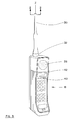
- Figure 3 is, in perspective view, a radio communication device incorporating a radiation reduction apparatus.
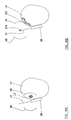
- Figure 4a is a diagram illustrating the radiation pattern associated with prior art hand held portable communication devices.
- Figure 4b is the diagram of Figure 4a illustrating a redistributed radiation field associated with the improved antenna of the present invention.
- Figure 5a is a front elevation view of a cellular telephone having an improved antenna of the present invention.
- Figure 5b is the cellular telephone of Figure 5a with the antenna casing partially cut away.
- Figure 5c is a side elevation view of a further embodiment of a cellular telephone having a retractable improved antenna according to the internal construction of Figure 5b.
- Figure 5d is a side elevation view of a cellular phone with its antenna shown in cross-section to illustrate a length or dielectric material mounted along the antenna.
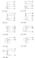
- Figures 6 (a) - 6 (e) and 6 (i) schematically illustrate alternative embodiments of the improved antenna of the present invention for reducing antenna power.
- Figures 6 (f) - 6 (h) schematically illustrate adjustable antenna power reduction means.
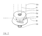
- Figure 7 is an enlarged perspective view of an antenna insert embodiment incorporating one aspect of the present invention.
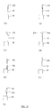
- Figures 8 (a) - 8 (i) illustrate alternative embodiments of short parasitic elements incorporated in the present invention.
- Figure 9 is a front elevation view of a conventional antenna having a helical wire coil SPE mounted thereon.
- Figures 10 (a) - 10 (e) illustrate alternative embodiments of parasitically top-loaded antennas.
- the Cellguard Device The Cellguard Device:
- the Cellguard device exists in the prior art. It is depicted in Figures 1 (a) - 1 (c). Testing of the flexible metal alloy strip of the Cellguard device indicates that it is likely a carbon steel alloy mostly comprised of chromium and iron. As may be seen, the geometric shape of the metal alloy strip combined with the flexible properties of the alloy, allow the alloy strip to be flexed, although repeated flexing, it has been found, results in fatigue and eventual failure of the alloy along the centre line of the alloy strip where the alloy is narrowest by design to accommodate the flexing of the alloy strip.
- the base of the alloy strip electrically connects to a metal tab extending substantially vertically from the earpiece covering portion of the Cellguard device.
- the base of the alloy strip and the metal tab are electrically connected, once installed on a cellular phone, to the casing of the cellular phone by metal-to-metal contact with the metal base of the antenna (not shown).
- the metal tab may be seen protruding vertically from the earpiece cover in Figure 1 (a) and may also be seen protruding vertically upwards through the antenna receiving hole in the earpiece cover as depicted in Figure 1 (c).
- the metal alloy strip depicted in Figure 1 (a) is encased in a urethane plastic moulding along the flat side of the moulding shown in Figure 1 (a) and better seen in perspective partial cut-away view of Figure 1 (b).
- the Cellguard device relies on a conventional method of shielding, namely, the electrical grounding of conductive shielding material placed alongside a radiation source between the radiation source and the object to be shielded.
- Figure 1(d) illustrates the physical arrangement of the cellular telephone. Note that only the circuitry that transmits the signal from the portable cellular telephone to the cell centre is shown. The entire circuitry of the cellular telephone is represented by a single device conventionally called a radio frequency (RF) oscillator. This RF oscillator generates an alternating voltage at a frequency between 800 and 900 megahertz. One terminal of the RF oscillator is electrically connected to the chassis of the cellular telephone. The other terminal of the RF oscillator is attached to a length of wire which forms the antenna.
- RF radio frequency
- the antenna and the conductive elements electrically connected to the RF oscillator act as an "antenna" so that the entire telephone, in this case the antenna and the chassis, radiate radiation. Because the radiation field is strongest at approximately the mid-point of the overall radiating body, the maximum radiation intensity will be at approximately where the cellular phone is held closest to the head of the user.
- the alternating voltage from the RF oscillator forces alternating current to flow in the antenna. This current creates electric and magnetic fields in the air surrounding the antenna. These electric and magnetic fields oscillate at the same frequency, between 800 and 900 megahertz.
- oscillations ripple outwards like waves on a pond surface, and carry the signal to the distant antenna at the centre of the cell, except where they are absorbed by the dissipative medium associated with the operation of a cellular phone, namely, the ear, skull, brain etc. of the user.
- dissipative medium associated with a radio communication device will depend on the particular application of the device.
- One example is the cellular telephone where health hazards have been identified with the intense near field radiation strongest near the base of the antenna, which is emitted by the cellular phone and which causes hot spots in the user's head (where a "hot spot" is a reference to the heating of the dissipative medium where the radiation from the antenna is being absorbed).
- Another example of a dissipative medium associated with a radio communication device may be that of an antenna mounted in proximity to a dissipative medium such as radiation absorbing material used for current radar defeating technology.
- Figure 1(e) schematically depicts the cellular telephone of figure 1(d), modified to schematically illustrate the electrical properties of the circuit.
- the antenna has three kinds of electrical properties. The first is inductance, which is the characteristic of maintaining a current in a wire once the current is flowing. The second is capacitance, which is the characteristic of building up a stored charge in an electrical component when voltage is applied. The third is resistance, which is the ratio of the voltage applied across a conducting material to the current flowing through the conducting material.
- the antenna together with the circuitry inside the cellular telephone, has inductance, and the value of this inductance is represented by the symbol L ant , and is understood to be expressed as a number of Henries.
- the antenna together with circuitry inside the cellular telephone, has capacitance, and the value of this capacitance is represented by the symbol C ant , and is understood to be expressed as a number of Farads.
- the antenna considered as a piece of wire, has an electrical resistance, expressed by the symbol R ant , and is understood to be expressed as a number of Ohms.
- the internal circuitry of the cellular telephone has some resistance, which is expressed by the symbol R tel .
- the antenna has an extra resistance due to the creation of radio waves by the motion of currents in the antenna, and this is expressed by the symbol R rad . This last resistance is conventionally called radiation resistance.
- the RF oscillator inside the cellular telephone generates a voltage that oscillates with time.
- the symbol ⁇ tel represents this voltage, and is measured in volts. The actual voltage varies with time.
- the maximum is ⁇ tel and the minimum is - ⁇ tel .
- the root mean squared (rms) voltage supplied is therefore 0.70711 ⁇ tel .
- the frequency of the oscillation is represented by the symbol f , and is understood to be measured in Hertz.
- the value of f varies, depending on the cellular phone channel being used, but is in the range from 800,000,000 Hertz to 900,000,000 Hertz, that is, from 800 MHz to 900 MHz.
- the voltage from the RF oscillator is a function of time, where t stands for time in seconds.
- the voltage applied at a given instant of time, t is represented by the notation ⁇ ( t ).
- I(t) I ant cos((2 ⁇ ft) - ⁇ ) where the symbol ⁇ (phi) is called the phase angle of the current, and is measured in radians.
- I ant ⁇ tel / ⁇ [(R ant + R rad + R tel ) 2 + (2 ⁇ fL ant -1/(2 ⁇ fC ant )) 2 ]
- the next quantity to consider is the power being radiated by the antenna.
- Power is energy per unit time, and is measured in Watts.
- the power emitted by a handheld cellular telephone can vary, but is generally less than 0.6 Watts.
- One of the objects of the present invention is to reduce the output or emitted power. P.
- the above equation shows that this can be accomplished either by decreasing the antenna current, I ant , or by increasing the radiation resistance, R rad , or both, or by some combined variation of I ant and R rad where either I ant increases or R rad decreases so long as the overall effect on P is a decrease.
- Charge is a property of matter associated with the creation of electric and magnetic fields around matter and forces upon material objects in the presence of electric and magnetic fields.
- the distribution of charge as a function of position and time is mathematically represented by the charge density function, which is denoted by the symbol p (rho). Since charge density takes different values at different places and times, this dependency is incorporated in the symbol ⁇ (x,y,z,t), where x, y and z are the three Cartesian components of position in space, in metres, and t is the time in seconds.
- the pattern of radio waves around the antenna can be determined. However, some information is needed about the materials in the space surrounding the antenna, if this space is not empty. The information that is needed is typically the electric permittivity, magnetic permeability and electrical conductivity of the material.
- the symbol for electric permittivity is ⁇ .
- the symbol for magnetic permeability is ⁇ .
- the symbol for electric conductivity is ⁇ . All of these will be functions of position.
- Radio waves in space are mathematically represented in terms of electric and magnetic fields.
- the electric field has three components, denoted by E x , E y and E z .
- Each field is a function of position and time.
- E x (x,y,z,t) to denote the x-component of electric field at position x, y and z at time t .
- Each of these quantities is measured in volts per metre.
- the magnetic field also has three components, denoted by the symbols B x , B y and B z which depend on position and time so that one would write, for example, B x (x,y,z,t). Each of these quantities is measured in Teslas.
- E x , E y , E z B x , B y , and B z can be calculated at each point in space for any time. See for example Jackson Classical Electrodynamics, 2nd edition, Wiley 1975.
- the terms “near field” and “far field” are useful. A point in space much farther from the antenna than many wavelengths of the radio waves is considered to lie in the far field.
- One wavelength of the radio waves of a cellular phone is a distance of approximately 0.4 metres.
- the cell centre with which the cellular telephone is in contact is always in the far field.
- the near field refers to locations that are less than a wavelength away from the antenna. Points in space that satisfy neither criterion are said to be in the "intermediate region”.
- the electric and magnetic fields can be expected to change.
- arrangements are made to change the relevant variables of the space surrounding the antenna in such a way as to attain desirable changes in the electric and magnetic fields, that is, reductions in the electric and magnetic fields in those regions where the associated dissipative medium, which in the case of a cellular phone is the user's head, is irradiated by the greatest amplitude of electric and magnetic fields emitted by the antenna.
- radiation exposure of a user of a portable radio communication device such as a cellular phone may be reduced by redistributing the near field radiation pattern.
- This object may be accomplished either independently, or simultaneously with the accomplishment of the first object, namely, the reduction of the emitted power of the antenna.
- Figure 2 is a time averaged depiction of one such animation illustrating the re-distribution of the near field radiation pattern, in a horizontal plane, according to the second object of the present invention.
- the square border 8 in Figure 2 represents an outline of a square region of the two-dimensional x-y plane in the representative section 2 - 2 in Figure 3.
- the dot 10 in the centre of square 8 represents the antenna 10, which extends parallel to the z-axis (see Figure 3).
- the antenna 10 was mathematically represented as being infinitely long.
- the C-shaped region represents a radiation redistributing object 12 with a dielectric constant of 12 which extends along the z-axis with the same cross section at all points along the z-axis.
- Object 12 redistributes the pattern of near field radiation about antenna 10 so that one side of the antenna 10, namely, the side closest the user and opposite object 12, has a lower intensity of radiation.
- the head of user 14 is approximately located in the position illustrated in Figure 2 since the radiation intensity is lower there as indicated by the contour lines 16 of constant radiation intensity.
- the shape of object 12 is merely representative.
- An alternating current flows in the antenna 10 with a frequency of 800 Megahertz.
- the direction of current flow is along the z-axis.
- circuitry inside the telephone would apply a voltage to the base of antenna 10 which would cause these currents to flow.
- flowing currents are associated with electric and magnetic fields in and around the antenna, which carry energy away from the antenna.
- the boundary conditions applied at the square border 8 are that electromagnetic radiation propagates through the boundaries with nearly no back reflection. This is intended to approximate a transmitting antenna operating in an open region of space, or inside a room in which the user is talking on the telephone.
- the method by which the fields represented by contour lines 16 were calculated was to use arrays of numbers to represent the electric and magnetic fields at each point on a square grid.
- the Maxwell equations were integrated in time numerically using standard numerical methods. Repetitions of these calculations with different time step intervals and other variations of parameters in the calculation reproduce similar results, indicating that these results are not obviously numerically unstable.
- the dielectric constant must be sufficiently large (Figure 2 is based on a dielectric constant of 12) to produce a significant decrease in radiation in the region between antenna 10 and user 14.
- the dimensions of the device in the x-y plane must be sufficiently large to produce a significant decrease in radiation. All shapes thicknesses, orientations and compositions of possible devices that can be placed in the proximity of or in contact with the antenna are included so long as the body of the device has a sufficient dielectric constant and does not function as a shield. That is, the body of the device such as illustrated representatively by object 12 does not come in-between the antenna and the user.
- the result in the embodiment of Figure 2 is a directional redistribution of the intensity of the radiation field away from the user 14.
- the second object may also be accomplished independently of a reduction in power of the antenna by redistributing the electric field 16, as depicted in Figure 4, longitudinally along antenna 10 away from user 14.
- a conventional radiation field is depicted in Figure 4(a).
- the redistributed radiation field as a result of the improved antenna of the present invention is depicted in Figure 4(b).
- the representative illustration of hot spot 22 in Figure 4(a) is meant to illustrate an area of localized absorption of radiation from antenna 10 by user 14.
- Hot spot 22 in Figure 4(b) is meant to illustrate a reduced localized radiation intensity or a reduced amount of localized radiation absorbed by user 14 as a result of the redistribution of the radiation field 16 along antenna 10.
- the far field radiation pattern is irrelevant to the degree of exposure experienced by the user 14 of the cellular telephone, since those parts of the body which receive the greatest exposure such as the hand, ear, skull and brain lie within the near field region of the antenna when the phone is in use.
- the far field radiation pattern affects the functioning of the cellular telephone as a communication system and must be considered in order to design a workable device.
- the embodiments of the present invention accomplish a reduction in radiation nearest an associated dissipative medium as for example, a reduction in the radiation field nearest a user of a portable radio communication device.
- This reduction can be accomplished by methods consistent with obtaining objects one and two as set out above, namely, a power reduction method of radiation reduction and a redistribution method of radiation reduction.
- the invention is concerned with the latter method. A description of the former method is included herein for the purposes of comparison.
- the power reduction method of radiation reduction may be accomplished by increasing the capacitance of the antenna 10.
- a radiation reduction apparatus may comprise merely any means to decrease the amount of current flowing in antenna 10. This may be accomplished by, for example, mounting either an inductor, a capacitor, or a resistor in electrical connection between antenna 10 and the phone antenna circuit applying a voltage to the base of antenna 10.
- a screw-in type insert 32 is illustrated in Figure 3 installed between antenna casing 30 and phone 18. Decreasing the current in the antenna in this case has the effect of decreasing the power of the antenna thereby reducing the level of radiation irradiating user 14.
- the antenna power may be reduced by increasing the capacitance of the antenna, thereby deliberately creating a mismatch between the antenna and the radio circuitry, either by placing an antenna extension onto antenna 10 to thereby increase the length of antenna 10 or, alternatively, merely replacing antenna 10 with a longer antenna.
- Increasing the capacitance of antenna 10 may also be accomplished by mounting a conductive material onto the free end of antenna 10.
- the various means described above for decreasing the power of the antenna to thereby reduce the emitted radiation may be adjustable, either automatically or manually.
- the power of the radiation emitted by antenna 10 would in this case only be increased when conditions (either, atmospheric or environmental, such as by use of phone 18 within a shielding enclosure) make transmission from phone 18 to the receiver at the centre of the cell more difficult.
- the antenna power may be reduced either automatically by the circuitry within phone 18 or manually by a user adjusting a power level knob or the like either on phone 18 or, for example, on insert 32.
- the power in antenna 10 may be automatically adjusted by the circuitry within phone 18 to lower levels when user 14 is merely listening and not transmitting during a conversation. The power would be increased automatically once user 14 began speaking, the power level adjusted to attain an acceptable signal to noise ratio.
- Insert 32 may have, respectively, an inductor, a capacitor, or a resistor connected between antenna 10 and the antenna circuitry of phone 18 (see Figures 6 (a) - 6 (c) respectively).
- antenna 10 may be extended by antenna extension 33 to increase antenna capacitance as depicted in Figure 6 (d).
- end material 35 mounted therein may be provided for releasable mounting on the free end of antenna 10, the capacitance of antenna 10 thereby increased to decrease the radio power emitted by the antenna.
- Capacitance increasing material 35 may be any material which increases the capacitance of antenna 10, including a dielectric material such as lead vinyl or a conducting material such as aluminum or steel. It is understood that capacitance increasing material 35 is not limited to end-cap applications such as depicted in Figure 6 (e), nor is it restricted to longitudinal applications extending the length of antenna 10. As merely a further example, capacitance increasing material may be a block centrally mounted along antenna 12 such as depicted in Figure 6(i).
- Figures 6 (f) - (h) illustrate the above described embodiments in which the antenna power may be automatically or manually adjusted.
- Figure 6 (f) schematically illustrates insert 32 having an adjustable inductor.
- Figure 6 (g) schematically illustrates insert 32 having an adjustable capacitor.
- Figure 6 (h) schematically illustrates insert 32 having an adjustable resistor.
- Figure 7 illustrates one embodiment of insert 32 having a variable means for adjusting the antenna power.
- Antenna 10 is threadably mountable in receiving a threaded socket 34. Socket 34 electrically connects to one side of an adjustable inductor, adjustable capacitor, adjustable resistor or the like, the other side electrically connected to the antenna circuitry in phone 18 by a threaded male end 36.
- An adjustable dial 38 is provided whereby an upper part of insert 32 may be rotated in direction A so as to either increase or decrease the antenna power, the relative power level indicated on a lower part of insert 32 which remains stationary as the upper part of insert 32 is rotated to adjust the antenna power.
- a slider knob 40 or digital adjustment means such as by a button on the phone may be provided on phone 18 for adjusting the antenna power, the relative antenna power levels indicated via display 42 or (although not shown) by a series of light emitting diodes or the like.
- Slider knob 40 may be slid to vary the antenna power by adjustably varying, for example, an inductor, a capacitor, or a resistor electrically connected between antenna 10 and the antenna circuitry of phone 18.
- the redistribution method of redistributing the near field radiation pattern in accordance with the invention is accomplished by either of two ways, both of which may also increase the radiation resistance of the antenna 10 to decrease resultant radiated power, namely: (a) dielectric material (radiation redistributing object 12 in Figure 2, for example a dielectric strip such as lead vinyl or other flexible medium providing a matrix for holding a heavy metal powder) positioned on the one side of antenna 10 in opposed relation to user 14, or (b) a short parasitic element (hereinafter an "SPE”) positioned towards or at the free end of antenna 10.
- dielectric material radiation redistributing object 12 in Figure 2
- SPE short parasitic element
- a strip of dielectric material such as a lead powder impregnated vinyl mounted on antenna 10 in opposed relation to user 14 is illustrated in Figures 2 and 3. It may be mounted along the length of antenna 10. It may also function as an SPE if the dielectric material is mounted only along a shortened length of antenna (as opposed to the entire length of antenna 10), towards the free end of antenna 10 as depicted in Figure 5(d), as better described below.
- the user of the cellular phone is, in effect, holding a fluorescent tube right next to his or her head.
- the heat from the fluorescent tube warms the head, and the strongest heating is at the point where the tube is closest to the head.
- the strongest heat deposition in the brain from an actual cellular phone is at the surface of the brain which is closest to the antenna.
- the present invention accomplishes this objective by placing an SPE near or at the tip of the antenna. Large currents flow back and forth in the SPE, as a result of excitation by the lower part of the antenna.
- the SPE is like a point source of radiation. It is as if a small but bright light bulb has been placed at the top end of the fluorescent tube. The mere fact this "light bulb" is somewhat farther from the user's head means that there is less heating of the user's head.
- the addition of the SPE creates a mismatch in the antenna, the currents flowing in the main part of the antenna are reduced (except in the case where the antenna was originally not properly matched to the cellular phone circuitry and the SPE. when optimized according to the method of the present invention, actually results in a matching of the improved antenna with the cellular phone).
- the fluorescent bulb is made dimmer, but the dimming of the fluorescent bulb is compensated by the brightness from the light bulb end.
- an SPE 24 is mounted on the end of antenna 10 within casing 26.
- Field 16 is consequently redistributed along antenna 10 away from user 14.
- the result is a reduction in the intensity of the radiation at hot spot 22 and a reduction in the overall amount of energy absorbed by user 14, in particular in the vicinity of hot spot 22.
- the reduction in the amount of energy absorbed by user 14 (or the amount of energy absorbed by any other dissipative medium in applications where the associated dissipative medium in close proximity to antenna 10 is other than user 14) increases the effective power of antenna 10 notwithstanding that the defacto power of antenna 10 may have been reduced by reason of the increased radiation resistance caused by the SPE.
- the redistribution of field 16 towards the free end of antenna 10 also increases the effective exposure of antenna 10 resulting in improved reception by antenna 10.
- the radiation from the antenna/SPE combination was optimized when the helical coil was slid approximately 3/4 of its length onto the free end of the antenna. Very small movements (e.g. 2 mm) of the SPE along the antenna made substantial changes to the near and far field radiation.
- the position of the SPE on the antenna was optimized over the entire cellular phone bandwidth by minimizing the near field radiation (at hot spot 22 in Figure 4a) while maximizing the far field radiation. It was possible to optimize the position of the SPE on the antenna so that, over the entire cellular phone bandwidth, near field radiation was reduced without significantly degrading the far field performance of the antenna.
- the SPE did not necessarily have to be a helical coil mounted over the antenna, for example as better set out below, it could have been any form of SPE in proximity to the end of the antenna, so long as selectively positioned relative to the antenna so as to be optimized.
- an SPE is some object which will have electrical currents flowing in it when placed in the vicinity of an operating antenna.
- An SPE is here defined as a parasitic element whose length is less than 75% of one-half of a wavelength and optimally approximately greater than or equal to 2cm on a cellular phone, or like ratio depending on the radiation frequency, that is about 1/20th of a wavelength. In practice, this length could be much smaller.
- Figure 8 (g) may also be taken to represent a wire coil around or embedded in a cylinder or shell consisting of a mixture of a heavy metal or heavy metal powder and in an inert matrix, such as lead-vinyl. It is understood that the dielectric rod or permeable material of Figures 8 (a) - 8 (h) may have bores, cavities, grooves or channels for receiving the free end of the antenna, or, for example, in Figure 8 (i), the dielectric rod or permeable material may be split so as to pass the free end of the antenna between the split portions.
- SPE SPE
- What is not well known is to place an SPE in proximity to an antenna toward the end of the antenna so as to redistribute the near field radiation field towards the SPE and away from a dissipative medium adjacent the base of the antenna.
- the antenna 10 consisted of a straight wire and plastic composite rod which, it is believed, is the standard antenna currently marketed by Motorola on its Micro T.A.C. 550 model personal digital communicator cellular phone near the end of which was mounted an SPE 24.
- the SPE 24 was an electrically conductive helical wire coil having a straightened length of 18 cm (one-half a wavelength). The length of the coil was 24.5 mm. The inside diameter of the coil was 4.0mm and the outside diameter was 5.5 mm. The coil consisted of 11 turns of 20 gauge wire. The free end of antenna 10 was inserted into the helical coil a distance of 17 mm.
- the SPE cannot be too short if it is to radiate effectively. However, even a short SPE may still work well merely by adding some capacitance. If the coil is wrapped around a dielectric or embedded in a dielectric, the length of wire needed will be less than a half wavelength, as would be apparent to one skilled in the art. If the coil is wrapped around a magnetically permeable material (for example ferrite), the length of wire needed will be less than a half wavelength, as would be apparent to one skilled in the art. If the coil is too short, the antenna will not work well. One skilled in the art would recognize that radiation resistance of the SPE would be too small in this case for effective operation.
- Tilting the SPE as shown in Figure 10(c) may have a beneficial effect in reducing the energy absorbed in the user's body.
- One skilled in the art would adjust this tilt until optimum results were achieved.
- an SPE 24 may be mounted at one or both ends of the free end of the dipole antenna.
Landscapes
- Engineering & Computer Science (AREA)
- Computer Networks & Wireless Communication (AREA)
- Support Of Aerials (AREA)
- Telephone Set Structure (AREA)
- Details Of Aerials (AREA)
- Transceivers (AREA)
- Input Circuits Of Receivers And Coupling Of Receivers And Audio Equipment (AREA)
- Mobile Radio Communication Systems (AREA)
Applications Claiming Priority (5)
| Application Number | Priority Date | Filing Date | Title |
|---|---|---|---|
| US374161 | 1989-06-30 | ||
| CA002139682A CA2139682A1 (en) | 1995-01-05 | 1995-01-05 | Radiation reduction apparatus for a portable radio communication device |
| CA2139682 | 1995-01-05 | ||
| US37416195A | 1995-01-17 | 1995-01-17 | |
| PCT/CA1996/000012 WO1996021254A1 (en) | 1995-01-05 | 1996-01-04 | An antenna for a portable radio communication device |
Publications (2)
| Publication Number | Publication Date |
|---|---|
| EP0801820A1 EP0801820A1 (en) | 1997-10-22 |
| EP0801820B1 true EP0801820B1 (en) | 2000-05-03 |
Family
ID=25677721
Family Applications (1)
| Application Number | Title | Priority Date | Filing Date |
|---|---|---|---|
| EP96900071A Expired - Lifetime EP0801820B1 (en) | 1995-01-05 | 1996-01-04 | An antenna for a portable radio communication device |
Country Status (7)
| Country | Link |
|---|---|
| EP (1) | EP0801820B1 (ja) |
| JP (1) | JPH10512407A (ja) |
| CN (1) | CN1173949A (ja) |
| AT (1) | ATE192608T1 (ja) |
| AU (1) | AU709954B2 (ja) |
| DE (1) | DE69608092T2 (ja) |
| WO (1) | WO1996021254A1 (ja) |
Families Citing this family (6)
| Publication number | Priority date | Publication date | Assignee | Title |
|---|---|---|---|---|
| IL119973A0 (en) * | 1997-01-07 | 1997-04-15 | Galtronics Ltd | Helical antenna element |
| JPH11214912A (ja) * | 1998-01-27 | 1999-08-06 | Tokin Corp | 指向性アンテナ |
| US6738650B1 (en) | 2000-11-28 | 2004-05-18 | Motorola, Inc. | Radiation shielding tri-band antenna adapted to provide dual band polarizations |
| CN101299487B (zh) * | 2007-05-01 | 2012-06-27 | 佛山市顺德区顺达电脑厂有限公司 | 具有辐射场型调节构件的天线 |
| US9887557B2 (en) * | 2014-09-11 | 2018-02-06 | Cpg Technologies, Llc | Hierarchical power distribution |
| US10317926B2 (en) * | 2016-02-25 | 2019-06-11 | Motorola Solutions, Inc. | Method and apparatus for controlling an electronic device using a rotary control |
Family Cites Families (12)
| Publication number | Priority date | Publication date | Assignee | Title |
|---|---|---|---|---|
| US3302208A (en) * | 1964-03-20 | 1967-01-31 | Hendrickson Alice | Dipole antenna including ferrite sleeves about the medial portions of its radiating elements |
| US4138681A (en) * | 1977-08-29 | 1979-02-06 | Motorola, Inc. | Portable radio antenna |
| US5030966A (en) * | 1989-08-02 | 1991-07-09 | At&T Bell Laboratories | Antenna for a portable transceiver |
| US5159347A (en) * | 1989-11-14 | 1992-10-27 | E-Systems, Inc. | Micromagnetic circuit |
| US5164737A (en) * | 1991-03-28 | 1992-11-17 | Motorola, Inc. | Single turn ferrite rod antenna with mounting structure |
| DE59209381D1 (de) * | 1991-04-30 | 1998-07-30 | Siemens Ag | Kompaktes Funkgerät, insbesondere Handfunkgerät, mit versenkbarer oder umklappbarer Stabantenne |
| AU687349B2 (en) * | 1992-04-24 | 1998-02-26 | Industrial Research Limited | Steerable beam helix antenna |
| GB9226202D0 (en) * | 1992-12-16 | 1993-02-10 | Univ Bradford | Improvements on or relating to portable phones |
| CA2091628A1 (en) * | 1993-03-12 | 1994-09-13 | Paul F. Bickert | Radio frequency radiation shield for hand-held radio phone |
| JP2570087B2 (ja) * | 1993-03-24 | 1997-01-08 | 日本電気株式会社 | 携帯型無線機 |
| ATE250809T1 (de) * | 1993-05-27 | 2003-10-15 | Univ Griffith | Antennen für tragbare kommunikationsgeräte |
| DE4334439A1 (de) * | 1993-10-09 | 1995-04-13 | Philips Patentverwaltung | Funkgerät mit einer Antenne |
-
1996
- 1996-01-04 JP JP8520657A patent/JPH10512407A/ja active Pending
- 1996-01-04 EP EP96900071A patent/EP0801820B1/en not_active Expired - Lifetime
- 1996-01-04 CN CN96191874.8A patent/CN1173949A/zh active Pending
- 1996-01-04 WO PCT/CA1996/000012 patent/WO1996021254A1/en active IP Right Grant
- 1996-01-04 DE DE69608092T patent/DE69608092T2/de not_active Expired - Fee Related
- 1996-01-04 AU AU43258/96A patent/AU709954B2/en not_active Ceased
- 1996-01-04 AT AT96900071T patent/ATE192608T1/de not_active IP Right Cessation
Also Published As
| Publication number | Publication date |
|---|---|
| EP0801820A1 (en) | 1997-10-22 |
| AU4325896A (en) | 1996-07-24 |
| JPH10512407A (ja) | 1998-11-24 |
| WO1996021254A1 (en) | 1996-07-11 |
| AU709954B2 (en) | 1999-09-09 |
| CN1173949A (zh) | 1998-02-18 |
| DE69608092D1 (de) | 2000-06-08 |
| ATE192608T1 (de) | 2000-05-15 |
| DE69608092T2 (de) | 2001-02-01 |
Similar Documents
| Publication | Publication Date | Title |
|---|---|---|
| US5907307A (en) | Antenna for a portable radio communication device | |
| US5550552A (en) | Radiation shield | |
| FI75949B (fi) | Antennsystem foer personlig radiosaendare-mottagare. | |
| US9112584B2 (en) | External case for redistribution of RF radiation away from wireless communication device user and wireless communication device incorporating RF radiation redistribution elements | |
| KR100631313B1 (ko) | 채널링된 rf 전류들을 갖는 안테나 시스템 | |
| US6088579A (en) | Device for radio communication | |
| US5541609A (en) | Reduced operator emission exposure antennas for safer hand-held radios and cellular telephones | |
| US7151955B2 (en) | Radio communication device and printed board having at least one electronically conductive correction element | |
| KR100789788B1 (ko) | 의사재료를 이용한 휴대용 단말기 및 인체착용형 단말기의전자파 저감 방법 및 단말기 | |
| EP1342287A2 (en) | Antenna with virtual magnetic wall | |
| US20040023682A1 (en) | Mobile phone having reduced specific absorption rate (SAR) using an antenna housed to ensure enhanced antenna gain | |
| GB2351848A (en) | Radiation reflector for mobile telephone | |
| RU2193264C2 (ru) | Радиотелефон | |
| US20090027279A1 (en) | Method for reducing electromagnetic field of terminal and terminal having structure for reducing electromagnetic field | |
| EP0801820B1 (en) | An antenna for a portable radio communication device | |
| KR100971931B1 (ko) | 전자파 저감 장치 및 방사체에서 전자파 저감 방법 | |
| US7065379B1 (en) | Portable radio terminal equipment having conductor for preventing radiation loss | |
| US6114999A (en) | Field controlled resonator | |
| CA2209019C (en) | An antenna for a portable radio communication device | |
| JP2007043558A (ja) | 携帯通信端末装置 | |
| KR100340040B1 (ko) | 돌출구조를 갖는 이동통신단말기 | |
| KR100372888B1 (ko) | 반노출 고정형 광대역 모노폴 안테나를 구비한 폴더형 휴대폰 | |
| RU2150771C1 (ru) | Экран для антенны радиотелефона | |
| KR100449851B1 (ko) | 광대역 단축형 안테나 엘리먼트 및 그를 이용한 안테나 | |
| El Halaoui et al. | Research Article Multiband Planar Inverted-F Antenna with Independent Operating Bands Control for Mobile Handset Applications |
Legal Events
| Date | Code | Title | Description |
|---|---|---|---|
| PUAI | Public reference made under article 153(3) epc to a published international application that has entered the european phase |
Free format text: ORIGINAL CODE: 0009012 |
|
| 17P | Request for examination filed |
Effective date: 19970730 |
|
| AK | Designated contracting states |
Kind code of ref document: A1 Designated state(s): AT BE CH DE DK ES FR GB GR IE IT LI LU MC NL PT SE |
|
| 17Q | First examination report despatched |
Effective date: 19971119 |
|
| GRAG | Despatch of communication of intention to grant |
Free format text: ORIGINAL CODE: EPIDOS AGRA |
|
| GRAG | Despatch of communication of intention to grant |
Free format text: ORIGINAL CODE: EPIDOS AGRA |
|
| GRAG | Despatch of communication of intention to grant |
Free format text: ORIGINAL CODE: EPIDOS AGRA |
|
| GRAH | Despatch of communication of intention to grant a patent |
Free format text: ORIGINAL CODE: EPIDOS IGRA |
|
| GRAH | Despatch of communication of intention to grant a patent |
Free format text: ORIGINAL CODE: EPIDOS IGRA |
|
| RAP1 | Party data changed (applicant data changed or rights of an application transferred) |
Owner name: BICKERT, PAUL FRANCIS |
|
| RIN1 | Information on inventor provided before grant (corrected) |
Inventor name: BICKERT, PAUL FRANCIS |
|
| GRAA | (expected) grant |
Free format text: ORIGINAL CODE: 0009210 |
|
| AK | Designated contracting states |
Kind code of ref document: B1 Designated state(s): AT BE CH DE DK ES FR GB GR IE IT LI LU MC NL PT SE |
|
| PG25 | Lapsed in a contracting state [announced via postgrant information from national office to epo] |
Ref country code: NL Free format text: LAPSE BECAUSE OF FAILURE TO SUBMIT A TRANSLATION OF THE DESCRIPTION OR TO PAY THE FEE WITHIN THE PRESCRIBED TIME-LIMIT Effective date: 20000503 Ref country code: IT Free format text: LAPSE BECAUSE OF FAILURE TO SUBMIT A TRANSLATION OF THE DESCRIPTION OR TO PAY THE FEE WITHIN THE PRE;WARNING: LAPSES OF ITALIAN PATENTS WITH EFFECTIVE DATE BEFORE 2007 MAY HAVE OCCURRED AT ANY TIME BEFORE 2007. THE CORRECT EFFECTIVE DATE MAY BE DIFFERENT FROM THE ONE RECORDED.SCRIBED TIME-LIMIT Effective date: 20000503 Ref country code: ES Free format text: THE PATENT HAS BEEN ANNULLED BY A DECISION OF A NATIONAL AUTHORITY Effective date: 20000503 |
|
| REF | Corresponds to: |
Ref document number: 192608 Country of ref document: AT Date of ref document: 20000515 Kind code of ref document: T |
|
| REG | Reference to a national code |
Ref country code: CH Ref legal event code: EP |
|
| REG | Reference to a national code |
Ref country code: IE Ref legal event code: FG4D |
|
| REF | Corresponds to: |
Ref document number: 69608092 Country of ref document: DE Date of ref document: 20000608 |
|
| ET | Fr: translation filed | ||
| PG25 | Lapsed in a contracting state [announced via postgrant information from national office to epo] |
Ref country code: SE Free format text: LAPSE BECAUSE OF FAILURE TO SUBMIT A TRANSLATION OF THE DESCRIPTION OR TO PAY THE FEE WITHIN THE PRESCRIBED TIME-LIMIT Effective date: 20000803 Ref country code: PT Free format text: LAPSE BECAUSE OF FAILURE TO SUBMIT A TRANSLATION OF THE DESCRIPTION OR TO PAY THE FEE WITHIN THE PRESCRIBED TIME-LIMIT Effective date: 20000803 Ref country code: DK Free format text: LAPSE BECAUSE OF FAILURE TO SUBMIT A TRANSLATION OF THE DESCRIPTION OR TO PAY THE FEE WITHIN THE PRESCRIBED TIME-LIMIT Effective date: 20000803 |
|
| PG25 | Lapsed in a contracting state [announced via postgrant information from national office to epo] |
Ref country code: GR Free format text: LAPSE BECAUSE OF FAILURE TO SUBMIT A TRANSLATION OF THE DESCRIPTION OR TO PAY THE FEE WITHIN THE PRESCRIBED TIME-LIMIT Effective date: 20000804 |
|
| REG | Reference to a national code |
Ref country code: CH Ref legal event code: NV Representative=s name: A. BRAUN, BRAUN, HERITIER, ESCHMANN AG PATENTANWAE |
|
| NLV1 | Nl: lapsed or annulled due to failure to fulfill the requirements of art. 29p and 29m of the patents act | ||
| PLBE | No opposition filed within time limit |
Free format text: ORIGINAL CODE: 0009261 |
|
| STAA | Information on the status of an ep patent application or granted ep patent |
Free format text: STATUS: NO OPPOSITION FILED WITHIN TIME LIMIT |
|
| 26N | No opposition filed | ||
| REG | Reference to a national code |
Ref country code: GB Ref legal event code: IF02 |
|
| PGFP | Annual fee paid to national office [announced via postgrant information from national office to epo] |
Ref country code: IE Payment date: 20021120 Year of fee payment: 8 |
|
| PGFP | Annual fee paid to national office [announced via postgrant information from national office to epo] |
Ref country code: MC Payment date: 20021128 Year of fee payment: 8 Ref country code: GB Payment date: 20021128 Year of fee payment: 8 |
|
| PGFP | Annual fee paid to national office [announced via postgrant information from national office to epo] |
Ref country code: BE Payment date: 20021202 Year of fee payment: 8 |
|
| PGFP | Annual fee paid to national office [announced via postgrant information from national office to epo] |
Ref country code: FR Payment date: 20021203 Year of fee payment: 8 |
|
| PGFP | Annual fee paid to national office [announced via postgrant information from national office to epo] |
Ref country code: AT Payment date: 20030110 Year of fee payment: 8 |
|
| PGFP | Annual fee paid to national office [announced via postgrant information from national office to epo] |
Ref country code: CH Payment date: 20030123 Year of fee payment: 8 |
|
| PGFP | Annual fee paid to national office [announced via postgrant information from national office to epo] |
Ref country code: DE Payment date: 20030130 Year of fee payment: 8 |
|
| PGFP | Annual fee paid to national office [announced via postgrant information from national office to epo] |
Ref country code: LU Payment date: 20030131 Year of fee payment: 8 |
|
| PG25 | Lapsed in a contracting state [announced via postgrant information from national office to epo] |
Ref country code: LU Free format text: LAPSE BECAUSE OF NON-PAYMENT OF DUE FEES Effective date: 20040104 Ref country code: GB Free format text: LAPSE BECAUSE OF NON-PAYMENT OF DUE FEES Effective date: 20040104 Ref country code: AT Free format text: LAPSE BECAUSE OF NON-PAYMENT OF DUE FEES Effective date: 20040104 |
|
| PG25 | Lapsed in a contracting state [announced via postgrant information from national office to epo] |
Ref country code: IE Free format text: LAPSE BECAUSE OF NON-PAYMENT OF DUE FEES Effective date: 20040105 |
|
| PG25 | Lapsed in a contracting state [announced via postgrant information from national office to epo] |
Ref country code: MC Free format text: LAPSE BECAUSE OF NON-PAYMENT OF DUE FEES Effective date: 20040131 Ref country code: LI Free format text: LAPSE BECAUSE OF NON-PAYMENT OF DUE FEES Effective date: 20040131 Ref country code: CH Free format text: LAPSE BECAUSE OF NON-PAYMENT OF DUE FEES Effective date: 20040131 Ref country code: BE Free format text: LAPSE BECAUSE OF NON-PAYMENT OF DUE FEES Effective date: 20040131 |
|
| BERE | Be: lapsed |
Owner name: *BICKERT PAUL FRANCIS Effective date: 20040131 |
|
| PG25 | Lapsed in a contracting state [announced via postgrant information from national office to epo] |
Ref country code: DE Free format text: LAPSE BECAUSE OF NON-PAYMENT OF DUE FEES Effective date: 20040803 |
|
| GBPC | Gb: european patent ceased through non-payment of renewal fee |
Effective date: 20040104 |
|
| REG | Reference to a national code |
Ref country code: CH Ref legal event code: PL |
|
| PG25 | Lapsed in a contracting state [announced via postgrant information from national office to epo] |
Ref country code: FR Free format text: LAPSE BECAUSE OF NON-PAYMENT OF DUE FEES Effective date: 20040930 |
|
| REG | Reference to a national code |
Ref country code: IE Ref legal event code: MM4A |
|
| REG | Reference to a national code |
Ref country code: FR Ref legal event code: ST |