EP0801253A2 - Apparatus for controlling lock-up clutch - Google Patents
Apparatus for controlling lock-up clutch Download PDFInfo
- Publication number
- EP0801253A2 EP0801253A2 EP97201563A EP97201563A EP0801253A2 EP 0801253 A2 EP0801253 A2 EP 0801253A2 EP 97201563 A EP97201563 A EP 97201563A EP 97201563 A EP97201563 A EP 97201563A EP 0801253 A2 EP0801253 A2 EP 0801253A2
- Authority
- EP
- European Patent Office
- Prior art keywords
- clutch
- lock
- hydraulic pressure
- pressure
- hydraulic
- Prior art date
- Legal status (The legal status is an assumption and is not a legal conclusion. Google has not performed a legal analysis and makes no representation as to the accuracy of the status listed.)
- Ceased
Links
Images


Classifications
-
- F—MECHANICAL ENGINEERING; LIGHTING; HEATING; WEAPONS; BLASTING
- F16—ENGINEERING ELEMENTS AND UNITS; GENERAL MEASURES FOR PRODUCING AND MAINTAINING EFFECTIVE FUNCTIONING OF MACHINES OR INSTALLATIONS; THERMAL INSULATION IN GENERAL
- F16H—GEARING
- F16H61/00—Control functions within control units of change-speed- or reversing-gearings for conveying rotary motion ; Control of exclusively fluid gearing, friction gearing, gearings with endless flexible members or other particular types of gearing
- F16H61/14—Control of torque converter lock-up clutches
- F16H61/143—Control of torque converter lock-up clutches using electric control means
-
- F—MECHANICAL ENGINEERING; LIGHTING; HEATING; WEAPONS; BLASTING
- F16—ENGINEERING ELEMENTS AND UNITS; GENERAL MEASURES FOR PRODUCING AND MAINTAINING EFFECTIVE FUNCTIONING OF MACHINES OR INSTALLATIONS; THERMAL INSULATION IN GENERAL
- F16H—GEARING
- F16H59/00—Control inputs to control units of change-speed-, or reversing-gearings for conveying rotary motion
- F16H59/36—Inputs being a function of speed
- F16H59/38—Inputs being a function of speed of gearing elements
- F16H2059/385—Turbine speed
-
- F—MECHANICAL ENGINEERING; LIGHTING; HEATING; WEAPONS; BLASTING
- F16—ENGINEERING ELEMENTS AND UNITS; GENERAL MEASURES FOR PRODUCING AND MAINTAINING EFFECTIVE FUNCTIONING OF MACHINES OR INSTALLATIONS; THERMAL INSULATION IN GENERAL
- F16H—GEARING
- F16H59/00—Control inputs to control units of change-speed-, or reversing-gearings for conveying rotary motion
- F16H59/68—Inputs being a function of gearing status
- F16H2059/6807—Status of gear-change operation, e.g. clutch fully engaged
-
- F—MECHANICAL ENGINEERING; LIGHTING; HEATING; WEAPONS; BLASTING
- F16—ENGINEERING ELEMENTS AND UNITS; GENERAL MEASURES FOR PRODUCING AND MAINTAINING EFFECTIVE FUNCTIONING OF MACHINES OR INSTALLATIONS; THERMAL INSULATION IN GENERAL
- F16H—GEARING
- F16H61/00—Control functions within control units of change-speed- or reversing-gearings for conveying rotary motion ; Control of exclusively fluid gearing, friction gearing, gearings with endless flexible members or other particular types of gearing
- F16H2061/0075—Control functions within control units of change-speed- or reversing-gearings for conveying rotary motion ; Control of exclusively fluid gearing, friction gearing, gearings with endless flexible members or other particular types of gearing characterised by a particular control method
- F16H2061/0096—Control functions within control units of change-speed- or reversing-gearings for conveying rotary motion ; Control of exclusively fluid gearing, friction gearing, gearings with endless flexible members or other particular types of gearing characterised by a particular control method using a parameter map
-
- F—MECHANICAL ENGINEERING; LIGHTING; HEATING; WEAPONS; BLASTING
- F16—ENGINEERING ELEMENTS AND UNITS; GENERAL MEASURES FOR PRODUCING AND MAINTAINING EFFECTIVE FUNCTIONING OF MACHINES OR INSTALLATIONS; THERMAL INSULATION IN GENERAL
- F16H—GEARING
- F16H61/00—Control functions within control units of change-speed- or reversing-gearings for conveying rotary motion ; Control of exclusively fluid gearing, friction gearing, gearings with endless flexible members or other particular types of gearing
- F16H61/02—Control functions within control units of change-speed- or reversing-gearings for conveying rotary motion ; Control of exclusively fluid gearing, friction gearing, gearings with endless flexible members or other particular types of gearing characterised by the signals used
- F16H61/0202—Control functions within control units of change-speed- or reversing-gearings for conveying rotary motion ; Control of exclusively fluid gearing, friction gearing, gearings with endless flexible members or other particular types of gearing characterised by the signals used the signals being electric
- F16H61/0204—Control functions within control units of change-speed- or reversing-gearings for conveying rotary motion ; Control of exclusively fluid gearing, friction gearing, gearings with endless flexible members or other particular types of gearing characterised by the signals used the signals being electric for gearshift control, e.g. control functions for performing shifting or generation of shift signal
- F16H61/0206—Layout of electro-hydraulic control circuits, e.g. arrangement of valves
- F16H2061/0209—Layout of electro-hydraulic control circuits, e.g. arrangement of valves with independent solenoid valves modulating the pressure individually for each clutch or brake
-
- F—MECHANICAL ENGINEERING; LIGHTING; HEATING; WEAPONS; BLASTING
- F16—ENGINEERING ELEMENTS AND UNITS; GENERAL MEASURES FOR PRODUCING AND MAINTAINING EFFECTIVE FUNCTIONING OF MACHINES OR INSTALLATIONS; THERMAL INSULATION IN GENERAL
- F16H—GEARING
- F16H61/00—Control functions within control units of change-speed- or reversing-gearings for conveying rotary motion ; Control of exclusively fluid gearing, friction gearing, gearings with endless flexible members or other particular types of gearing
- F16H61/02—Control functions within control units of change-speed- or reversing-gearings for conveying rotary motion ; Control of exclusively fluid gearing, friction gearing, gearings with endless flexible members or other particular types of gearing characterised by the signals used
- F16H61/0202—Control functions within control units of change-speed- or reversing-gearings for conveying rotary motion ; Control of exclusively fluid gearing, friction gearing, gearings with endless flexible members or other particular types of gearing characterised by the signals used the signals being electric
- F16H61/0251—Elements specially adapted for electric control units, e.g. valves for converting electrical signals to fluid signals
- F16H2061/0258—Proportional solenoid valve
-
- F—MECHANICAL ENGINEERING; LIGHTING; HEATING; WEAPONS; BLASTING
- F16—ENGINEERING ELEMENTS AND UNITS; GENERAL MEASURES FOR PRODUCING AND MAINTAINING EFFECTIVE FUNCTIONING OF MACHINES OR INSTALLATIONS; THERMAL INSULATION IN GENERAL
- F16H—GEARING
- F16H61/00—Control functions within control units of change-speed- or reversing-gearings for conveying rotary motion ; Control of exclusively fluid gearing, friction gearing, gearings with endless flexible members or other particular types of gearing
- F16H61/14—Control of torque converter lock-up clutches
- F16H61/143—Control of torque converter lock-up clutches using electric control means
- F16H2061/145—Control of torque converter lock-up clutches using electric control means for controlling slip, e.g. approaching target slip value
-
- F—MECHANICAL ENGINEERING; LIGHTING; HEATING; WEAPONS; BLASTING
- F16—ENGINEERING ELEMENTS AND UNITS; GENERAL MEASURES FOR PRODUCING AND MAINTAINING EFFECTIVE FUNCTIONING OF MACHINES OR INSTALLATIONS; THERMAL INSULATION IN GENERAL
- F16H—GEARING
- F16H61/00—Control functions within control units of change-speed- or reversing-gearings for conveying rotary motion ; Control of exclusively fluid gearing, friction gearing, gearings with endless flexible members or other particular types of gearing
- F16H61/14—Control of torque converter lock-up clutches
- F16H61/143—Control of torque converter lock-up clutches using electric control means
- F16H2061/146—Control of torque converter lock-up clutches using electric control means for smoothing gear shift shock
-
- F—MECHANICAL ENGINEERING; LIGHTING; HEATING; WEAPONS; BLASTING
- F16—ENGINEERING ELEMENTS AND UNITS; GENERAL MEASURES FOR PRODUCING AND MAINTAINING EFFECTIVE FUNCTIONING OF MACHINES OR INSTALLATIONS; THERMAL INSULATION IN GENERAL
- F16H—GEARING
- F16H59/00—Control inputs to control units of change-speed-, or reversing-gearings for conveying rotary motion
- F16H59/02—Selector apparatus
-
- F—MECHANICAL ENGINEERING; LIGHTING; HEATING; WEAPONS; BLASTING
- F16—ENGINEERING ELEMENTS AND UNITS; GENERAL MEASURES FOR PRODUCING AND MAINTAINING EFFECTIVE FUNCTIONING OF MACHINES OR INSTALLATIONS; THERMAL INSULATION IN GENERAL
- F16H—GEARING
- F16H59/00—Control inputs to control units of change-speed-, or reversing-gearings for conveying rotary motion
- F16H59/14—Inputs being a function of torque or torque demand
- F16H59/24—Inputs being a function of torque or torque demand dependent on the throttle opening
-
- F—MECHANICAL ENGINEERING; LIGHTING; HEATING; WEAPONS; BLASTING
- F16—ENGINEERING ELEMENTS AND UNITS; GENERAL MEASURES FOR PRODUCING AND MAINTAINING EFFECTIVE FUNCTIONING OF MACHINES OR INSTALLATIONS; THERMAL INSULATION IN GENERAL
- F16H—GEARING
- F16H59/00—Control inputs to control units of change-speed-, or reversing-gearings for conveying rotary motion
- F16H59/36—Inputs being a function of speed
- F16H59/38—Inputs being a function of speed of gearing elements
- F16H59/40—Output shaft speed
-
- F—MECHANICAL ENGINEERING; LIGHTING; HEATING; WEAPONS; BLASTING
- F16—ENGINEERING ELEMENTS AND UNITS; GENERAL MEASURES FOR PRODUCING AND MAINTAINING EFFECTIVE FUNCTIONING OF MACHINES OR INSTALLATIONS; THERMAL INSULATION IN GENERAL
- F16H—GEARING
- F16H59/00—Control inputs to control units of change-speed-, or reversing-gearings for conveying rotary motion
- F16H59/50—Inputs being a function of the status of the machine, e.g. position of doors or safety belts
- F16H59/52—Inputs being a function of the status of the machine, e.g. position of doors or safety belts dependent on the weight of the machine, e.g. change in weight resulting from passengers boarding a bus
-
- F—MECHANICAL ENGINEERING; LIGHTING; HEATING; WEAPONS; BLASTING
- F16—ENGINEERING ELEMENTS AND UNITS; GENERAL MEASURES FOR PRODUCING AND MAINTAINING EFFECTIVE FUNCTIONING OF MACHINES OR INSTALLATIONS; THERMAL INSULATION IN GENERAL
- F16H—GEARING
- F16H59/00—Control inputs to control units of change-speed-, or reversing-gearings for conveying rotary motion
- F16H59/68—Inputs being a function of gearing status
- F16H59/70—Inputs being a function of gearing status dependent on the ratio established
-
- F—MECHANICAL ENGINEERING; LIGHTING; HEATING; WEAPONS; BLASTING
- F16—ENGINEERING ELEMENTS AND UNITS; GENERAL MEASURES FOR PRODUCING AND MAINTAINING EFFECTIVE FUNCTIONING OF MACHINES OR INSTALLATIONS; THERMAL INSULATION IN GENERAL
- F16H—GEARING
- F16H61/00—Control functions within control units of change-speed- or reversing-gearings for conveying rotary motion ; Control of exclusively fluid gearing, friction gearing, gearings with endless flexible members or other particular types of gearing
- F16H61/70—Control functions within control units of change-speed- or reversing-gearings for conveying rotary motion ; Control of exclusively fluid gearing, friction gearing, gearings with endless flexible members or other particular types of gearing specially adapted for change-speed gearing in group arrangement, i.e. with separate change-speed gear trains arranged in series, e.g. range or overdrive-type gearing arrangements
-
- Y—GENERAL TAGGING OF NEW TECHNOLOGICAL DEVELOPMENTS; GENERAL TAGGING OF CROSS-SECTIONAL TECHNOLOGIES SPANNING OVER SEVERAL SECTIONS OF THE IPC; TECHNICAL SUBJECTS COVERED BY FORMER USPC CROSS-REFERENCE ART COLLECTIONS [XRACs] AND DIGESTS
- Y10—TECHNICAL SUBJECTS COVERED BY FORMER USPC
- Y10T—TECHNICAL SUBJECTS COVERED BY FORMER US CLASSIFICATION
- Y10T74/00—Machine element or mechanism
- Y10T74/19—Gearing
- Y10T74/19149—Gearing with fluid drive
- Y10T74/19158—Gearing with fluid drive with one or more controllers for gearing, fluid drive, or clutch
- Y10T74/19163—Gearing with fluid drive with one or more controllers for gearing, fluid drive, or clutch with interrelated controls
Definitions
- This invention relates to a speed changing (shift change) system including a lock-up clutch by way of which input and output shafts of a torque converter are operatively connected to each other, wherein the technical improvement consists in that shock caused during speed changing or at the time of starting of forward movement of a vehicle is canceled, interruption of transmission of torque is prevented and cost for fuel consumption is reduced.
- a conventional speed changing (transmission) unit is constructed such that the output shaft of an engine is connected to the input shaft of a torque converter and the input shaft of a transmission is connected to the output shaft of the torque converter, while a lock-up clutch is interposed between the input and output shafts of the torque converter so as to operatively connect them to each other via the lock-up clutch.
- Such a lock-up clutch has the following five problems from the viewpoints of structure and control.
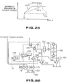
- Fig. 25 is a hydraulic circuit diagram which illustrates a conventional control system for the lock-up clutch.
- This control system includes a lock-up clutch 4, a torque converter 2, a transmission tank 100, a strainer 101, a hydraulic pump 5, a main relief valve 102, a torque converter relief valve 103, a rear brake ring 104, an oil cooler 105, a plurality of oil filters 106, a cooling relief valve 107, a lubricating relief valve 108, a transmission lubricating section 109, a lock-up modulation valve 110 and a solenoid valve 120.
- the lock-up clutch 4 is controlled with respect to its operative engagement, disengagement from the operatively engaged state and gradual increasing of hydraulic pressure by operating the lock-up modulation valve 110 via the solenoid valve 120.
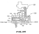
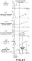
- Fig. 26 is a schematic sectional view which illustrates by way of example the inner structure of such a conventional modulation valve 110 and solenoid valve 120 and Fig. 27 shows a plurality of characteristic diagrams for respective component each illustrating how characteristics vary during speed changing (i.e., shift change) as time elapses.
- a lock-up "OFF" signal is first sent to a solenoid of the solenoid valve 120 (time t 1 ).
- the solenoid valve 120 is brought in an opened state as shown in Fig. 25, whereby pilot hydraulic pressure set by the main relief valve 102 flows through the solenoid valve 120 to displace a piston 130 of the modulation valve 110 in the leftward direction.
- a port D which has been communicated with the lock-up clutch 4 is closed with the spool 132 and thereby hydraulic oil in the lock-up clutch 4 is drained.
- a lock-up "ON" signal is sent to the solenoid of the solenoid valve 120 (time t 2 ).
- the solenoid valve 120 is shifted to a closed state so that working oil which has thrusted the piston 130 is drained via the solenoid valve 120.
- pressure of the working oil which has thrusted the piston 130 is reduced to a level of 0 Kg/cm 2 , causing the spool 132 to be displaced in the rightward direction by a spring 133 until the valve 110 is brought in an opened state. Consequently, main hydraulic oil flows in an order of A ⁇ C ⁇ D and is introduced into the lock-up clutch 4.
- the lock-up clutch 4 is fully filled with hydraulic oil.
- hydraulic oil which flows through a drilled hole in the valve body 136 to reach a hydraulic chamber behind a piston 139 via an orifice 138 in the cover 137 thrusts the piston 139 in the rightward direction.
- hydraulic pressure in the lock-up clutch 4 is increased.
- the lock-up clutch 4 when the lock-up clutch 4 is to be brought in an operatively engaged state, it is not filled with hydraulic oil and thereby it fails to be brought in an operatively engaged state, unless hydraulic oil having hydraulic pressure higher than the hydraulic pressure P t in the torque converter 2 is supplied to the lock-up clutch 4.
- the differential pressure P s caused when the clutch hydraulic pressure P is raised up to the initial hydraulic pressure P a will be hereinafter referred to as an actual initial hydraulic pressure.
- a conventional apparatus for controlling a lock-up clutch is constructed such that the initial hydraulic pressure P a is set appreciably higher than the hydraulic pressure P t in the torque converter 2 and hydraulic pressure for the lock-up clutch 4 is then gradually increased from the initial hydraulic pressure P a .
- the hydraulic pressure P t in the torque converter 2 varies as an engine speed varies.
- the actual initial hydraulic pressure P s varies as the hydraulic pressure P t in the torque converter 2 varies.
- the conventional control system since the initial hydraulic pressure P a in the lock-up clutch 4 is kept unchanged, e.g., when the hydraulic pressure P t in the torque converter 2 is increased, the actual initial hydraulic pressure P s is reduced.
- the initial hydraulic pressure P a to be given by the modulation valve 110 is set to such a high pressure that the actual initial hydraulic pressure P s is not less than zero or is not equal to zero.
- a period of clutch engaged time i.e., filling time
- a malfunction such as a large magnitude of shock caused by speed changing (shift change) occurs (see Fig. 27(f)).
- Figs. 28(a), (b) and (c) show how hydraulic pressure in a first speed clutch, hydraulic pressure in a second speed clutch and hydraulic pressure in a lock-up clutch vary as time elapses, while taking account of speed changing, e.g., from the first speed to the second speed, respectively.
- the filling time t f represents a time for which hydraulic oil is filled in an empty clutch pack at the rear stage clutch. When the clutch pack is fully filled with hydraulic oil, the filling time is terminated and hydraulic pressure in the clutch at the rear stage (clutch for second speed) starts increasing.
- the period of time t 1 to t 2 for which output torque is reduced to zero is existent due to the above-described two factors and the foregoing period of time offers a factor of breathing at the time of speed changing or degrading a property of acceleration.
- the conventional modulation valve 110 provides an uniformly extending firm pattern of hydraulic oil in the lock-up clutch and thereby a characteristic of gradual increasing of hydraulic pressure at the time of starting of forward movement of the vehicle or during speed changing is kept constant at all times.
- the lock-up clutch When the lock-up clutch is brought in an operatively engaged state, the input shaft of the transmission is connected directly to the output shaft of the engine. This permits variation of torque of the engine to be transmitted to the output shaft of the transmission.
- the conventional apparatus since the lock-up clutch is supplied with hydraulic oil having a comparatively high pressure during normal running of the vehicle, variation of torque of the engine is transmitted to the output shaft of the transmission as it is left unchanged. Due to this problem, the conventional apparatus does not carry out lock-up running not only in a low speed region where the engine is rotated at a low speed but also in a high speed region where the engine is rotated at a comparatively high speed. This leads to another problem that the engine is rotated with a degraded property of fuel consumption.
- An object of the present invention is to provide an apparatus and a method for controlling a lock-up clutch wherein variation of the actual initial hydraulic pressure corresponding to variation of hydraulic pressure in the torque converter can be prevented reliably.
- object of the present invention is to provide an apparatus and a method for controlling a lock-up clutch wherein a phenomenon of breathing during speed changing can be prevented by eliminating a period of time for which output torque during speed changing is reduced to a level of zero, a property of acceleration can be improved and shock caused by speed changing and locking-up can be reduced substantially.
- Another object of the present invention is to provide an apparatus and a method for controlling a lock-up clutch wherein a property of fuel consumption can be improved by frequently executing lock-up running of the vehicle.
- an apparatus for controlling a lock-up clutch wherein the apparatus includes a pressure control valve which is constructed such that hydraulic pressure at an output port leading to the lock-up clutch is exerted on one pressure receiving surface of a spool and the other pressure receiving surface is thrusted by an actuator adapted to generate a thrust force in response to an electrical command, and controlling means for allowing the electrical command to be inputted into the pressure control valve for carrying out control for opening/closing of the pressure control valve and gradual increasing of hydraulic pressure in response to the electrical command, whereby hydraulic pressure in a torque converter can be exerted on the pressure receiving surface on the actuator side of the pressure control valve.
- hydraulic pressure in the torque converter is fed back to the pressure control valve so that hydraulic pressure in the lock-up clutch is added with a bias corresponding to the hydraulic pressure in the torque converter.
- This causes a sum of hydraulic pressure generated in correspondence to the electrical command and hydraulic pressure in the torque converter to be exerted on the lock-up clutch. Consequently, the hydraulic pressure in the torque converter to be exerted on the back pressure portion of a piston of the lock-up clutch is canceled with the hydraulic pressure in the torque converter which has fed back to the pressure control valve.
- operative engagement of the lock-up clutch can be controlled by an electronic type pressure control valve which can output an arbitrary intensity of hydraulic pressure in response to the electrical command, whereby hydraulic pressure in the lock-up clutch can gradually be increased in an arbitrary manner.
- hydraulic pressure in the torque converter is fed back to the pressure control valve, variation of the hydraulic pressure in the torque converter has no effect on the hydraulic pressure generated in response to the electrical command, i.e., the hydraulic pressure practically relating to the operative engagement of the lock-up clutch, and the actual initial hydraulic pressure can always be maintained at a constant low pressure by holding a value of the electrical command at a constant low value at the time of completion of the filling.
- fluctuation of the filling time can be suppressed and shock caused by speed changing can be reduced.
- the apparatus includes a first valve including a spool which is formed with an orifice at an output port leading to the lock-up clutch, the first valve being opened and closed by differential pressure across the orifice and resilient force of a spring and having an inlet port through which hydraulic oil delivered from a hydraulic pump is supplied, a second valve including a spool of which one pressure receiving surface receives hydraulic pressure before the orifice of the first valve and of which other pressure receiving surface is thrusted by an actuator adapted to generate thrust force in response to an electrical command, the second valve having an inlet port through which hydraulic oil delivered from the hydraulic pump is supplied and an outlet port leading to a region located before the orifice of the first valve, filling completion detecting means for detecting completion of filling of the lock-up clutch with hydraulic oil based on movement of the spool of the first valve, and controlling means for allowing an electrical command to be inputted into the second valve to carry out control for opening/closing of the second valve and gradual increasing of hydraulic pressure, whereby hydraulic
- initial hydraulic pressure in the lock-up clutch can be reduced to a level near to the hydraulic pressure in the torque converter with the result that advantageous effects such as reduction of shock caused by speed changing or the like can be obtained.
- the apparatus includes a first valve for supplying hydraulic oil to a lock-up clutch from a hydraulic pump, the first valve including a spool of which one pressure receiving surface receives hydraulic pressure at an output port leading to the lock-up clutch and of which other pressure receiving surface comes in contact with one end of a spring of which other end in turn comes in contact with a piston, hydraulic pressure in a predetermined chamber into which hydraulic oil is introduced from the output port being exerted on the piston, a second valve for controlling opening/closing of the first valve in response to an electrical command inputted in an ON/OFF fashion, a third valve adapted to be shifted in response to an electrical command inputted in an ON/OFF fashion based on determination as to whether hydraulic oil in the hydraulic chamber of the first valve should be drained or not, and controlling means for controlling a shifting operation of each of the second and third valves such that the second valve is maintained in an ON state for a predetermined period of time in response to an electrical command inputted into the second valve during speed changing and the third
- the first valve is opened by a controlling operation performed by the controlling means during speed changing so that hydraulic oil delivered from the hydraulic pump is supplied to the lock-up clutch and hydraulic oil in the hydraulic chamber of the first valve is drained.
- hydraulic pressure in the lock-up clutch is reduced to a predetermined hydraulic pressure which has been predetermined by initial resilient force of the spring and other pressure receiving surface of the spool and thereafter it is gradually increased from the time point when the electrical command inputted into the third valve is turned off.
- hydraulic pressure in the lock-up clutch can be reduced to a predetermined pressure of which value is not zero, without drainage of hydraulic oil from the lock-up clutch.
- the apparatus since the apparatus is provided with a modulation valve for discharging hydraulic oil in a predetermined hydraulic chamber thereof to a drain port, hydraulic pressure in the lock-up clutch is reduced to a predetermined pressure during speed changing and the reduced hydraulic pressure is gradually increased after it is maintained for a certain period of time, no filling time is required for allowing the lock-up clutch to be fully filled with hydraulic oil. Consequently, shock caused at the time of completion of the filling can be reduced and a property of acceleration during speed changing can be improved.
- the lock-up clutch and a plurality of speed changing clutches have a plurality of solenoid valves separately connected thereto.
- the solenoid valve operatively associated with the lock-up clutch is turned off at the time point of the foregoing confirmation and the solenoid valve corresponding to the speed changing clutch to be next brought in an operatively engaged state is controlled so as to start gradual increasing of hydraulic pressure in the speed changing clutch.
- the solenoid valve for the speed changing clutch which has been currently brought in an operatively engaged state is turned off at the time point of termination of the filling time.
- the lock-up clutch and the clutch at the front stage are held in an operatively engaged state till the time point of termination of the filling time of the clutch to be next brought in an operatively engaged state, there is no fear that output torque is reduced to a level of zero for a period of filling time.
- an occurrence of breathing during speed changing can be prevented and a property of acceleration can be improved.
- a pressure control valve corresponding to a speed changing clutch to be next brought in an operatively engaged state is actuated as speed changing is started.
- hydraulic pressure in the foregoing speed changing clutch (representative of the speed changing clutch to be next brought in an operatively engaged state) is calculated at the time point of starting of the speed changing and then hydraulic pressure to be added to the speed changing clutch which has been currently held in an operatively engaged state is calculated for a period of time from starting of the speed changing till completion of the filling, whereby torque before the speed changing can be coordinated with torque after the speed changing. Consequently, shock caused by the speed changing can be reduced and thereby smooth speed changing can be accomplished.
- the apparatus includes an electronic type pressure control valve connected to the lock-up clutch to generate hydraulic pressure in the lock-up clutch in response to an inputted electrical command, first detecting means for detecting an extent of opening of a throttle (throttle displacement), second detecting means for detecting weight of a vehicle, third detecting means for detecting a gear ratio of the transmission, the gear ratio being determined depending on the current speed stage, and controlling means for calculating a gradient of gradually increasing of hydraulic pressure (acceleration of increasing of hydraulic pressure) based on detection outputs from the first, second and third detecting means so as to allow an electrical command corresponding to the calculated gradient to be inputted into the pressure control valve.
- first detecting means for detecting an extent of opening of a throttle (throttle displacement)
- second detecting means for detecting weight of a vehicle
- third detecting means for detecting a gear ratio of the transmission, the gear ratio being determined depending on the current speed stage
- controlling means for calculating a gradient of gradually increasing of hydraulic pressure (acceleration of increasing of hydraulic pressure) based on detection output
- a jerk value J serving as a value for evaluating lock-up shock (representative of a rate of variation of acceleration as time elapses).
- dP/dt 1 K ⁇ ⁇ ⁇ I ⁇ J G
- K and ⁇ are a known value, respectively, a characteristic of gradual increasing of hydraulic pressure in the lock-up clutch, i.e., dP/dt can be obtained by I, J and G.
- a target jerk value is determined by a quantity of throttle
- an optimum dP/dt can be obtained by detecting the quantity of throttle (J), the vehicle weight (I) and the speed reduction ratio (G). Then, an electrical command is inputted into the pressure control valve corresponding to the thus obtained dP/dt, after the hydraulic pressure is gradually increased.
- the apparatus is provided with a pressure control valve in operative association with the lock-up clutch so that the pressure control valve is actuated in response to an electrical signal.
- hydraulic pressure in the lock-up clutch is controlled such that it assumes a value of hydraulic pressure corresponding to the calculated value of output torque of the engine or a value of hydraulic pressure corresponding to a value appreciably higher than the calculated value.
- hydraulic pressure in the lock-up clutch is gradually increased from such an operatively engaged state that hydraulic pressure in the lock-up clutch is held at a predetermined low pressure without complete releasing of the lock-up clutch from the operatively engaged state. Consequently, shock caused by locking-up during speed changing can be reduced.
- a timing of starting of the gradual increasing of hydraulic pressure is detected so as to allow the gradual increasing of hydraulic pressure to be started in response to the foregoing detection.
- hydraulic pressure in the lock-up clutch is reduced to a value approximately corresponding to output torque from the engine during running of the vehicle, transmission of variation of the engine torque can be suppressed, whereby running of the vehicle in the lock-up state can be carried out from a low rotational region with the result that a characteristic of fuel consumption can be improved remarkably.
- Fig. 1 is a block diagram which schematically illustrate by way of example the structure a speed changing system to which the present invention is applied
- Fig. 2 is a hydraulic circuit diagram which illustrates by way of example the inner structure of an unit for supplying a clutch with hydraulic oil in the speed changing system in Fig. 1
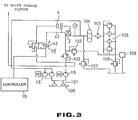
- Fig. 3 is a hydraulic circuit diagram which schematically illustrates an apparatus for controlling a lock-up clutch in accordance with an embodiment of the present invention
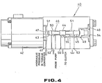
- Fig. 4 is a sectional view which illustrates by way of example the inner structure of an electronic type pressure control valve for the apparatus in accordance with the embodiment of the present invention
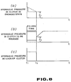
- Fig. 5 is a time chart illustrating a characteristic of hydraulic pressure for the clutch for the apparatus in accordance with the embodiment of the present invention
- Fig. 1 is a block diagram which schematically illustrate by way of example the structure a speed changing system to which the present invention is applied
- Fig. 2 is a hydraulic circuit diagram which illustrates by way of example the inner structure of an unit for supplying a clutch with
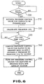
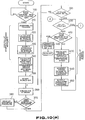
- FIG. 6 is a flowchart which schematically illustrates an apparatus for controlling a lock-up clutch in accordance with other embodiment of the present invention
- Fig. 7 shows a plurality of graphs which illustrate by way of example variation of hydraulic pressure in a clutch for speed changing and the lock-up clutch with reference to the flowchart in Fig. 6,
- Fig. 8 shows a plurality of graphs which illustrate by way of example variation of hydraulic pressure in a clutch for speed changing and a lock-up clutch in accordance with another embodiment of the present invention
- Fig. 9 is a flowchart which illustrates operations of the apparatus shown by the graphs in Fig. 8
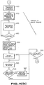
- Fig. 10 is a flowchart which illustrates operations of the apparatus in accordance with further another embodiment of the present invention
- FIG. 11 shows a plurality of time charts illustrating behaviors of each section in the apparatus at the time of starting of forward movement of a vehicle
- Fig. 12 shows a plurality of graphs illustrating a relationship among the number of revolutions of an engine, a quantity of throttle and output torque from the engine
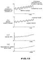
- Fig. 13 shows a plurality of time charts illustrating behaviors of each section in the apparatus during running of the vehicle
- Fig. 14 is a time chart illustrating a command indicative of hydraulic pressure in the lock-up clutch
- Fig. 15 is an explanatory view schematically illustrating one method of determining a timing for starting build-up
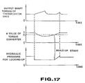
- Figs. 16 and 17 show a plurality of time charts, respectively, which schematically illustrate other method of determining a timing of starting build-up
- Fig. 15 is an explanatory view schematically illustrating one method of determining a timing for starting build-up
- Figs. 16 and 17 show a plurality of time charts, respectively, which schematically illustrate other method of determining a timing of
- FIG. 18 is a hydraulic circuit diagram which illustrates an apparatus for controlling a lock-up clutch in accordance with further another embodiment of the present invention
- Fig. 19 is a sectional view which illustrates by way of example the inner structure of an electronic type pressure control valve for the apparatus in Fig. 18,
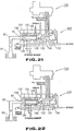
- Fig. 20 is a hydraulic circuit diagram which schematically illustrates an apparatus for controlling a lock-up clutch in accordance with further another embodiment of the present invention
- Figs. 21 and 22 are a schematic sectional view of a pressure control valve, respectively, which illustrates by way of example the inner structure of the pressure control valve for the apparatus
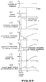
- Fig. 23 shows a plurality of time charts which illustrate by way of example operations of the apparatus during speed changing
- Fig. 24 is a time chart which illustrates variable control for a rate of gradual increasing of hydraulic pressure in accordance with a duty control process
- Fig. 25 is a hydraulic circuit diagram which illustrates by way of example a conventional apparatus for controlling a lock-up clutch
- Fig. 26 is a schematic sectional view which illustrates by way of example the inner structure of a pressure control valve for the conventional apparatus
- Figs. 27 and 28 show a plurality of time charts, respectively, which illustrates by way of example operations of the conventional apparatus
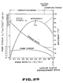
- Fig. 29 is a graph which illustrates a characteristic curve of a torque converter for the conventional apparatus.
- Fig. 1 is a block diagram which schematically illustrates the whole structure of a speed changing system to which the present invention is applied. Output from an engine 1 is transmitted to a transmission 3 via a torque converter 2 and then output from the transmission 3 is transmitted further to driving wheels 12 via a final speed reduction unit 11. As is apparent from the drawing, a lock-up clutch 4 is interposed between input and output shafts of the torque converter 2 for the purpose of making direct operative connection therebeteen.
- the engine 1 is equipped with an engine rotation sensor 6 which outputs a signal corresponding to the number n 1 of revolutions of the engine 1, while the transmission 3 is equipped with rotation sensors 7 and 8 wherein the rotation sensor 7 outputs a signal corresponding to the number n 2 of revolutions of an input shaft 2a of the transmission 3 and the rotation sensor 8 outputs a signal corresponding to the number n 3 of revolutions of an output shaft 3a of the transmission 3.
- the rotation sensor 7 outputs a signal corresponding to the number n 2 of revolutions of an input shaft 2a of the transmission 3
- the rotation sensor 8 outputs a signal corresponding to the number n 3 of revolutions of an output shaft 3a of the transmission 3.
- a throttle quantity sensor 13 detects a quantity of depressing of a throttle pedal and then inputs into the controller 10 a signal S indicative of the quantity of depressing of the throttle pedal.
- a vehicle weight sensor 14 detects a vehicle weight I (representing a sum of weight of a vehicle body and weight of load placed on the vehicle body) and then inputs a detected value into the controller 10.
- a shift selector 15 inputs into the controller 10 a signal indicative of one of shift positions (R, N, D , 1 ---) selected by a shift lever 16.
- the transmission 3 includes four speed changing clutches 21, 22, 23 and 24, and a required clutch corresponding to a speed stage which has been determined by one of the clutches 21, 22, 23 and 24 is selectively actuated by hydraulic pressure supplied from a clutch hydraulic pressure supplying unit 9 to make operative engagement for the foregoing clutch.
- the clutch hydraulic pressure supplying unit 9 is constituted mainly by separately operable electronic control type pressure control valves 31, 32, 33 and 34 for supplying hydraulic pressure to the four speed changing clutches 21 to 24 to separately actuating them and a relief valve 35.
- the lock-up clutch 4 has a lock-up clutch hydraulic pressure supplying unit 5 connected thereto to supply hydraulic pressure to the lock-up clutch 4.
- the item (1) is concerned with structure which is made in consideration of the fact that the hydraulic pressure P t in the torque converter 2 is exerted on the back pressure portion of a piston of the lock-up clutch 4, and this structure will be described in more details below with reference to Figs. 3 to 5.
- Fig. 3 is a hydraulic circuit diagram which schematically illustrates by way of example an inner structure of the lock-up clutch hydraulic pressure supplying unit 5.
- the lock-up clutch hydraulic pressure supplying unit 5 is such that an electronic type pressure control valve 40 is substituted for the lock-up modulation valve 110 and the solenoid valve 120 both of which are shown in Fig. 25.
- Other components rather than the electronic type control valve 40 are same as those in Fig. 25 and represented by same reference numerals. Thus, repeated description will be neglected for the purpose of simplification.
- the electronic type control valve 40 serves as a proportional control valve like the pressure control valves 31 to 34 which are actuated in response to an electronic command outputted from the controller 10.
- the electronic type control valve 40 is constructed such that hydraulic pressure in the torque converter 2 is fed back to the proportional solenoid 42 side of the pressure control valve 40 via a hydraulic passage 41 so as to prevent an actual initial hydraulic pressure P s from varying due to variation of the hydraulic pressure in the torque converter 2.
- Fig. 4 is a partially sectioned view which illustrates by way of example the structure of the control valve 40.
- the pressure control valves 31 to 34 connected to the speed changing clutches 21 to 24 are constructed in the same structure as the control valve 40.
- the pressure control valve 40 includes a spool 46 which comprises a first piston portion 43, a second piston portion 44 and a third piston portion 45.
- the left-hand end of the spool 46 comes in contact with a plunger 47, while the right-hand end of the spool 46 comes in contact with a retainer 49 which is resiliently energized in the leftward direction by a spring 48.
- the first piston portion 43 and the second piston portion 44 define a hydraulic chamber 50 and the second piston portion 44 and the third piston portion 45 define a hydraulic chamber 51.
- the hydraulic chamber 50 is communicated with an input port 52 and the hydraulic chamber 51 is communicated with a tank port 53.
- a hydraulic chamber 54 in which the spring 48 and the retainer 49 are accommodated is communicated with an output port 56 via a hydraulic passage 55.
- the hydraulic pressure P t in the torque converter 2 is introduced into a hydraulic chamber 57 located on the proportional solenoid 42 side.
- the proportional solenoid 42 is provided to serve as an actuator for displacing the spool 46, and a plunger 47 of the proportional solenoid 46 comes in contact with the left-hand end surface of the spool 46.
- the proportional solenoid 42 has such a characteristic that a thrust force F of the plunger 47 is in proportion to an input current i.
- the spool 46 is actuated such that the thrust force F of the plunger 47 is balanced with the foregoing force represented by A a ⁇ P d , i.e., a well-balanced relationship as represented by the following equation is satisfactorily established therebetween.
- F Aa ⁇ Pd
- the spring 48 serves to displace the spool 46 in the leftward direction and, since a spring having a small spring constant is used for the spring 48, the foregoing description has been made while not taking account of a function of the spring 48.
- hydraulic pressure in the lock-up clutch 4 is reduced to a level of substantially zero for a period of filling time t f until the clutch pack is filled with hydraulic oil, and thereafter it is raised up to the initial pressure P c on completion of the filling.
- the spring 48 serves to displace the spool 46 in the leftward direction, and since a spring having a small spring constant is used for the spring 48, the above Equation (5) has been formulated while not taking account of the function of the spring 48.
- Equation (1) can be transformed in the following manner.
- Pc F A b + Pt
- the lock-up actual initial hydraulic pressure P s derived by subtracting from the clutch initial pressure P c the hydraulic pressure P t in the torque converter 2 exerted on the back pressure portion of the piston of the lock-up clutch 4 can be expressed by the following equation. Consequently, the hydraulic pressure P t in the torque converter 2 is canceled with the foregoing lock-up actual initial hydraulic pressure P s .
- the pressure control valve 40 can suppress variation of the lock-up actual initial hydraulic pressure P s due to variation of the hydraulic pressure P t in the torque converter 2. Therefore, there is no need of presetting the initial hydraulic pressure P c to a higher level while taking account of variation of the hydraulic pressure P t in the torque converter as is the case with the conventional control system.
- the lock-up actual initial hydraulic pressure P s can assume a constant value at all times and the initial pressure P c can be maintained at a lower pressure, if the solenoid driving current i at the time point of completion of the filling is determined to hold a constant low pressure.
- This item (2) is concerned with timing control to be carried out when the lock-up clutch 4 is turned off during speed changing.
- operations of the controller 10 will be described with reference to a flowchart in Fig. 6 and and a plurality of time charts in Fig. 7.
- the controller 10 determines whether or not speed changing should be performed based on outputs from the rotation sensor 6 and the throttle quantity sensor 13 during running of the vehicle (step 200).
- the controller 10 first actuates the pressure control valve 32 for the second speed clutch 22 (step 210).
- the controller 10 calculates a clutch hydraulic pressure P 2 to be exerted on the speed changing clutch 22 after the filling time t f elapses (step 220).
- So-called speed changing shock takes place due to difference between output torque from the transmission 3 just prior to speed changing and output torque from the transmission 3 immediately after the speed changing. For the reason, an occurrence of the speed changing shock can be prevented by performing speed changing so as to eliminate the foregoing difference appearing between the foregoing two torques.
- a primary coefficient (STP) and a torque ratio (ST) representative of performances of the torque converter 2 can be calculated by deriving a ratio of the number of revolutions of the input shaft 1a to the number of revolutions of the output shaft 2a of the torque converter 2, i.e., an e value which is equal to n 2 /n 1 .
- Tp STP ⁇ (n1/1000) 2
- Tt Tp ⁇ ST
- a value of the torque converter output torque T t can be calculated in accordance with the above equations based on the primary coefficient (STP) and the torque ratio (ST).
- the torque T B on the output shaft of the transmission 3 at the time point t 1 can be derived in accordance with the following equation.
- TB G ⁇ Tt where G designates a gear ratio of the whole transmission 3.
- a frictional torque of the clutch at the time point t 2 of completion of the filling i.e., a friction torque T c on the second speed clutch 22 to be next brought in an engaged state
- Tc Kc ⁇ ⁇ ⁇ P
- K c designates a clutch friction coefficient at the time of completion of the filling
- V of clutch discs designates a clutch friction coefficient at the time of completion of the filling which is a function of the relative rotational speed V of clutch discs
- P designates a hydraulic pressure in the clutch.
- the friction torque T c can be converted into a torque TA on the output shaft of the transmission 3 at the time point t 2 of completion of the filling by calculation to be carried out in accordance with the following Equation (16).
- g' designates a gear ratio between the clutch to be brought in an operatively engaged state at the time of completion of the filling (second speed clutch) and the output shaft of the transmission.
- the clutch friction coefficient in the above Equation (17) is a function of the number of revolutions of the clutch disc and therefore it is impossible to previously know it.
- the number of relative revolutions of the friction discs at the time of completion of the filling can be derived from the number n 2 of revolutions of the output shaft of the torque converter detected by the rotation sensor 7, a gear ratio of the transmission 3 between before and after the speed changing and the number n 3 of revolutions of the output shaft of the transmission detected by the rotation sensor 8. This makes it possible to derive the clutch friction coefficient at the time of starting of the speed changing.
- the controller 10 calculates hydraulic pressure P 2 to be used for the speed changing clutch 32 based on the Equation (17).
- the controller 10 determines whether the filling time is terminated or not (step 230). In this case, the determination on termination of the filling time is made using a timer (not shown). Alternatively, in view of the phenomenon that flowing of hydraulic oil, e,g., in the speed changing clutch 22 is substantially interrupted, termination of the filling time may be detected by a sensor which is disposed midway of a hydraulic pressure supplying passage to sense the foregoing phenomenon.
- the controller 10 transmits a control signal to the pressure control valve 32 so as to allow the clutch hydraulic pressure P 2 derived at the step 220 to be exerted on the speed changing clutch 22 (step 240). Further, the controller 10 turns off the pressure control valve 31 operatively associated with the speed changing clutch 21 for the first speed which has been currently brought in an operatively engaged state, at the time point t 2 of termination of the filling time. In addition, the controller 10 outputs a lock-up stop command to the pressure control valve 40 connected to the lock-up clutch 4 at the time poit 2 of termination of the filling time to turn off the lock-up clutch 4 (step 250).
- hydraulic pressure in the speed changing clutch 22 is gradually increased until it is maintained at a preset pressure.
- the controller 10 turns off the lock-up clutch 4 at the time point t 2 of termination of the filling time in the above-described manner. This makes it possible to avoid a malfunction that output torque from the transmission 3 is reduced to zero due to arrangement of the torque converter 2 for the period of filling time as is the case with the conventional control system which turns off the lock-up clutch at the time point t 1 of outputting of a speed changing command.
- the clutch hydraulic pressure P 2 derived at the step 220 is exerted on the speed changing clutch 22 for second speed at the time point t 2 of completion of the filling.
- torque on the output shaft of the transmission 3 just before speed changing becomes equal to torque on the output shaft of the transmission at the time of completion of the filling, whereby an occurrence of the speed changing shock can be prevented effectively.
- hydraulic pressure in the speed changing clutch 21 for first speed is transiently decreased after the pressure control valve 22 is turned off. Accordingly, there arises an operative state that the second speed clutch 22 starts its operative engagement before the first speed clutch 21 becomes inoperative, and this may cause variation of torque to some extent. To prevent such phenomenon from taking place, as shown in Fig.
- hydraulic pressure exerted on the first speed clutch 21 is previously decreased to a properly determined level of P 1 for the period of time from the time point t 1 when a speed changing command is issued till the time point t 2 when the second speed clutch 22 starts operative engagement and then hydraulic pressure in the first speed clutch 21 is reduced to zero at the time point t 2 .
- the hydraulic pressure P 1 may assume any value which assures that a value of output torque for the period of filling time between the time point t 1 and the time point t 2 shown in Fig. 7(b) can be maintained.
- a value indicative of the hydraulic pressure P 1 can be derived in accordance with the Equations (14) and (16).
- Fig. 9 illustrates a procedure of processings to be performed in the above-described manner.
- a step 225 is executed between the step 220 and the step 230 shown in Fig. 6.
- the controller 10 calculates a hydraulic pressure P 1 to be exerted on the speed changing clutch 21 which has been currently brought in an operatively engaged state, for the period of time between the time point t 1 and the time point t 2 and controls the pressure control valve 31 so as to allow hydraulic pressure in the clutch 21 to reach the calculated hydraulic pressure P 1 .
- the following two methods of varying hydraulic pressure in the speed changing clutch 21 by actuating the pressure control valve 31 are available.
- One of them is such that clutch hydraulic pressure is varied to the hydraulic pressure P 1 immediately after issuance of a speed changing command, as represented by solid lines in Fig. 8(a).
- the other one is such that hydraulic pressure is gradually varied to the hydraulic pressure P 1 after issuance of the speed changing command, as represented by a dotted line in Fig. 8(a).
- the hydraulic pressure P 1 in the speed changing clutch 21 is not necessarily identical to the hydraulic pressure P 2 with which the speed changing clutch 22 starts its operative engagement.
- the lock-up clutch 4 is turned off at the time point t 2 when the filling time is terminated, as shown in Fig. 8(c).
- hydraulic pressure in the clutch which has been brought in an operatively engaged state is decreased to an adequate level for the period of time until the filling time is terminated and the hydraulic pressure in the clutch is then reduced to zero when the filling time is terminated, whereby variation of torque caused when a next clutch starts its operative engagement can be prevented with higher accuracy.
- output torque T t from the torque converter 2 may be derived based on output torque from the engine 1 utilizing the previously known performances of output from the engine 1 or it may be derived directly by using a torque sensor.
- the item (3) is concerned with a control for modulating hydraulic pressure when the number of revolutions of the engine exceeds the minimum number of revolutions of the engine required for lock-up engagement after the vehicle starts its forward movement in response to a command issued by actuation of the shift lever 16.
- This control will be described below with reference flowcharts in Figs. 10(a) and (b) and a plurality of time charts in Fig. 11 illustrating characteristics relative to a command indicative of hydraulic pressure for locking-up or the like issued as time elapses.
- the controller 10 After the vehicle starts its forward movement, the controller 10 measures the number n 1 of revolutions of the engine based on output from the engine rotation sensor 6. When the number n 1 of revolutions of the engine exceeds the minimum number n r of revolutions of the engine (see Fig. 11(b)) required for locking-up (step 300), a trigger command indicative of high pressure is inputted in the solenoid 42 of the pressure control valve 40 for the lock-up clutch 4 for a predetermined period of time, whereby high pressure hydraulic oil is supplied to the lock-up clutch 4 to promote a processing of filling (step 310).
- a command indicative of hydraulic pressure is lowered to a value corresponding to hydraulic pressure (P t + ) higher than the hydraulic pressure in the torque converter 2 and this value is then maintained for a predetermined period of time (steps 320 and 330).
- P t + hydraulic pressure
- the reason why the lock-up clutch 4 is supplied with hydraulic pressure higher than the hydraulic pressure in the torque converter 2 in that way consists in that the hydraulic pressure in the torque converter 2 is exerted on the back pressure portion of a piston of the lock-up clutch 4.
- the hydraulic pressure in the torque converter 2 is substantially in proportion to the number of revolutions of the engine, it can be calculated based on outputs from the engine rotation sensor 6 and other sensors. Incidentally, in case where the number of revolutions of the engine varies few, a predetermined intensity of hydraulic pressure (corresponding to a value of the upper limit of variation) may be exerted on the lock-up clutch 4.
- the controller 10 confirms completion of the filling by carrying out control as time elapses or on the basis of outputs from a suitable filling detecting sensor and other sensors, the controller 10 gradually increases a command indicative of hydraulic pressure to be supplied to the pressure control valve 40 so as to allow the lock-up clutch 4 to be brought in an operatively engaged state, whereby hydraulic pressure in the lock-up clutch 4 can be increased gradually.
- a gradient of increasing of hydraulic pressure varies in dependence on an extent S of opening of the throttle and the weight I of the vehicle body.
- lock-up engagement at the time of starting of forward movement of the vehicle is accomplished at the minimum speed stage.
- a speed reduction ratio is added to the aforementioned parameters and then a build-up rate is properly varied in dependence on these parameter (vehicle weight, extent of opening of throttle and gear ratio) (step 340).
- the constant G relative to a speed reduction ratio is determined in dependence on the current speed stage but it includes a coefficient suggestive of the number of clutch plates superposed one above another and an area of respective clutch plate at individual speed stage. Therefore, this constant G has a value which differs to some extent depending on respective speed stage. Of course, in case where the number of clutch plates superposed one above another and an area of each clutch plate are same at respective speed stage, the constant G designates a speed reduction ratio itself.
- the second term P d ⁇ d t included in the bracket in the Equation (18) represents a term which is related to a case where there is a large magnitude of difference between static friction and dynamic friction. This term is largely affected at the time of completion of the operative engagement of the clutch but it may be neglected if it is found that there is no difference between the static friction and the dynamic friction.
- Equation (18) K G I ⁇ ⁇ d p d t
- I i.e., the weight of the vehicle can be obtained from an output from the vehicle weight sensor 14 and G, i.e., the constant relative to a speed reduction ratio can be obtained from the speed reduction ratio itself.
- J i.e., the jerk value represents a value indicative of shock to be used as a target. This value is determined by a magnitude of load (a smaller value is preferable for light load and a larger value is preferable for heavy load). Since load exerted on the vehicle body can not practically be measured but it is in proportion to power generated by the engine, the above target jerk value J can be determined based on the current extent of opening of the throttle. Namely, the jerk value J can be determined based on an output from the throttle quantity sensor 13. Incidentally, the jerk value J can be changed in proportion to the output from the throttle quantity sensor 13.
- the controller 10 measures the extent of opening of the throttle, the vehicle weight and the gear ratio and calculates the optimum build-up rate dp/dt so as to gradually increase hydraulic pressure based on the calculated dp/dt.
- dp/dt may previously be stored in a memory of the controller 10 using the extent of opening of the throttle, the vehicle weight and the gear ratio as variables, so as to allow dp/dt corresponding to detected values of these variables to be read from the memory, as required.
- data derived from actual measurements conducted with an actual vehicle may be used:
- the controller 10 measures an e value of the torque converter 2 (step 360) (the e value is represented n 2 /n 1 , wherein n 1 designates the number of revolutions of an input shaft of the torque converter 2 and n 2 designates the number of revolutions of an output shaft of the torque converter 2).
- the e value becomes "1" or a predetermined value "E o " very near to 1 (see Fig. 11(c))
- the gradual increasing of hydraulic pressure is terminated (step 390). If the hydraulic pressure in the lock-up clutch 4 exceeds the preset pressure P a indicative of the upper limit during the gradual increasing of hydraulic pressure before the e value reaches "1" or the preset value E o (see Fig.
- the controller 10 carries out control such that the hydraulic pressure in the lock-up clutch 4 is maintained at the upper limit indicative of the preset pressure P a for a certain period of time until the e value reaches E o (steps 370 and 380). It should be added that once the e value is obtained, the number of revolutions of the output shaft of the torque converter 2 may be derived using output from the transmission output shaft rotation sensor 8 and the gear ration.
- the item (4) is concerned with control to be carried out during normal running of the vehicle after speed changing or starting of forward movement of the vehicle.
- the controller 10 When control for gradually increasing hydraulic pressure is terminated, the controller 10 carries out control such that hydraulic pressure in the torque converter 2 is reduced to a value corresponding to output torque from the engine or a value P ⁇ appreciably larger than the first-mentioned value (see Fig. 11(a)).
- the controller 10 determines at a step 400 whether speed changing should be effected or not. Thereafter, when the controller 10 determined that speed changing should not be effected, it calculates torque T generated by the engine 1 based on the output S from the throttle quantity sensor 13 and the output n 1 from the engine rotation sensor 6, as long as the number n 1 of revolutions of the engine is decreased smaller than the minimum number n 2 of revolutions of the engine required for establishing a lock-up state (step 430).
- the torque T outputted from the engine is closely related to the number of revolutions of the engine 1 and the extent of opening of the throttle, and various values of torque T corresponding to respective values of these parameters are previously stored in the memory of the controller 10.
- the current engine torque T can be derived by reading from the memory the torque value corresponding to detection outputs from the engine rotation sensor 6 and the throttle quantity sensor 13.
- intermediate adequate values are derived using a processing of interpolation or the like.
- the controller 10 controls clutch hydraulic pressure such that the torque transmitted by the lock-up clutch 4 coincides with the engine output torque T derived from the number of revolutions of the engine and the extent of opening of the throttle or the torque transmitted from the lock-up clutch 4 assumes a value appreciably larger than the engine output torque T.
- T' K ⁇ ⁇ (v) ⁇ P
- the controller 10 derives the engine torque T from outputs from the throttle quantity sensor 13 and the engine rotation sensor 6, converts the derived torque value T or the value appreciably larger than the latter into a clutch pressure P in accordance with the Equation (21) (step 440) and then delivers a hydraulic pressure command corresponding to the converted clutch pressure P to the pressure control valve (step 450).
- the engine output torque T varies as shown in Fig. 13(b).
- the vehicle runs while the lock-up clutch pressure is reduced to the converted value derived by converting the engine output torque into hydraulic pressure (represented by a dotted line in Fig. 13(a)) or to hydraulic pressure appreciably larger than the converted value (represented by a solid line in Fig. 13(a))
- variation of output on the transmission output shaft due to variation of engine output torque can be reduced, whereby variation of output of the transmission output shaft can be suppressed as shown in Fig. 13(d), even when a large magnitude of variation is caused with the number of revolutions of the engine as shown in Fig. 13(c).
- the minimum number n r of revolutions of the engine relative to the lock-up engagement can be set to the lower speed side than the conventional apparatus, resulting in a property of fuel consumption being improved.
- the clutch hydraulic pressure is reduced to a level of the value P ⁇ corresponding to the engine output torque without delay when the e value of the torque converter reaches the present value E o .
- the clutch hydraulic pressure may be reduced to a level of the foregoing value P ⁇ after a predetermined period of time elapses, after hydraulic pressure is gradually increased and then the corresponding time measurement is carried out.
- Control relative to the item (5) is carried out during speed changing for the vehicle.
- the speed changing clutch is brought in operative engagement after the lock-up clutch is completely released from the operative state.
- the lock-up clutch is not, completely released from the operative state during the speed changing for the vehicle but half lock-up control is executed for gradually increasing hydraulic pressure after possibly low hydraulic pressure above the hydraulic pressure in the torque converter is maintained. Accordingly, during a controlling operation according to the present invention, there does not exist filling time required for fully filling the clutch pack with hydraulic oil.
- Fig. 14 is a diagram which illustrates variation of characteristics of a command indicative of lock-up hydraulic pressure during the speed changing of the vehicle as time elapses.
- the controller 10 calculates the pressure P t in the torque converter based on an output from the engine rotation sensor 6 (step 460 in Fig. 10(b)), reduces the hydraulic pressure in the lock-up clutch 4 to a level of (p t + ⁇ ) which represents a predetermined pressure ⁇ with the calculated value P t of pressure in the torque converter 2 added thereto and then holds this value of hydraulic pressure (P t + ⁇ ) for a short period of time (step 470).
- the controller 10 determines a build-up starting time point t s when gradual increasing of hydraulic pressure starts (step 480). To determine a timing of the build-up is started, the following three methods have been proposed.
- the method (a) is most simple and practical.
- a rotation sensor is required for each of them but the method (b) is a method advantageously employable for improving a characteristic of acceleration and the method (c) is a method advantageously employable for reducing of shock caused by speed changing.
- the controller 10 determines using any one of the aforementioned methods that the build-up starting time t s is reached (step 490), it measures the extent of opening of the throttle S, the vehicle weight I and the gear ratio, calculates an optimum build-up rate dp/dt based on the measured values in accordance with the above Equation (20) (step 500) and then gradually increases hydraulic pressure in response to the calculated value dp/dt in the same manner as the aforementioned controlling operation at the time of starting of forward movement of the vehicle (step 510).
- the operation of gradually increasing the hydraulic pressure is interrupted when the e value of the torque converter reaches "1" or the set value "E o " which is very near to 1 and, when the clutch pressure exceeds the upper limit set pressure P ⁇ before the e value reaches "1" or the set pressure value E o , the clutch pressure is maintained at a level of the upper limit set value P ⁇ in the same manner at the time of starting of forward movement of the vehicle (steps 520 to 550). Thereafter, as the vehicle runs, the controller 10 carries out control as described above in the item (4) so as to allow the lock-up pressure to assume a value corresponding to the engine output torque T.
- the item (6) i.e., the structure as shown in Fig. 18 is such that a flow rate detecting valve 60 is disposed in addition to the system structure as shown in Fig. 3.
- the flow rate detecting valve 60 is provided with a filling detecting sensor 61.
- same or similar other structural components as those in Fig. 3 are represented by same reference numerals. Thus, repeated description will not be required.
- the electronic type control valve 40 is a proportional control valve adapted to be actuated in response to an electrical command outputted from the controller 10 in the same manner as mentioned above.
- the hydraulic pressure in the torque converter is fed back to the proportional solenoid 42 side of the pressure control valve 20 via a hydraulic passage 41.
- the flow rate detecting valve 60 is disposed so as to allow hydraulic oil to be fed to the lock-up clutch 4 at a high flow rate during the filling operation to shorten a period of time required for the filling operation.
- the flow rate detecting valve 60 is provided with a filling detecting sensor 61 for detecting completion of the filling operation based on movement of the spool in the flow rate detecting valve 60.
- Fig. 19 is a schematic sectional view which illustrates by way of example the inner structure of the pressure control valve 40, the flow rate detecting valve 60 and the filling detecting sensor 61.
- hydraulic oil delivered from the hydraulic pump 15 is introduced into the flow rate detecting valve 60 via an input port 62 so that it is supplied to the lock-up clutch 4 via an output port 63. At this moment, a port 64 is kept closed.
- the electronic type pressure control valve 40 includes a spool 65 of which right-hand end comes in contact with a plunger 66 of the proportional solenoid 42 and of which left-hand end is resiliently supported by a spring 67. Hydraulic pressure in a hydraulic chamber 70 is introduced into a hydraulic chamber 69 which is defined by the spool 69 and the piston 68. Further, the pressure control valve 40 includes a hydraulic chamber 71 on the proportional solenoid 42 side into which the hydraulic pressure in the torque converter is introduced via a hydraulic passage 41.
- the flow rate detecting valve 60 includes a spool 72 which is formed with an orifice 73 on the output port 63 side.
- the left-hand end surface of the spool 72 is resiliently supported by a spring 74 and hydraulic pressure before the orifice 73 is delivered to a hydraulic chamber 75 via a hydraulic passage 76.
- An electromagnetic pick-up 61 serving as a filling detecting sensor is attached to the right-hand end surface of the flow rate detecting valve 60 with a housing cover 77 interposed therebetween.
- the controller 10 determines completion of the filling when the pick-up 61 detects movement of the spool 72 of the flow rate control valve 60. Namely, voltage induced by the pick-up 61 varies as the spool 72 is displaced toward or away from the pick-up 61, whereby movement of the spool 72 can be detected by detecting variation of the induced voltage.
- the controller 10 turns on the solenoid 42 of the pressure control valve 40.
- This permits the spool 61 of the pressure control valve 40 to be displaced in the leftward direction, whereby hydraulic oil delivered from the hydraulic pump 15 flows in the pressure control valve 40 via the input port 62 and the hydraulic passage 78.
- the hydraulic oil which has flowed in the pressure control valve 40 flows further in the flow rate detecting valve 60 via a hydraulic passage 70 and a port 79 so that it is delivered to the lock-up clutch 4 via the orifice 74 in the spool 72 and the output port 63.
- the hydraulic oil in the port 79 is introduced into the hydraulic chamber 75 via the hydraulic passage 76 in the spool 72.
- hydraulic pressure in the lock-up clutch 4 is kept at a level of almost zero for a period of filling time t f until the clutch pack is filled with hydraulic oil. On completion of the filling, it is raised up to the initial pressure P c .
- the detection signal of the pick-up 61 is inputted into the controller 10. After the controller 10 detects completion of the filling in response to the input signal, hydraulic pressure in the lock-up clutch 4 is gradually increased by gradually increasing a magnitude of electricity to be fed to the solenoid 42.
- the pressure P t in the torque converter 2 is fed back to the hydraulic chamber 71 on the solenoid 42 side of the pressure control valve 40 to cancel the pressure P t in the torque converter 2 which is exerted on the back pressure portion of the piston of the lock-up clutch 4, whereby variation of the lock-up actual initial hydraulic pressure P s due to variation of the hydraulic pressure in the torque converter 2 can be suppressed. Accordingly, the lock-up actual initial pressure P s can always assume a constant value by holding the solenoid driving current i constant at the time of completion of the filling.
- arrangement of the flow rate detecting valve 60 makes it possible to supply the lock-up clutch 4 with hydraulic oil at a high flow rate. Since the time of completion of the filling can exactly be determined by sensing movement of the spool 72 of the flow rate detecting valve 60 using the pick-up 61, hydraulic pressure in the lock-up clutch 4 at the time of completion of the filling, i.e., the initial pressure in the clutch can be reduced almost to a level of hydraulic pressure in the torque converter 2, whereby shock caused when the lock-up clutch 4 is brought in an operatively engaged state with the initial pressure can be reduced remarkably.
- completion of the filling is determined by detecting movement of the spool 72 of the flow rate detecting valve 60 using the pick-up 61.
- filling detecting means having any other structure may be employed, provided that it is proven that completion of the filling is detected based on movement of the spool 72 of the flow rate detecting valve 60.
- completion of the filling may be detected in such a manner that a piston disposed leftward of the spool 72 is resiliently supported by the spring 74 and displacement of the piston toward and away from the housing cover 77 is electrically detected as the spool 72 moves.
- the item (7) is concerned with a structure for a conventional hydraulic control system as shown in Fig. 25 having a solenoid valve 80 for the purpose of drainage added thereto, as shown in Fig. 20.
- a solenoid valve 80 for the purpose of drainage added thereto as shown in Fig. 20.
- Same or similar structural components as those in Fig. 25 are identified by same reference numerals. Thus, their repeated description will not be required.
- the solenoid valve 80 serves to bring hydraulic oil in the load piston control chamber of a modulation valve 110 to a drain port. With such a control system, hydraulic pressure in the lock-up clutch 4 is controlled by operation of the modulation valve 110, the solenoid valve 110 and the solenoid valve 80 (hereinafter referred to as a drain valve).
- Figs. 21 and 22 illustrate by way of example the inner structure of these three valves, respectively.
- a load piston control chamber 81 for allowing hydraulic pressure to be exerted on a piston 139 of the modulation valve 110 is communicated with a drain port via a hydraulic passage 82 and the drain valve 80 so that the drain valve 80 determines whether hydraulic oil should be drained or not.
- Fig. 23 shows a plurality of time charts as well as Fig. 1.
- Fig. 23(a) shows a command voltage to be given to the solenoid valve 120 by the controller 10
- Fig. 23(b) shows a command voltage to be given to the drain valve 80
- Fig. 23(c) shows hydraulic pressure P L in the piston chamber 81
- Fig. 23(d) shows hydraulic pressure P v at an outlet port of the modulation valve 110
- Fig. 23(e) shows hydraulic pressure in the lock-up clutch 4
- Fig. 23(f) shows a stroke of the piston 139
- Fig. 23(g) shows torque on the output shaft of the transmission.
- the controller 10 feeds the solenoid valve 120 with a command voltage so as to allow the solenoid valve 120 to be shifted to an "ON" state before speed changing, as shown in Fig. 23(a).
- the controller 10 feeds the drain valve 80 with a command voltage represented by "ON” (see Fig. 23(b)), whole the command voltage to the solenoid valve 120 is left unchanged at the "ON” state (see Fig. 23(a)).
- the controller 10 holds the drain valve 80 at the "ON" state for the period of lock-up delay time T 1 , and after the delay time T 1 elapses, the controller 10 reduces the command voltage to the drain valve 80 to a level of zero (time t 2 ). As a result, the drain valve 80 is shifted to the drain side so that hydraulic oil in the load piston control chamber 81 is quickly drained via the hydraulic passage 82. Thus, the load piston 139 is returned from the position shown in Fig. 22 to the position shown in Fig. 21, i.e., the position where a spring 133 is initially accommodated in the load piston 139 (Fig.
- the controller 10 reduces the command voltage to the drain valve 80 to zero to close the drain valve 80 (time t 2 ). Consequently, the hydraulic oil which has entered the load piston control chamber 81 via an orifice 138 is intercepted in the load piston control chamber 81, whereby the load piston 139 is displaced in the rightward direction. As the load piston moves in the rightward direction as shown in Fig. 22, the hydraulic pressure in the lock-up clutch 4 is increased gradually. Thereafter, when the load piston 139 collides with a stopper, gradual increasing of the hydraulic pressure is stopped to assume a certain value. Thereafter, this value of hydraulic pressure is maintained.
- the hydraulic pressure in the lock-up clutch is not completely released during the speed changing but the controller 10 carries out half lock-up control as shown Fig. 11 and Fig. 14 wherein hydraulic pressure in the hydraulic clutch is reduced to the initial pressure P o higher than the pressure P t in the torque converter.
- hydraulic pressure in the lock-up clutch can be built up from the value of initial hydraulic pressure corresponding to the hydraulic pressure at the time of completion of the filling in a good timing relationship.
- a characteristic of acceleration can be improved and shock appearing when the lock-up clutch is brought in an operatively engaged state can be reduced substantially, as shown in Fig. 23(g).
- the reason why the lock-up clutch is released during the speed changing consists in reduction of load to be carried by the speed changing clutch.
- thermal load to be carried by the clutch can be distributed to the speed changing clutch and the lock-up clutch by reducing torque to be transmitted via the lock-up clutch (i.e., by bringing the lock-up clutch 4 in a slippery state), resulting in durability of these clutches being improved.
- timing for starting the gradual increase of hydraulic pressure in the lock-up clutch (time t 2 ) can be determined in accordance with one of the following three methods.
- a build-up rate during gradual increasing of hydraulic pressure may be varied in dependence on the extent of opening of the throttle, the vehicle weight (weight of the vehicle body + quantity of load placed on the vehicle body) and the gear ratio of the transmission, as mentioned above.
- Variable control for determining such a build-up rate can easily be realized by carrying out duty control as shown in Fig. 24 in response to a voltage command to be given to the drain valve 80.
- duty ratios of 0 %, 50 % and 100 % are shown in Fig. 24.
- the present invention is advantageously employable for a speed changing unit including a lock-up clutch by way of which the input shaft of a torque converter is operatively connected to the output shaft of the torque converter which is installed on a construction machine such as a truck, a wheel loader or the like vehicle.
Abstract
Description
- This invention relates to a speed changing (shift change) system including a lock-up clutch by way of which input and output shafts of a torque converter are operatively connected to each other, wherein the technical improvement consists in that shock caused during speed changing or at the time of starting of forward movement of a vehicle is canceled, interruption of transmission of torque is prevented and cost for fuel consumption is reduced.
- A conventional speed changing (transmission) unit is constructed such that the output shaft of an engine is connected to the input shaft of a torque converter and the input shaft of a transmission is connected to the output shaft of the torque converter, while a lock-up clutch is interposed between the input and output shafts of the torque converter so as to operatively connect them to each other via the lock-up clutch.
- Such a lock-up clutch has the following five problems from the viewpoints of structure and control.
- Fig. 25 is a hydraulic circuit diagram which illustrates a conventional control system for the lock-up clutch. This control system includes a lock-
up clutch 4, atorque converter 2, atransmission tank 100, astrainer 101, ahydraulic pump 5, amain relief valve 102, a torqueconverter relief valve 103, arear brake ring 104, anoil cooler 105, a plurality ofoil filters 106, acooling relief valve 107, alubricating relief valve 108, atransmission lubricating section 109, a lock-up modulation valve 110 and asolenoid valve 120. The lock-up clutch 4 is controlled with respect to its operative engagement, disengagement from the operatively engaged state and gradual increasing of hydraulic pressure by operating the lock-upmodulation valve 110 via thesolenoid valve 120. - Fig. 26 is a schematic sectional view which illustrates by way of example the inner structure of such a
conventional modulation valve 110 andsolenoid valve 120 and Fig. 27 shows a plurality of characteristic diagrams for respective component each illustrating how characteristics vary during speed changing (i.e., shift change) as time elapses. - Specifically, with this control system, during speed changing, a lock-up "OFF" signal is first sent to a solenoid of the solenoid valve 120 (time t1). As a result, the
solenoid valve 120 is brought in an opened state as shown in Fig. 25, whereby pilot hydraulic pressure set by themain relief valve 102 flows through thesolenoid valve 120 to displace apiston 130 of themodulation valve 110 in the leftward direction. As thepiston 130 displaces aspool 132 in the leftward direction via thepiston 131, a port D which has been communicated with the lock-upclutch 4 is closed with thespool 132 and thereby hydraulic oil in the lock-upclutch 4 is drained. - Then, after a predetermined period of lock-up delay time for holding the lock-
up clutch 4 in an OFF state elapses, a lock-up "ON" signal is sent to the solenoid of the solenoid valve 120 (time t2). As a result, thesolenoid valve 120 is shifted to a closed state so that working oil which has thrusted thepiston 130 is drained via thesolenoid valve 120. Thus, pressure of the working oil which has thrusted thepiston 130 is reduced to a level of 0 Kg/cm2, causing thespool 132 to be displaced in the rightward direction by aspring 133 until thevalve 110 is brought in an opened state. Consequently, main hydraulic oil flows in an order of A → C → D and is introduced into the lock-up clutch 4. After a filling time tf elapses, the lock-upclutch 4 is fully filled with hydraulic oil. - At this moment, hydraulic oil which has been introduced through the port D enters a
hydraulic chamber 135 between thepiston 131 and thespool 132 via anorifice 134 with the result that hydraulic pressure Pv at an outlet of the valve is set to an initial pressure
piston 131 is balanced with resilient force (kx, where K designates a spring constant and x designate an initial displacement) (see Fig. 27(c)). Thereafter, hydraulic oil which flows through a drilled hole in thevalve body 136 to reach a hydraulic chamber behind apiston 139 via anorifice 138 in thecover 137 thrusts thepiston 139 in the rightward direction. As thepiston 139 moves in the rightward direction, hydraulic pressure in the lock-up clutch 4 is increased. - On the the hand, for the period tf of filling, hydraulic pressure in the lock-up
clutch 4 is held at a level of almost zero but it is gradually increased after it is raised up to initial hydraulic pressure Pa at the same time when the filling is completed (time t3). When thepiston 139 comes in contact with a stopper, increasing of hydraulic pressure is stopped and hydraulic pressure at this time becomes a set pressure Pb for the lock-up valve (time t4). - Operation of the
modulation valve 110 during the speed changing has been described above. The initial hydraulic pressure Pa and a characteristic of gradual increasing of hydraulic pressure derived from theconventional modulation valve 110 are firmly determined depending on the set load Kx of thespring 133, the pressure receiving area S1 of thepiston 131 and other factors. Thus, hydraulic pressure can not be changed arbitrarily. - Further, the foregoing control system is constructed such that the lock-
up clutch 4 is fully immersed in a hydraulic chamber of thetorque converter 2 and the hydraulic pressure Pt in thetorque converter 2 is exerted on the back pressure portion of a piston of the lock-up clutch 4 via a hydraulic passage 115 (see Fig. 25). Accordingly, with this control system, e.g., at the time point t3 when hydraulic pressure P in the lock-upclutch 4 is raised up to the initial hydraulic pressure Pa, the lock-up clutch 4 is practically operated with a differential pressure
torque converter 4 from the initial clutch pressure Pa, as shown in Fig. 27(d). Thus, when the lock-upclutch 4 is to be brought in an operatively engaged state, it is not filled with hydraulic oil and thereby it fails to be brought in an operatively engaged state, unless hydraulic oil having hydraulic pressure higher than the hydraulic pressure Pt in thetorque converter 2 is supplied to the lock-up clutch 4. Here, the differential pressure Ps caused when the clutch hydraulic pressure P is raised up to the initial hydraulic pressure Pa will be hereinafter referred to as an actual initial hydraulic pressure. - For the reason, a conventional apparatus for controlling a lock-up clutch is constructed such that the initial hydraulic pressure Pa is set appreciably higher than the hydraulic pressure Pt in the
torque converter 2 and hydraulic pressure for the lock-up clutch 4 is then gradually increased from the initial hydraulic pressure Pa. - However, the hydraulic pressure Pt in the
torque converter 2 varies as an engine speed varies. Thus, with the conventional control system, the actual initial hydraulic pressure Ps varies as the hydraulic pressure Pt in thetorque converter 2 varies. Accordingly, with the conventional control system, since the initial hydraulic pressure Pa in the lock-up clutch 4 is kept unchanged, e.g., when the hydraulic pressure Pt in thetorque converter 2 is increased, the actual initial hydraulic pressure Ps is reduced. - In this manner, with the conventional apparatus, since the actual initial hydraulic pressure Ps to be practically exerted on the lock-
up clutch 4 varies as hydraulic pressure in thetorque converter 2 varies, the initial hydraulic pressure Pa to be given by themodulation valve 110 is set to such a high pressure that the actual initial hydraulic pressure Ps is not less than zero or is not equal to zero. For the reason, with the conventional apparatus, a period of clutch engaged time (i.e., filling time) fluctuates with the result that a malfunction such as a large magnitude of shock caused by speed changing (shift change) occurs (see Fig. 27(f)). - Figs. 28(a), (b) and (c) show how hydraulic pressure in a first speed clutch, hydraulic pressure in a second speed clutch and hydraulic pressure in a lock-up clutch vary as time elapses, while taking account of speed changing, e.g., from the first speed to the second speed, respectively.
- According to the conventional control system, if a speed changing command is issued at the time t1, the first speed clutch and the lock-up clutch are turned off at this time t1 and hydraulic oil starts flowing in the clutch for second speed. As a result, at the time t1, hydraulic pressure exerted on the clutch for first speed and hydraulic pressure exerted on the lock-up clutch are reduced from a predetermined pressure to a level of zero, as shown Figs. 28(a) and (c). On the other hand, hydraulic pressure exerted on the clutch for second speed starts gradual increasing from the time t2, after the filling time tf elapses, as shown in Fig. 28(b).
- The filling time tf represents a time for which hydraulic oil is filled in an empty clutch pack at the rear stage clutch. When the clutch pack is fully filled with hydraulic oil, the filling time is terminated and hydraulic pressure in the clutch at the rear stage (clutch for second speed) starts increasing.
- As the filling time tf elapses, output torque from the speed changing unit is reduced to a level of zero, as shown in Fig. 28(d). The reason why such reduction occurs is attributable to the following two factors.
- The reason why the lock-up clutch is released during speed changing consists in reducing load to be carried by the speed changing clutch or suppressing consumption of energy generated by the engine. With the prior art, however, the lock-up clutch is turned off at the same time when the clutch at the front stage (clutch for first speed) is opened (time t1). While the lock-up clutch is turned off, engine output passes through the torque converter but, at the time of this operative state, a speed ratio of turbine to pump in the torque converter, i.e. an

- For the period of filling time tf until the clutch pack is fully filled with hydraulic oil, hydraulic pressure is not raised up to a level sufficient to bring the clutch in an operatively engaged state.
- In this manner, according to the conventional control system, the period of time t1 to t2 for which output torque is reduced to zero is existent due to the above-described two factors and the foregoing period of time offers a factor of breathing at the time of speed changing or degrading a property of acceleration.
- Usually, a system wherein at the time of speed changing, the lock-up clutch is completely released from the operatively engaged state (hydraulic oil in the clutch is drained, in other words, hydraulic pressure in the clutch is reduced to zero) and then pressurized hydraulic oil is supplied again (during speed changing, the vehicle runs with the use of the torque converter to reduce a load to be carried by the speed changing clutch) is employed for the conventional apparatus. This leads to such problems that time required for filling the lock-up clutch with hydraulic oil, i.e., the filling time fluctuates and a large magnitude of shock occurs when the lock-up clutch is brought in an operatively engaged state.
- As described above, the
conventional modulation valve 110 provides an uniformly extending firm pattern of hydraulic oil in the lock-up clutch and thereby a characteristic of gradual increasing of hydraulic pressure at the time of starting of forward movement of the vehicle or during speed changing is kept constant at all times. - When the lock-up clutch is brought in an operatively engaged state, the input shaft of the transmission is connected directly to the output shaft of the engine. This permits variation of torque of the engine to be transmitted to the output shaft of the transmission. With the conventional apparatus, however, since the lock-up clutch is supplied with hydraulic oil having a comparatively high pressure during normal running of the vehicle, variation of torque of the engine is transmitted to the output shaft of the transmission as it is left unchanged. Due to this problem, the conventional apparatus does not carry out lock-up running not only in a low speed region where the engine is rotated at a low speed but also in a high speed region where the engine is rotated at a comparatively high speed. This leads to another problem that the engine is rotated with a degraded property of fuel consumption.
- The present invention has been made with the foregoing background in mind.
- An object of the present invention is to provide an apparatus and a method for controlling a lock-up clutch wherein variation of the actual initial hydraulic pressure corresponding to variation of hydraulic pressure in the torque converter can be prevented reliably.
- Other object of the present invention is to provide an apparatus and a method for controlling a lock-up clutch wherein a phenomenon of breathing during speed changing can be prevented by eliminating a period of time for which output torque during speed changing is reduced to a level of zero, a property of acceleration can be improved and shock caused by speed changing and locking-up can be reduced substantially.
- Another object of the present invention is to provide an apparatus and a method for controlling a lock-up clutch wherein a property of fuel consumption can be improved by frequently executing lock-up running of the vehicle.
- There is provided according to one aspect of the present invention an apparatus for controlling a lock-up clutch, wherein the apparatus includes a pressure control valve which is constructed such that hydraulic pressure at an output port leading to the lock-up clutch is exerted on one pressure receiving surface of a spool and the other pressure receiving surface is thrusted by an actuator adapted to generate a thrust force in response to an electrical command, and controlling means for allowing the electrical command to be inputted into the pressure control valve for carrying out control for opening/closing of the pressure control valve and gradual increasing of hydraulic pressure in response to the electrical command, whereby hydraulic pressure in a torque converter can be exerted on the pressure receiving surface on the actuator side of the pressure control valve.
- With the apparatus as constructed in the above-described manner, hydraulic pressure in the torque converter is fed back to the pressure control valve so that hydraulic pressure in the lock-up clutch is added with a bias corresponding to the hydraulic pressure in the torque converter. This causes a sum of hydraulic pressure generated in correspondence to the electrical command and hydraulic pressure in the torque converter to be exerted on the lock-up clutch. Consequently, the hydraulic pressure in the torque converter to be exerted on the back pressure portion of a piston of the lock-up clutch is canceled with the hydraulic pressure in the torque converter which has fed back to the pressure control valve.
- In this manner, according to the present invention, operative engagement of the lock-up clutch can be controlled by an electronic type pressure control valve which can output an arbitrary intensity of hydraulic pressure in response to the electrical command, whereby hydraulic pressure in the lock-up clutch can gradually be increased in an arbitrary manner. Further, since hydraulic pressure in the torque converter is fed back to the pressure control valve, variation of the hydraulic pressure in the torque converter has no effect on the hydraulic pressure generated in response to the electrical command, i.e., the hydraulic pressure practically relating to the operative engagement of the lock-up clutch, and the actual initial hydraulic pressure can always be maintained at a constant low pressure by holding a value of the electrical command at a constant low value at the time of completion of the filling. Thus, fluctuation of the filling time can be suppressed and shock caused by speed changing can be reduced.
- According to other aspect of the present invention, the apparatus includes a first valve including a spool which is formed with an orifice at an output port leading to the lock-up clutch, the first valve being opened and closed by differential pressure across the orifice and resilient force of a spring and having an inlet port through which hydraulic oil delivered from a hydraulic pump is supplied, a second valve including a spool of which one pressure receiving surface receives hydraulic pressure before the orifice of the first valve and of which other pressure receiving surface is thrusted by an actuator adapted to generate thrust force in response to an electrical command, the second valve having an inlet port through which hydraulic oil delivered from the hydraulic pump is supplied and an outlet port leading to a region located before the orifice of the first valve, filling completion detecting means for detecting completion of filling of the lock-up clutch with hydraulic oil based on movement of the spool of the first valve, and controlling means for allowing an electrical command to be inputted into the second valve to carry out control for opening/closing of the second valve and gradual increasing of hydraulic pressure, whereby hydraulic pressure in the torque converter can be exerted on the pressure receiving surface on the actuator side of the second valve.
- With the apparatus as constructed in the above-described manner, since hydraulic pressure in the torque converter is fed back to the pressure control valve in the same manner as the aforementioned invention, the actual initial hydraulic pressure does not vary even though the hydraulic pressure in the torque converter varies as the engine speed varies. Thus, such malfunctions that the lock-up clutch fails to be filled with hydraulic oil and an operatively engaged point is offset can be eliminated. Further, since an electronic type control valve is used for the second valve, hydraulic pressure in the lock-up clutch can gradually be increased in an arbitrary manner after completion of the filling. In addition, since hydraulic oil can be supplied at a high flow rate using the first valve, the time of completion of the filling can be hastened. Further, since the time of completion of the filling can exactly be controlled by the filling completion detecting means, initial hydraulic pressure in the lock-up clutch can be reduced to a level near to the hydraulic pressure in the torque converter with the result that advantageous effects such as reduction of shock caused by speed changing or the like can be obtained.
- According to another aspect of the present invention, the apparatus includes a first valve for supplying hydraulic oil to a lock-up clutch from a hydraulic pump, the first valve including a spool of which one pressure receiving surface receives hydraulic pressure at an output port leading to the lock-up clutch and of which other pressure receiving surface comes in contact with one end of a spring of which other end in turn comes in contact with a piston, hydraulic pressure in a predetermined chamber into which hydraulic oil is introduced from the output port being exerted on the piston, a second valve for controlling opening/closing of the first valve in response to an electrical command inputted in an ON/OFF fashion, a third valve adapted to be shifted in response to an electrical command inputted in an ON/OFF fashion based on determination as to whether hydraulic oil in the hydraulic chamber of the first valve should be drained or not, and controlling means for controlling a shifting operation of each of the second and third valves such that the second valve is maintained in an ON state for a predetermined period of time in response to an electrical command inputted into the second valve during speed changing and the third valve is maintained in an ON state for a predetermined period of time in response to an electrical command inputted into the third valve during speed changing.
- With the apparatus as constructed in the above-described manner, the first valve is opened by a controlling operation performed by the controlling means during speed changing so that hydraulic oil delivered from the hydraulic pump is supplied to the lock-up clutch and hydraulic oil in the hydraulic chamber of the first valve is drained. As a result, during speed changing, hydraulic pressure in the lock-up clutch is reduced to a predetermined hydraulic pressure which has been predetermined by initial resilient force of the spring and other pressure receiving surface of the spool and thereafter it is gradually increased from the time point when the electrical command inputted into the third valve is turned off. Namely, according to the present invention, during speed changing, hydraulic pressure in the lock-up clutch can be reduced to a predetermined pressure of which value is not zero, without drainage of hydraulic oil from the lock-up clutch.
- In this manner, according to the present invention, since the apparatus is provided with a modulation valve for discharging hydraulic oil in a predetermined hydraulic chamber thereof to a drain port, hydraulic pressure in the lock-up clutch is reduced to a predetermined pressure during speed changing and the reduced hydraulic pressure is gradually increased after it is maintained for a certain period of time, no filling time is required for allowing the lock-up clutch to be fully filled with hydraulic oil. Consequently, shock caused at the time of completion of the filling can be reduced and a property of acceleration during speed changing can be improved.
- Further, according to the present invention, the lock-up clutch and a plurality of speed changing clutches have a plurality of solenoid valves separately connected thereto. When termination of the filling time is confirmed with respect to a speed changing clutch to be next brought in an operatively engaged state during speed changing, the solenoid valve operatively associated with the lock-up clutch is turned off at the time point of the foregoing confirmation and the solenoid valve corresponding to the speed changing clutch to be next brought in an operatively engaged state is controlled so as to start gradual increasing of hydraulic pressure in the speed changing clutch. The solenoid valve for the speed changing clutch which has been currently brought in an operatively engaged state is turned off at the time point of termination of the filling time.
- According to the present invention, since the lock-up clutch and the clutch at the front stage are held in an operatively engaged state till the time point of termination of the filling time of the clutch to be next brought in an operatively engaged state, there is no fear that output torque is reduced to a level of zero for a period of filling time. Thus, an occurrence of breathing during speed changing can be prevented and a property of acceleration can be improved.
- When control is carried out in accordance with the present invention, a pressure control valve corresponding to a speed changing clutch to be next brought in an operatively engaged state is actuated as speed changing is started. To assure that output torque from the speed changing unit at the time of starting of the speed changing is equalized with output torque from the speed changing unit at the time point of completion of filling of the speed changing clutch with hydraulic oil, hydraulic pressure in the foregoing speed changing clutch (representative of the speed changing clutch to be next brought in an operatively engaged state) is calculated at the time point of starting of the speed changing and then hydraulic pressure to be added to the speed changing clutch which has been currently held in an operatively engaged state is calculated for a period of time from starting of the speed changing till completion of the filling, whereby torque before the speed changing can be coordinated with torque after the speed changing. Consequently, shock caused by the speed changing can be reduced and thereby smooth speed changing can be accomplished.
- According to further another aspect of the present invention, the apparatus includes an electronic type pressure control valve connected to the lock-up clutch to generate hydraulic pressure in the lock-up clutch in response to an inputted electrical command, first detecting means for detecting an extent of opening of a throttle (throttle displacement), second detecting means for detecting weight of a vehicle, third detecting means for detecting a gear ratio of the transmission, the gear ratio being determined depending on the current speed stage, and controlling means for calculating a gradient of gradually increasing of hydraulic pressure (acceleration of increasing of hydraulic pressure) based on detection outputs from the first, second and third detecting means so as to allow an electrical command corresponding to the calculated gradient to be inputted into the pressure control valve.
- Specifically, the present invention has been made while taking account of a jerk value J serving as a value for evaluating lock-up shock (representative of a rate of variation of acceleration as time elapses). This jerk value J can be expressed by the following equation.

- J :
- jerk value
- α :
- acceleration of vehicle body
- K :
- conversion coefficient
- G :
- constant relative to speed reduction ratio
- I :
- weight of vehicle (weight of vehicle body + weight of load placed on vehicle body)
- µ :
- friction coefficient of clutch disc
- P :
- hydraulic pressure in clutch
- If the second term in the above equation is neglected, a value derived by differentiating the hydraulic pressure in the clutch with time, i.e., dP/dt can be expressed in the following manner.

- As will be apparent from the above description, according to the present invention, since a rate of increasing of hydraulic pressure in the lock-up clutch is rendered variable depending on the vehicle weight, the throttle quantity and the current speed stage, shock caused by locking-up can be reduced.
- Further, according to the present invention, the apparatus is provided with a pressure control valve in operative association with the lock-up clutch so that the pressure control valve is actuated in response to an electrical signal. Thus, the following procedure of processings are executed during speed changing by controlling the pressure control valve.
- When speed changing is started, hydraulic pressure in the lock-up clutch is reduced to a predetermined pressure of which value is not zero and then this predetermined pressure is maintained.
- Completion of the speed changing is sensed.
- After the speed changing is sensed, hydraulic pressure in the lock-up clutch is gradually increased at a predetermined rate of increasing.
- An e value of the torque converter is calculated, and the gradual increasing of hydraulic pressure is terminated at the time point when the e value reaches a certain set value.
- Further, when the vehicle starts its forward movement, the following procedure of processings are executed.
- When a command indicative of forward movement is inputted into the apparatus, hydraulic pressure in the lock-up clutch is held at a high pressure state for a predetermined period of time and thereafter it is reduced to a predetermined pressure of which value is not zero so that this predetermined pressure is maintained.
- Completion of the filling is sensed.
- After completion of the filling is detected, hydraulic pressure in the lock-up clutch is gradually increased at a predetermined rate of increasing.
- The e value of the torque converter is calculated and the gradual increasing of hydraulic pressure is completed at the time point when the e value reaches a certain set value.
- Further, during running of the vehicle at a normal running speed, output torque from the engine is successively calculated, and in case where it is found that the engine speed is in excess of a minimum engine speed at the time of locking-up, hydraulic pressure in the lock-up clutch is controlled such that it assumes a value of hydraulic pressure corresponding to the calculated value of output torque of the engine or a value of hydraulic pressure corresponding to a value appreciably higher than the calculated value.
- In this manner, according to the present invention, during speed changing or at the time of starting of forward movement of the vehicle, hydraulic pressure in the lock-up clutch is gradually increased from such an operatively engaged state that hydraulic pressure in the lock-up clutch is held at a predetermined low pressure without complete releasing of the lock-up clutch from the operatively engaged state. Consequently, shock caused by locking-up during speed changing can be reduced. At this moment, a timing of starting of the gradual increasing of hydraulic pressure is detected so as to allow the gradual increasing of hydraulic pressure to be started in response to the foregoing detection. Further, since hydraulic pressure in the lock-up clutch is reduced to a value approximately corresponding to output torque from the engine during running of the vehicle, transmission of variation of the engine torque can be suppressed, whereby running of the vehicle in the lock-up state can be carried out from a low rotational region with the result that a characteristic of fuel consumption can be improved remarkably.
- Fig. 1 is a block diagram which schematically illustrate by way of example the structure a speed changing system to which the present invention is applied, Fig. 2 is a hydraulic circuit diagram which illustrates by way of example the inner structure of an unit for supplying a clutch with hydraulic oil in the speed changing system in Fig. 1, Fig. 3 is a hydraulic circuit diagram which schematically illustrates an apparatus for controlling a lock-up clutch in accordance with an embodiment of the present invention, Fig. 4 is a sectional view which illustrates by way of example the inner structure of an electronic type pressure control valve for the apparatus in accordance with the embodiment of the present invention, Fig. 5 is a time chart illustrating a characteristic of hydraulic pressure for the clutch for the apparatus in accordance with the embodiment of the present invention, Fig. 6 is a flowchart which schematically illustrates an apparatus for controlling a lock-up clutch in accordance with other embodiment of the present invention, Fig. 7 shows a plurality of graphs which illustrate by way of example variation of hydraulic pressure in a clutch for speed changing and the lock-up clutch with reference to the flowchart in Fig. 6, Fig. 8 shows a plurality of graphs which illustrate by way of example variation of hydraulic pressure in a clutch for speed changing and a lock-up clutch in accordance with another embodiment of the present invention, Fig. 9 is a flowchart which illustrates operations of the apparatus shown by the graphs in Fig. 8, Fig. 10 is a flowchart which illustrates operations of the apparatus in accordance with further another embodiment of the present invention, Fig. 11 shows a plurality of time charts illustrating behaviors of each section in the apparatus at the time of starting of forward movement of a vehicle, Fig. 12 shows a plurality of graphs illustrating a relationship among the number of revolutions of an engine, a quantity of throttle and output torque from the engine, Fig. 13 shows a plurality of time charts illustrating behaviors of each section in the apparatus during running of the vehicle, Fig. 14 is a time chart illustrating a command indicative of hydraulic pressure in the lock-up clutch, Fig. 15 is an explanatory view schematically illustrating one method of determining a timing for starting build-up, Figs. 16 and 17 show a plurality of time charts, respectively, which schematically illustrate other method of determining a timing of starting build-up, Fig. 18 is a hydraulic circuit diagram which illustrates an apparatus for controlling a lock-up clutch in accordance with further another embodiment of the present invention, Fig. 19 is a sectional view which illustrates by way of example the inner structure of an electronic type pressure control valve for the apparatus in Fig. 18, Fig. 20 is a hydraulic circuit diagram which schematically illustrates an apparatus for controlling a lock-up clutch in accordance with further another embodiment of the present invention, Figs. 21 and 22 are a schematic sectional view of a pressure control valve, respectively, which illustrates by way of example the inner structure of the pressure control valve for the apparatus, Fig. 23 shows a plurality of time charts which illustrate by way of example operations of the apparatus during speed changing, Fig. 24 is a time chart which illustrates variable control for a rate of gradual increasing of hydraulic pressure in accordance with a duty control process, Fig. 25 is a hydraulic circuit diagram which illustrates by way of example a conventional apparatus for controlling a lock-up clutch, Fig. 26 is a schematic sectional view which illustrates by way of example the inner structure of a pressure control valve for the conventional apparatus, Figs. 27 and 28 show a plurality of time charts, respectively, which illustrates by way of example operations of the conventional apparatus, and Fig. 29 is a graph which illustrates a characteristic curve of a torque converter for the conventional apparatus.
- Now, the present invention will be described in detail hereinafter with reference to the accompanying drawings which illustrate preferred embodiments thereof.
- Fig. 1 is a block diagram which schematically illustrates the whole structure of a speed changing system to which the present invention is applied. Output from an
engine 1 is transmitted to atransmission 3 via atorque converter 2 and then output from thetransmission 3 is transmitted further to drivingwheels 12 via a finalspeed reduction unit 11. As is apparent from the drawing, a lock-upclutch 4 is interposed between input and output shafts of thetorque converter 2 for the purpose of making direct operative connection therebeteen. - The
engine 1 is equipped with anengine rotation sensor 6 which outputs a signal corresponding to the number n1 of revolutions of theengine 1, while thetransmission 3 is equipped withrotation sensors rotation sensor 7 outputs a signal corresponding to the number n2 of revolutions of aninput shaft 2a of thetransmission 3 and therotation sensor 8 outputs a signal corresponding to the number n3 of revolutions of an output shaft 3a of thetransmission 3. These outputs from thesensors controller 10. - A
throttle quantity sensor 13 detects a quantity of depressing of a throttle pedal and then inputs into the controller 10 a signal S indicative of the quantity of depressing of the throttle pedal. Avehicle weight sensor 14 detects a vehicle weight I (representing a sum of weight of a vehicle body and weight of load placed on the vehicle body) and then inputs a detected value into thecontroller 10. Ashift selector 15 inputs into the controller 10 a signal indicative of one of shift positions (R, N, D , 1 ---) selected by ashift lever 16. - For example, as shown in Fig. 2, the
transmission 3 includes fourspeed changing clutches clutches pressure supplying unit 9 to make operative engagement for the foregoing clutch. - Specifically, as shown in Fig. 2, the clutch hydraulic
pressure supplying unit 9 is constituted mainly by separately operable electronic control typepressure control valves speed changing clutches 21 to 24 to separately actuating them and arelief valve 35. - The lock-up
clutch 4 has a lock-up clutch hydraulicpressure supplying unit 5 connected thereto to supply hydraulic pressure to the lock-upclutch 4. - With respect to the speed changing system as constructed in the above-described manner, several embodiments derived from the present invention will be described hereinafter separately as to seven items (1) to (7) as noted below.
- (1) structure for carrying out feedback control for hydraulic pressure in the torque converter
- (2) off-timing control to be carried out for the lock-up clutch during speed changing
- (3) control to be carried out for bringing the lock-up clutch in an operatively engaged state at the time of starting of forward movement of a vehicle
- (4) control to be carried out for the lock-up clutch during normal running of the vehicle
- (5) control to be carried out for bringing the lock-up clutch in an operatively engaged state during speed changing
- (6) feedback of hydraulic pressure in the torque converter + flow rate detecting valve + filling detecting sensor
- (7) mechanical modulation structure + half lock-up control to be carried out by a solenoid valve for drainage
- Description will successively be made while starting from the item (1).
- The item (1) is concerned with structure which is made in consideration of the fact that the hydraulic pressure Pt in the
torque converter 2 is exerted on the back pressure portion of a piston of the lock-upclutch 4, and this structure will be described in more details below with reference to Figs. 3 to 5. - Fig. 3 is a hydraulic circuit diagram which schematically illustrates by way of example an inner structure of the lock-up clutch hydraulic
pressure supplying unit 5. The lock-up clutch hydraulicpressure supplying unit 5 is such that an electronic typepressure control valve 40 is substituted for the lock-upmodulation valve 110 and thesolenoid valve 120 both of which are shown in Fig. 25. Other components rather than the electronictype control valve 40 are same as those in Fig. 25 and represented by same reference numerals. Thus, repeated description will be neglected for the purpose of simplification. - The electronic
type control valve 40 serves as a proportional control valve like thepressure control valves 31 to 34 which are actuated in response to an electronic command outputted from thecontroller 10. The electronictype control valve 40 is constructed such that hydraulic pressure in thetorque converter 2 is fed back to theproportional solenoid 42 side of thepressure control valve 40 via ahydraulic passage 41 so as to prevent an actual initial hydraulic pressure Ps from varying due to variation of the hydraulic pressure in thetorque converter 2. - Fig. 4 is a partially sectioned view which illustrates by way of example the structure of the
control valve 40. It should be noted that thepressure control valves 31 to 34 connected to thespeed changing clutches 21 to 24 are constructed in the same structure as thecontrol valve 40. In detail, thepressure control valve 40 includes aspool 46 which comprises afirst piston portion 43, asecond piston portion 44 and athird piston portion 45. The left-hand end of thespool 46 comes in contact with aplunger 47, while the right-hand end of thespool 46 comes in contact with aretainer 49 which is resiliently energized in the leftward direction by aspring 48. - The
first piston portion 43 and thesecond piston portion 44 define ahydraulic chamber 50 and thesecond piston portion 44 and thethird piston portion 45 define ahydraulic chamber 51. Thehydraulic chamber 50 is communicated with an input port 52 and thehydraulic chamber 51 is communicated with atank port 53. - A
hydraulic chamber 54 in which thespring 48 and theretainer 49 are accommodated is communicated with anoutput port 56 via ahydraulic passage 55. The hydraulic pressure Pt in thetorque converter 2 is introduced into ahydraulic chamber 57 located on theproportional solenoid 42 side. - The
proportional solenoid 42 is provided to serve as an actuator for displacing thespool 46, and aplunger 47 of theproportional solenoid 46 comes in contact with the left-hand end surface of thespool 46. As is generally known, theproportional solenoid 42 has such a characteristic that a thrust force F of theplunger 47 is in proportion to an input current i. - When the
proportional solenoid 42 is actuated and thereby thespool 46 is displaced in the rightward direction, hydraulic oil introduced into thehydraulic chamber 57 via the input port 52 flows in theoutput port 56. At this moment, a part of the hydraulic oil passing through theoutput port 56 is introduced into thehydraulic chamber 54 via thehydraulic passage 55. - When it is assumed that a pressure receiving surface area of the
third piston portion 45 is represented by Aa and hydraulic pressure in theoutput port 56, i.e., hydraulic pressure in thehydraulic chamber 54 is represented by Pd, force represented by Aa · Pd is exerted on thespool 46 in the leftward direction. - Thus, the
spool 46 is actuated such that the thrust force F of theplunger 47 is balanced with the foregoing force represented by Aa · Pd, i.e., a well-balanced relationship as represented by the following equation is satisfactorily established therebetween.
- Incidentally, the
spring 48 serves to displace thespool 46 in the leftward direction and, since a spring having a small spring constant is used for thespring 48, the foregoing description has been made while not taking account of a function of thespring 48. - As described above, since the following relationship is existent between the thrust force F of the
plunger 47 and the driving current i of thesolenoid 42,

output port 56 is represented as follows.
output port 56 is in proportion to the driving current i of thesolenoid 42. - Accordingly, by adequately varying the command signal i outputted from the
controller 10, an arbitrary clutch pressure can be exerted on thespeed changing clutches 21 to 24 and the lock-upclutch 4. - When the
pressure control valve 40 for the lock-upclutch 4 is held in a closed state as shown in Fig. 3, thesecond piston portion 44 is displaced toward theoutput port 56 to close theoutput port 56 with thesecond piston portion 44, as shown in Fig. 4. - Now, it is assumed that a clutch pack of the lock-up
clutch 4 is held in an empty state and theproportional solenoid 42 is turned on in response to an electrical signal from thecontroller 10 while the foregoing state is maintained. Thespool 46 is displaced in the rightward direction under the effect of thrust force of theplunger 47 and thereby thepressure control valve 40 is opened with the result that hydraulic oil in the input port 52 flows in theoutput port 56, causing the lock-upclutch 4 to be supplied with hydraulic oil. At this moment, a part of the hydraulic oil passing through theoutput port 56 is introduced into thehydraulic chamber 54 via thehydraulic passage 56. - As is apparent from Fig. 5, hydraulic pressure in the lock-up
clutch 4 is reduced to a level of substantially zero for a period of filling time tf until the clutch pack is filled with hydraulic oil, and thereafter it is raised up to the initial pressure Pc on completion of the filling. - When it is assumed that a pressure receiving surface area at opposite ends of the
spool 46 in thepressure control valve 40 is represented by Ab (representing a same pressure receiving surface area at the opposite ends), an initial clutch pressure is represented by Pc, hydraulic pressure in thetorque converter 2 is represented by Pt and thrust force of theproportional solenoid 42 is represented by F, the following well-balanced relationship is established, because the hydraulic pressure Pt in thetorque converter 2 is introduced into thehydraulic chamber 57 on thesolenoid 42 side.
- Incidentally, the
spring 48 serves to displace thespool 46 in the leftward direction, and since a spring having a small spring constant is used for thespring 48, the above Equation (5) has been formulated while not taking account of the function of thespring 48. - The Equation (1) can be transformed in the following manner.
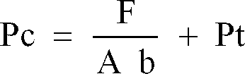
torque converter 2 exerted on the back pressure portion of the piston of the lock-upclutch 4 can be expressed by the following equation. Consequently, the hydraulic pressure Pt in thetorque converter 2 is canceled with the foregoing lock-up actual initial hydraulic pressure Ps.
- Now, it is assumed that an engine speed varies and thereby hydraulic pressure in the
torque converter 2 is varied from Pt to Pt'. At this moment, when the initial clutch pressure is represented by Pc' and the lock-up actual hydraulic pressure is represented by Ps', the following equations are established.
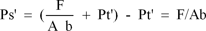

torque converter 2 is varied from Pt to Pt'. - Incidentally, reference has been made only to the actual initial hydraulic pressure Ps appearing at the time point of completion of the filling in the foregoing description. With respect to the lock-up pressure Pr (see Fig. 5) during the gradual increasing of hydraulic pressure after completion of the filling, the same relationship as described above is likewise established but the lock-up hydraulic pressure Pr is not affected by variation of the inner pressure Pt in the
torque converter 2. - Specifically, with the electronic type
pressure control valve 40 shown in Figs. 3 and 4, the inner pressure Pt of thetorque converter 2 is fed back to thehydraulic pressure 57 on thesolenoid 42 side to compensate the hydraulic pressure Pt in thetorque converter 2 active on the back pressure portion of the piston of the lock-upclutch 4. Thus, thepressure control valve 40 can suppress variation of the lock-up actual initial hydraulic pressure Ps due to variation of the hydraulic pressure Pt in thetorque converter 2. Therefore, there is no need of presetting the initial hydraulic pressure Pc to a higher level while taking account of variation of the hydraulic pressure Pt in the torque converter as is the case with the conventional control system. Thus, the lock-up actual initial hydraulic pressure Ps can assume a constant value at all times and the initial pressure Pc can be maintained at a lower pressure, if the solenoid driving current i at the time point of completion of the filling is determined to hold a constant low pressure. - This item (2) is concerned with timing control to be carried out when the lock-up
clutch 4 is turned off during speed changing. Here, operations of thecontroller 10 will be described with reference to a flowchart in Fig. 6 and and a plurality of time charts in Fig. 7. - The
controller 10 determines whether or not speed changing should be performed based on outputs from therotation sensor 6 and thethrottle quantity sensor 13 during running of the vehicle (step 200). - For example, when it is assumed that a first speed is selected by bringing the
speed changing clutch 21 shown in Fig. 2 in an operatively engaged state and thecontroller 10 has determined that a second speed should be selected at thestep 200, thecontroller 10 first actuates thepressure control valve 32 for the second speed clutch 22 (step 210). - When the
pressure control valve 32 is actuated (time t1 in Fig. 7), the clutch pack of the clutch 22 is brought in an empty state. This causes the clutch pressure of the clutch 22 to be held at a level of substantially zero until a certain period of time (filling time) tf elapses after thepressure control valve 32 is actuated, as shown in Fig. 7(b). - Next, the
controller 10 calculates a clutch hydraulic pressure P2 to be exerted on thespeed changing clutch 22 after the filling time tf elapses (step 220). - So-called speed changing shock takes place due to difference between output torque from the
transmission 3 just prior to speed changing and output torque from thetransmission 3 immediately after the speed changing. For the reason, an occurrence of the speed changing shock can be prevented by performing speed changing so as to eliminate the foregoing difference appearing between the foregoing two torques. - When it is assumed that the number of revolutions of the input shaft 1a of the
torque converter 2 is represented by n1 and the number of revolutions of theoutput shaft 2a of thetorque converter 2 shown in Fig. 1 is represented by n2, a primary coefficient (STP) and a torque ratio (ST) representative of performances of thetorque converter 2 can be calculated by deriving a ratio of the number of revolutions of the input shaft 1a to the number of revolutions of theoutput shaft 2a of thetorque converter 2, i.e., an e value which is equal to n2/n1. Since a torque converter input torque Tp is represented by the following equation,

- If the torque converter output torque Tt at the time point t1 of issuance of the speed changing command is derived, the torque TB on the output shaft of the
transmission 3 at the time point t1 can be derived in accordance with the following equation.
whole transmission 3. - On the other hand, a frictional torque of the clutch at the time point t2 of completion of the filling, i.e., a friction torque Tc on the
second speed clutch 22 to be next brought in an engaged state, at the time point t2 of completion of the filling is represented by the following equation.
- The friction torque Tc can be converted into a torque TA on the output shaft of the
transmission 3 at the time point t2 of completion of the filling by calculation to be carried out in accordance with the following Equation (16).
- To prevent variation of the torque during speed changing, it is required that the torque TB on the output shaft of the transmission just prior to speed changing represented by the Equation (14) is equal to the torque TA on the output shaft of the transmission at the time of completion of the filling. Hydraulic pressure in the clutch to be brought in an operatively engaged state (second speed clutch) when a requirement for the condition of


- It should be noted that the clutch friction coefficient in the above Equation (17) is a function of the number of revolutions of the clutch disc and therefore it is impossible to previously know it. However, the number of relative revolutions of the friction discs at the time of completion of the filling can be derived from the number n2 of revolutions of the output shaft of the torque converter detected by the
rotation sensor 7, a gear ratio of thetransmission 3 between before and after the speed changing and the number n3 of revolutions of the output shaft of the transmission detected by therotation sensor 8. This makes it possible to derive the clutch friction coefficient at the time of starting of the speed changing. - Referring to Fig. 6 again, at the
step 220, thecontroller 10 calculates hydraulic pressure P2 to be used for thespeed changing clutch 32 based on the Equation (17). - Next, the
controller 10 determines whether the filling time is terminated or not (step 230). In this case, the determination on termination of the filling time is made using a timer (not shown). Alternatively, in view of the phenomenon that flowing of hydraulic oil, e,g., in thespeed changing clutch 22 is substantially interrupted, termination of the filling time may be detected by a sensor which is disposed midway of a hydraulic pressure supplying passage to sense the foregoing phenomenon. - When the
controller 10 has determined at thestep 230 that the filling time is terminated, thecontroller 10 transmits a control signal to thepressure control valve 32 so as to allow the clutch hydraulic pressure P2 derived at thestep 220 to be exerted on the speed changing clutch 22 (step 240). Further, thecontroller 10 turns off thepressure control valve 31 operatively associated with thespeed changing clutch 21 for the first speed which has been currently brought in an operatively engaged state, at the time point t2 of termination of the filling time. In addition, thecontroller 10 outputs a lock-up stop command to thepressure control valve 40 connected to the lock-upclutch 4 at the time poit2 of termination of the filling time to turn off the lock-up clutch 4 (step 250). - After the time point t2, hydraulic pressure in the
speed changing clutch 22 is gradually increased until it is maintained at a preset pressure. - According to the control system of the present invention, as shown in Fig. 7(c), the
controller 10 turns off the lock-upclutch 4 at the time point t2 of termination of the filling time in the above-described manner. This makes it possible to avoid a malfunction that output torque from thetransmission 3 is reduced to zero due to arrangement of thetorque converter 2 for the period of filling time as is the case with the conventional control system which turns off the lock-up clutch at the time point t1 of outputting of a speed changing command. - Further, according to the control system of the present invention, as shown in Fig. 7(b), the clutch hydraulic pressure P2 derived at the
step 220 is exerted on thespeed changing clutch 22 for second speed at the time point t2 of completion of the filling. Thus, as shown in Fig. 7(d), torque on the output shaft of thetransmission 3 just before speed changing becomes equal to torque on the output shaft of the transmission at the time of completion of the filling, whereby an occurrence of the speed changing shock can be prevented effectively. - When the lock-up
clutch 4 is turned off at the time point t2, it seems that in practice a ratio of speed of a pump to speed of a turbine in thetorque converter 2 is momentally changed to 1 and thereby a moment in which no torque is transmitted exists. However, at the time point t2, the first speed clutch is turned off and the second speed clutch starts its operative engagement. Thus, since inertia energy in the transmission is consumed for operative engagement of the second speed clutch, in practice there exists no time in which torque transmission is interrupted. Since speed of the turbine in thetorque converter 2 is rapidly decreased due to load when the second speed clutch starts its operative engagement, torque is exchanged between the pump and the turbine in the torque converter immediately after the time point t2. - According to the control system of the present invention, as shown by a dotted line in Fig. 7(a), hydraulic pressure in the
speed changing clutch 21 for first speed is transiently decreased after thepressure control valve 22 is turned off. Accordingly, there arises an operative state that the second speed clutch 22 starts its operative engagement before thefirst speed clutch 21 becomes inoperative, and this may cause variation of torque to some extent. To prevent such phenomenon from taking place, as shown in Fig. 8(a), it will suffice that hydraulic pressure exerted on thefirst speed clutch 21 is previously decreased to a properly determined level of P1 for the period of time from the time point t1 when a speed changing command is issued till the time point t2 when the second speed clutch 22 starts operative engagement and then hydraulic pressure in thefirst speed clutch 21 is reduced to zero at the time point t2. It should be noted that the hydraulic pressure P1 may assume any value which assures that a value of output torque for the period of filling time between the time point t1 and the time point t2 shown in Fig. 7(b) can be maintained. A value indicative of the hydraulic pressure P1 can be derived in accordance with the Equations (14) and (16). - Fig. 9 illustrates a procedure of processings to be performed in the above-described manner. According to this procedure, a
step 225 is executed between thestep 220 and thestep 230 shown in Fig. 6. Specifically, at thestep 225, thecontroller 10 calculates a hydraulic pressure P1 to be exerted on thespeed changing clutch 21 which has been currently brought in an operatively engaged state, for the period of time between the time point t1 and the time point t2 and controls thepressure control valve 31 so as to allow hydraulic pressure in the clutch 21 to reach the calculated hydraulic pressure P1. - In this case, e.g., the following two methods of varying hydraulic pressure in the
speed changing clutch 21 by actuating thepressure control valve 31 are available. One of them is such that clutch hydraulic pressure is varied to the hydraulic pressure P1 immediately after issuance of a speed changing command, as represented by solid lines in Fig. 8(a). The other one is such that hydraulic pressure is gradually varied to the hydraulic pressure P1 after issuance of the speed changing command, as represented by a dotted line in Fig. 8(a). It should of course be understood that the hydraulic pressure P1 in thespeed changing clutch 21 is not necessarily identical to the hydraulic pressure P2 with which the speed changing clutch 22 starts its operative engagement. - According to this procedures of processings to be performed, the lock-up
clutch 4, of course, is turned off at the time point t2 when the filling time is terminated, as shown in Fig. 8(c). - In detail, according to the control system as shown in Figs. 8 and 9, hydraulic pressure in the clutch which has been brought in an operatively engaged state is decreased to an adequate level for the period of time until the filling time is terminated and the hydraulic pressure in the clutch is then reduced to zero when the filling time is terminated, whereby variation of torque caused when a next clutch starts its operative engagement can be prevented with higher accuracy.
- It should be noted that when the
controller 10 performs calculation for the Equation (17), output torque Tt from thetorque converter 2 may be derived based on output torque from theengine 1 utilizing the previously known performances of output from theengine 1 or it may be derived directly by using a torque sensor. - The item (3) is concerned with a control for modulating hydraulic pressure when the number of revolutions of the engine exceeds the minimum number of revolutions of the engine required for lock-up engagement after the vehicle starts its forward movement in response to a command issued by actuation of the
shift lever 16. This control will be described below with reference flowcharts in Figs. 10(a) and (b) and a plurality of time charts in Fig. 11 illustrating characteristics relative to a command indicative of hydraulic pressure for locking-up or the like issued as time elapses. - After the vehicle starts its forward movement, the
controller 10 measures the number n1 of revolutions of the engine based on output from theengine rotation sensor 6. When the number n1 of revolutions of the engine exceeds the minimum number nr of revolutions of the engine (see Fig. 11(b)) required for locking-up (step 300), a trigger command indicative of high pressure is inputted in thesolenoid 42 of thepressure control valve 40 for the lock-upclutch 4 for a predetermined period of time, whereby high pressure hydraulic oil is supplied to the lock-upclutch 4 to promote a processing of filling (step 310). Thereafter, to fully complete the filling, a command indicative of hydraulic pressure is lowered to a value corresponding to hydraulic pressure (Pt + ) higher than the hydraulic pressure in thetorque converter 2 and this value is then maintained for a predetermined period of time (steps 320 and 330). In this case, the reason why the lock-upclutch 4 is supplied with hydraulic pressure higher than the hydraulic pressure in thetorque converter 2 in that way consists in that the hydraulic pressure in thetorque converter 2 is exerted on the back pressure portion of a piston of the lock-upclutch 4. In case where the above-described structure is not employed, it is natural that there is no need of taking account of the above-described arrangement. Since the hydraulic pressure in thetorque converter 2 is substantially in proportion to the number of revolutions of the engine, it can be calculated based on outputs from theengine rotation sensor 6 and other sensors. Incidentally, in case where the number of revolutions of the engine varies few, a predetermined intensity of hydraulic pressure (corresponding to a value of the upper limit of variation) may be exerted on the lock-upclutch 4. - Next, when the
controller 10 confirms completion of the filling by carrying out control as time elapses or on the basis of outputs from a suitable filling detecting sensor and other sensors, thecontroller 10 gradually increases a command indicative of hydraulic pressure to be supplied to thepressure control valve 40 so as to allow the lock-upclutch 4 to be brought in an operatively engaged state, whereby hydraulic pressure in the lock-upclutch 4 can be increased gradually. At this moment, a gradient of increasing of hydraulic pressure varies in dependence on an extent S of opening of the throttle and the weight I of the vehicle body. Usually, lock-up engagement at the time of starting of forward movement of the vehicle is accomplished at the minimum speed stage. When the lock-up engagement is accomplished at other speed stage, a speed reduction ratio is added to the aforementioned parameters and then a build-up rate is properly varied in dependence on these parameter (vehicle weight, extent of opening of throttle and gear ratio) (step 340). - Shock caused by speed changing on a gear type transmission is evaluated using a jerk value J which is defined in accordance with the following equation.

- J :
- jerk value
- α :
- acceleration of vehicle body
- K :
- conversion coefficient
- G :
- constant relative to speed reduction ratio
- I :
- weight of vehicle (weight of vehicle body + weight of load placed on vehicle body)
- µ :
- friction coefficient of clutch disc
- P :
- hydraulic pressure in clutch
- The constant G relative to a speed reduction ratio is determined in dependence on the current speed stage but it includes a coefficient suggestive of the number of clutch plates superposed one above another and an area of respective clutch plate at individual speed stage. Therefore, this constant G has a value which differs to some extent depending on respective speed stage. Of course, in case where the number of clutch plates superposed one above another and an area of each clutch plate are same at respective speed stage, the constant G designates a speed reduction ratio itself.
- The second term P

- Description will be hereinafter made while not taking the second term into account.
- For the above-described reason, the jerk value in the Equation (18) may be expressed by the following equation.

- A resolution dp/dt to be derived based on the Equation (19) will be represented as follows.

- Referring to the Equation (20), since K and µ are a known value, respectively, it will suffice that only I, J and G are derived.
- In practice, I, i.e., the weight of the vehicle can be obtained from an output from the
vehicle weight sensor 14 and G, i.e., the constant relative to a speed reduction ratio can be obtained from the speed reduction ratio itself. On the other hand, J, i.e., the jerk value represents a value indicative of shock to be used as a target. This value is determined by a magnitude of load (a smaller value is preferable for light load and a larger value is preferable for heavy load). Since load exerted on the vehicle body can not practically be measured but it is in proportion to power generated by the engine, the above target jerk value J can be determined based on the current extent of opening of the throttle. Namely, the jerk value J can be determined based on an output from thethrottle quantity sensor 13. Incidentally, the jerk value J can be changed in proportion to the output from thethrottle quantity sensor 13. - In this manner, the
controller 10 measures the extent of opening of the throttle, the vehicle weight and the gear ratio and calculates the optimum build-up rate dp/dt so as to gradually increase hydraulic pressure based on the calculated dp/dt. Alternatively, dp/dt may previously be stored in a memory of thecontroller 10 using the extent of opening of the throttle, the vehicle weight and the gear ratio as variables, so as to allow dp/dt corresponding to detected values of these variables to be read from the memory, as required. Additionally, data derived from actual measurements conducted with an actual vehicle may be used: - After the hydraulic pressure is gradually increased, the
controller 10 measures an e value of the torque converter 2 (step 360) (the e value is represented n2/n1, wherein n1 designates the number of revolutions of an input shaft of thetorque converter 2 and n2 designates the number of revolutions of an output shaft of the torque converter 2). When the e value becomes "1" or a predetermined value "Eo" very near to 1 (see Fig. 11(c)), the gradual increasing of hydraulic pressure is terminated (step 390). If the hydraulic pressure in the lock-upclutch 4 exceeds the preset pressure Pa indicative of the upper limit during the gradual increasing of hydraulic pressure before the e value reaches "1" or the preset value Eo (see Fig. 11(a)), thecontroller 10 carries out control such that the hydraulic pressure in the lock-upclutch 4 is maintained at the upper limit indicative of the preset pressure Pa for a certain period of time until the e value reaches Eo (steps 370 and 380). It should be added that once the e value is obtained, the number of revolutions of the output shaft of thetorque converter 2 may be derived using output from the transmission outputshaft rotation sensor 8 and the gear ration. - The item (4) is concerned with control to be carried out during normal running of the vehicle after speed changing or starting of forward movement of the vehicle.
- When control for gradually increasing hydraulic pressure is terminated, the
controller 10 carries out control such that hydraulic pressure in thetorque converter 2 is reduced to a value corresponding to output torque from the engine or a value Pβ appreciably larger than the first-mentioned value (see Fig. 11(a)). - Specifically, the
controller 10 determines at astep 400 whether speed changing should be effected or not. Thereafter, when thecontroller 10 determined that speed changing should not be effected, it calculates torque T generated by theengine 1 based on the output S from thethrottle quantity sensor 13 and the output n1 from theengine rotation sensor 6, as long as the number n1 of revolutions of the engine is decreased smaller than the minimum number n2 of revolutions of the engine required for establishing a lock-up state (step 430). - As shown in Fig. 12, the torque T outputted from the engine is closely related to the number of revolutions of the
engine 1 and the extent of opening of the throttle, and various values of torque T corresponding to respective values of these parameters are previously stored in the memory of thecontroller 10. Thus, the current engine torque T can be derived by reading from the memory the torque value corresponding to detection outputs from theengine rotation sensor 6 and thethrottle quantity sensor 13. In practice, since values completely coinciding with the previously stored parameter values are not necessarily inputted from the respective sensors, intermediate adequate values are derived using a processing of interpolation or the like. Then, thecontroller 10 controls clutch hydraulic pressure such that the torque transmitted by the lock-upclutch 4 coincides with the engine output torque T derived from the number of revolutions of the engine and the extent of opening of the throttle or the torque transmitted from the lock-upclutch 4 assumes a value appreciably larger than the engine output torque T. - Here, the torque T' transmitted from the lock-up
clutch 4 can be expressed by the following equation.
- K :
- clutch coefficient
- µ(v) :
- friction coefficient of clutch
- P :
- clutch pressure
- Namely, the
controller 10 derives the engine torque T from outputs from thethrottle quantity sensor 13 and theengine rotation sensor 6, converts the derived torque value T or the value appreciably larger than the latter into a clutch pressure P in accordance with the Equation (21) (step 440) and then delivers a hydraulic pressure command corresponding to the converted clutch pressure P to the pressure control valve (step 450). - During running of the vehicle, the engine output torque T varies as shown in Fig. 13(b). According to the above-described control, however, since the vehicle runs while the lock-up clutch pressure is reduced to the converted value derived by converting the engine output torque into hydraulic pressure (represented by a dotted line in Fig. 13(a)) or to hydraulic pressure appreciably larger than the converted value (represented by a solid line in Fig. 13(a)), variation of output on the transmission output shaft due to variation of engine output torque can be reduced, whereby variation of output of the transmission output shaft can be suppressed as shown in Fig. 13(d), even when a large magnitude of variation is caused with the number of revolutions of the engine as shown in Fig. 13(c). Accordingly, the minimum number nr of revolutions of the engine relative to the lock-up engagement can be set to the lower speed side than the conventional apparatus, resulting in a property of fuel consumption being improved.
- Incidentally, according to the above-described embodiment, the clutch hydraulic pressure is reduced to a level of the value Pβ corresponding to the engine output torque without delay when the e value of the torque converter reaches the present value Eo. Alternatively, the clutch hydraulic pressure may be reduced to a level of the foregoing value Pβ after a predetermined period of time elapses, after hydraulic pressure is gradually increased and then the corresponding time measurement is carried out.
- Control relative to the item (5) is carried out during speed changing for the vehicle.
- During speed changing with the conventional apparatus, to reduce a load to be carried by the speed changing clutch, the speed changing clutch is brought in operative engagement after the lock-up clutch is completely released from the operative state. According to the present invention, however, the lock-up clutch is not, completely released from the operative state during the speed changing for the vehicle but half lock-up control is executed for gradually increasing hydraulic pressure after possibly low hydraulic pressure above the hydraulic pressure in the torque converter is maintained. Accordingly, during a controlling operation according to the present invention, there does not exist filling time required for fully filling the clutch pack with hydraulic oil.
- Fig. 14 is a diagram which illustrates variation of characteristics of a command indicative of lock-up hydraulic pressure during the speed changing of the vehicle as time elapses.
- At the time of speed changing, the
controller 10 calculates the pressure Pt in the torque converter based on an output from the engine rotation sensor 6 (step 460 in Fig. 10(b)), reduces the hydraulic pressure in the lock-upclutch 4 to a level of (pt + β) which represents a predetermined pressure β with the calculated value Pt of pressure in thetorque converter 2 added thereto and then holds this value of hydraulic pressure (Pt + β) for a short period of time (step 470). - While the foregoing operative state is maintained, the
controller 10 determines a build-up starting time point ts when gradual increasing of hydraulic pressure starts (step 480). To determine a timing of the build-up is started, the following three methods have been proposed. - (a) Method of setting an interval time
According to this method, an optimum interval time T1 is previously derived by simulation, actual vehicle test or the like using each speed stage and engine power (represented by the extent of opening of the throttle) as parameters (see Fig. 14) and then it is stored in the memory of thecontroller 10 in the form of a map, as shown in Fig. 15. During the speed changing of the vehicle, the interval time T1 corresponding to the output from thethrottle quantity sensor 13 and the current speed stage is read from the memory, and build-up of the hydraulic pressure is started when the interval time T1 elapses. - (b) Method of sensing the number of relative revolutions of the clutch
According to this method, the number of relative revolutions of the clutch (which is equal to n3 · G - n2, where G designates a gear ratio) is derived based on the output n2 from the inputshaft rotation sensor 7 and the output n3 from theoutput shaft sensor 8 of the transmission, and when the calculated value is reduced to zero or almost zero as shown in Fig. 16, this is identified as a build-up starting time. - (c) Method of sensing the e value of the torque converter
According to this method, the e value of the torque converter (which is equal to n2/n1) is calculated based on the output from theengine rotation sensor 6 and the input shaft sensor 7 (or theoutput shaft sensor 8 of the transmission), and when this e value is in excess of a certain set value E1 as shown in Fig. 17, this term is identified as a build-up starting time. - Among the above-described three methods, the method (a) is most simple and practical. To carry out the methods (b) and (c), a rotation sensor is required for each of them but the method (b) is a method advantageously employable for improving a characteristic of acceleration and the method (c) is a method advantageously employable for reducing of shock caused by speed changing.
- When the
controller 10 determines using any one of the aforementioned methods that the build-up starting time ts is reached (step 490), it measures the extent of opening of the throttle S, the vehicle weight I and the gear ratio, calculates an optimum build-up rate dp/dt based on the measured values in accordance with the above Equation (20) (step 500) and then gradually increases hydraulic pressure in response to the calculated value dp/dt in the same manner as the aforementioned controlling operation at the time of starting of forward movement of the vehicle (step 510). The operation of gradually increasing the hydraulic pressure is interrupted when the e value of the torque converter reaches "1" or the set value "Eo" which is very near to 1 and, when the clutch pressure exceeds the upper limit set pressure Pα before the e value reaches "1" or the set pressure value Eo, the clutch pressure is maintained at a level of the upper limit set value Pα in the same manner at the time of starting of forward movement of the vehicle (steps 520 to 550). Thereafter, as the vehicle runs, thecontroller 10 carries out control as described above in the item (4) so as to allow the lock-up pressure to assume a value corresponding to the engine output torque T. - The item (6), i.e., the structure as shown in Fig. 18 is such that a flow
rate detecting valve 60 is disposed in addition to the system structure as shown in Fig. 3. The flowrate detecting valve 60 is provided with afilling detecting sensor 61. Incidentally, same or similar other structural components as those in Fig. 3 are represented by same reference numerals. Thus, repeated description will not be required. - The electronic
type control valve 40 is a proportional control valve adapted to be actuated in response to an electrical command outputted from thecontroller 10 in the same manner as mentioned above. To prevent the lock-up actual initial hydraulic pressure Ps from varying due to variation of the hydraulic pressure in the torque converter, the hydraulic pressure in the torque converter is fed back to theproportional solenoid 42 side of thepressure control valve 20 via ahydraulic passage 41. - The flow
rate detecting valve 60 is disposed so as to allow hydraulic oil to be fed to the lock-upclutch 4 at a high flow rate during the filling operation to shorten a period of time required for the filling operation. The flowrate detecting valve 60 is provided with afilling detecting sensor 61 for detecting completion of the filling operation based on movement of the spool in the flowrate detecting valve 60. - Fig. 19 is a schematic sectional view which illustrates by way of example the inner structure of the
pressure control valve 40, the flowrate detecting valve 60 and thefilling detecting sensor 61. - With the structure as shown in Fig. 19, hydraulic oil delivered from the
hydraulic pump 15 is introduced into the flowrate detecting valve 60 via aninput port 62 so that it is supplied to the lock-upclutch 4 via anoutput port 63. At this moment, aport 64 is kept closed. - The electronic type
pressure control valve 40 includes aspool 65 of which right-hand end comes in contact with aplunger 66 of theproportional solenoid 42 and of which left-hand end is resiliently supported by aspring 67. Hydraulic pressure in ahydraulic chamber 70 is introduced into ahydraulic chamber 69 which is defined by thespool 69 and thepiston 68. Further, thepressure control valve 40 includes ahydraulic chamber 71 on theproportional solenoid 42 side into which the hydraulic pressure in the torque converter is introduced via ahydraulic passage 41. - The flow
rate detecting valve 60 includes aspool 72 which is formed with anorifice 73 on theoutput port 63 side. The left-hand end surface of thespool 72 is resiliently supported by aspring 74 and hydraulic pressure before theorifice 73 is delivered to ahydraulic chamber 75 via ahydraulic passage 76. - An electromagnetic pick-
up 61 serving as a filling detecting sensor is attached to the right-hand end surface of the flowrate detecting valve 60 with ahousing cover 77 interposed therebetween. Thecontroller 10 determines completion of the filling when the pick-up 61 detects movement of thespool 72 of the flowrate control valve 60. Namely, voltage induced by the pick-up 61 varies as thespool 72 is displaced toward or away from the pick-up 61, whereby movement of thespool 72 can be detected by detecting variation of the induced voltage. - When it is required that the lock-up
clutch 4 is brought in an operatively engaged-state with the combined structure of thepressure control valve 40 and the flowrate detecting valve 60 as shown in Figs. 18 and 19, thecontroller 10 turns on thesolenoid 42 of thepressure control valve 40. This permits thespool 61 of thepressure control valve 40 to be displaced in the leftward direction, whereby hydraulic oil delivered from thehydraulic pump 15 flows in thepressure control valve 40 via theinput port 62 and thehydraulic passage 78. Then, the hydraulic oil which has flowed in thepressure control valve 40 flows further in the flowrate detecting valve 60 via ahydraulic passage 70 and a port 79 so that it is delivered to the lock-upclutch 4 via theorifice 74 in thespool 72 and theoutput port 63. The hydraulic oil in the port 79 is introduced into thehydraulic chamber 75 via thehydraulic passage 76 in thespool 72. - This causes a differential pressure to be generated across the
orifice 73, whereby thespool 72 is displaced in the leftward direction under the effect of the differential pressure until the flowrate detecting valve 60 is opened. Consequently, pressurized hydraulic oil which has flowed in theinput port 62 enters directly the port 79 and then it is delivered to the lock-upclutch 4 via theorifice 73. Supplying of hydraulic oil to the lock-upclutch 4 via the flowrate detecting valve 60 continues until the clutch pack is fully filled with hydraulic oil. - As shown in Fig. 5, hydraulic pressure in the lock-up
clutch 4 is kept at a level of almost zero for a period of filling time tf until the clutch pack is filled with hydraulic oil. On completion of the filling, it is raised up to the initial pressure Pc. - When the clutch pack is fully filled with hydraulic oil, the filling operation is ended and no hydraulic oil flows any more with the result that the differential pressure across the
orifice 73 disappears. This allows thespool 72 of the flowrate detecting valve 60 to be displaced by restorable force of thespring 74 until the flowrate detecting valve 60 is restored to the closed state. - Namely, when the clutch pack is fully filled with hydraulic oil, the
spool 72 of the flowrate detecting valve 60 is restored to the position as shown in Fig. 19 under the effect of restorable force of thecoil 74. Thus, completion of the filling can exactly be detected by detecting completion of the return movement of thespool 72 by the pick-up 61. - The detection signal of the pick-
up 61 is inputted into thecontroller 10. After thecontroller 10 detects completion of the filling in response to the input signal, hydraulic pressure in the lock-upclutch 4 is gradually increased by gradually increasing a magnitude of electricity to be fed to thesolenoid 42. - Namely, with the combined structure of the
pressure control valve 40 and the flowrate detecting valve 60 as shown in Figs. 18 and 19, the pressure Pt in thetorque converter 2 is fed back to thehydraulic chamber 71 on thesolenoid 42 side of thepressure control valve 40 to cancel the pressure Pt in thetorque converter 2 which is exerted on the back pressure portion of the piston of the lock-upclutch 4, whereby variation of the lock-up actual initial hydraulic pressure Ps due to variation of the hydraulic pressure in thetorque converter 2 can be suppressed. Accordingly, the lock-up actual initial pressure Ps can always assume a constant value by holding the solenoid driving current i constant at the time of completion of the filling. With this combined structure, arrangement of the flowrate detecting valve 60 makes it possible to supply the lock-upclutch 4 with hydraulic oil at a high flow rate. Since the time of completion of the filling can exactly be determined by sensing movement of thespool 72 of the flowrate detecting valve 60 using the pick-up 61, hydraulic pressure in the lock-upclutch 4 at the time of completion of the filling, i.e., the initial pressure in the clutch can be reduced almost to a level of hydraulic pressure in thetorque converter 2, whereby shock caused when the lock-upclutch 4 is brought in an operatively engaged state with the initial pressure can be reduced remarkably. - Incidentally, with the combined structure as shown in Fig. 19, completion of the filling is determined by detecting movement of the
spool 72 of the flowrate detecting valve 60 using the pick-up 61. Alternatively, filling detecting means having any other structure may be employed, provided that it is proven that completion of the filling is detected based on movement of thespool 72 of the flowrate detecting valve 60. For example, completion of the filling may be detected in such a manner that a piston disposed leftward of thespool 72 is resiliently supported by thespring 74 and displacement of the piston toward and away from thehousing cover 77 is electrically detected as thespool 72 moves. - The item (7) is concerned with a structure for a conventional hydraulic control system as shown in Fig. 25 having a
solenoid valve 80 for the purpose of drainage added thereto, as shown in Fig. 20. Same or similar structural components as those in Fig. 25 are identified by same reference numerals. Thus, their repeated description will not be required. - The
solenoid valve 80 serves to bring hydraulic oil in the load piston control chamber of amodulation valve 110 to a drain port. With such a control system, hydraulic pressure in the lock-upclutch 4 is controlled by operation of themodulation valve 110, thesolenoid valve 110 and the solenoid valve 80 (hereinafter referred to as a drain valve). - Figs. 21 and 22 illustrate by way of example the inner structure of these three valves, respectively. As shown in Figs. 21 and 22, a load
piston control chamber 81 for allowing hydraulic pressure to be exerted on apiston 139 of themodulation valve 110 is communicated with a drain port via ahydraulic passage 82 and thedrain valve 80 so that thedrain valve 80 determines whether hydraulic oil should be drained or not. - Operations of the
solenoid valve 120, themodulation valve 110 and thedrain valve 80 as constructed in the above-described manner during speed changing will be described below with reference to Fig. 23 which shows a plurality of time charts as well as Fig. 1. - Fig. 23(a) shows a command voltage to be given to the
solenoid valve 120 by thecontroller 10, Fig. 23(b) shows a command voltage to be given to thedrain valve 80, Fig. 23(c) shows hydraulic pressure PL in thepiston chamber 81, Fig. 23(d) shows hydraulic pressure Pv at an outlet port of themodulation valve 110, Fig. 23(e) shows hydraulic pressure in the lock-upclutch 4, Fig. 23(f) shows a stroke of thepiston 139 and Fig. 23(g) shows torque on the output shaft of the transmission. - While the number n1 of revolutions of the engine exceeds the minimum number of revolutions of the lock-up
clutch 4, thecontroller 10 feeds thesolenoid valve 120 with a command voltage so as to allow thesolenoid valve 120 to be shifted to an "ON" state before speed changing, as shown in Fig. 23(a). When speed changing is commanded while the foregoing state is maintained (time t1), thecontroller 10 feeds thedrain valve 80 with a command voltage represented by "ON" (see Fig. 23(b)), whole the command voltage to thesolenoid valve 120 is left unchanged at the "ON" state (see Fig. 23(a)). Thecontroller 10 holds thedrain valve 80 at the "ON" state for the period of lock-up delay time T1, and after the delay time T1 elapses, thecontroller 10 reduces the command voltage to thedrain valve 80 to a level of zero (time t2). As a result, thedrain valve 80 is shifted to the drain side so that hydraulic oil in the loadpiston control chamber 81 is quickly drained via thehydraulic passage 82. Thus, theload piston 139 is returned from the position shown in Fig. 22 to the position shown in Fig. 21, i.e., the position where aspring 133 is initially accommodated in the load piston 139 (Fig. 23(f), time t1) with the result that hydraulic pressure Pv at an outlet port of themodulation valve 110 is reduced to the initial pressure Po (which is equal to Kx/S1, where K designates a spring constant, x designates an initial displacement and S1 designates a pressure receiving surface area of the piston 131) as shown in Fig. 23(d), and the hydraulic pressure Pv is held at the initial pressure Po for the period of lock-up delay time. Accordingly, hydraulic pressure in the lock-up clutch varies in the substantially same manner as the hydraulic pressure Pv at the outlet port of themodulation valve 110, as shown in Fig. 23(e). - When the lock-up delay time elapses, the
controller 10 reduces the command voltage to thedrain valve 80 to zero to close the drain valve 80 (time t2). Consequently, the hydraulic oil which has entered the loadpiston control chamber 81 via anorifice 138 is intercepted in the loadpiston control chamber 81, whereby theload piston 139 is displaced in the rightward direction. As the load piston moves in the rightward direction as shown in Fig. 22, the hydraulic pressure in the lock-upclutch 4 is increased gradually. Thereafter, when theload piston 139 collides with a stopper, gradual increasing of the hydraulic pressure is stopped to assume a certain value. Thereafter, this value of hydraulic pressure is maintained. - Namely, according to the control system, the hydraulic pressure in the lock-up clutch is not completely released during the speed changing but the
controller 10 carries out half lock-up control as shown Fig. 11 and Fig. 14 wherein hydraulic pressure in the hydraulic clutch is reduced to the initial pressure Po higher than the pressure Pt in the torque converter. As a result, hydraulic pressure in the lock-up clutch can be built up from the value of initial hydraulic pressure corresponding to the hydraulic pressure at the time of completion of the filling in a good timing relationship. Thus, a characteristic of acceleration can be improved and shock appearing when the lock-up clutch is brought in an operatively engaged state can be reduced substantially, as shown in Fig. 23(g). - The reason why the lock-up clutch is released during the speed changing consists in reduction of load to be carried by the speed changing clutch. According to this control system, however, thermal load to be carried by the clutch can be distributed to the speed changing clutch and the lock-up clutch by reducing torque to be transmitted via the lock-up clutch (i.e., by bringing the lock-up
clutch 4 in a slippery state), resulting in durability of these clutches being improved. - Incidentally, the timing for starting the gradual increase of hydraulic pressure in the lock-up clutch (time t2) can be determined in accordance with one of the following three methods.
- (a) Method of setting interval time
- (b) Method of sensing the number of relative revolutions of a clutch
- (c) Method of sensing an e value of the torque converter
- A build-up rate during gradual increasing of hydraulic pressure may be varied in dependence on the extent of opening of the throttle, the vehicle weight (weight of the vehicle body + quantity of load placed on the vehicle body) and the gear ratio of the transmission, as mentioned above. Variable control for determining such a build-up rate can easily be realized by carrying out duty control as shown in Fig. 24 in response to a voltage command to be given to the
drain valve 80. Here, duty ratios of 0 %, 50 % and 100 % are shown in Fig. 24. - The present invention is advantageously employable for a speed changing unit including a lock-up clutch by way of which the input shaft of a torque converter is operatively connected to the output shaft of the torque converter which is installed on a construction machine such as a truck, a wheel loader or the like vehicle.
Claims (2)
- An apparatus for controlling a lock-up clutch comprising;a pressure control valve connected to said lock-up clutch to generate hydraulic pressure in the lock-up clutch in response to an inputted electrical command,first detecting means for detecting a quantity of throttle,second detecting means for detecting weight of a vehicle,third detecting means for sensing a gear ratio of the transmission, said gear ratio being determined depending on the speed stage, andcontrolling means for calculating acceleration of increasing of hydraulic pressure during the gradual increasing of hydraulic pressure based on detection outputs from said first, second and third detecting means so as to allow an electrical command corresponding to the calculated acceleration of increase of hydraulic pressure to be inputted into said pressure control valve.
- An apparatus for controlling a lock-up clutch as claimed in claim 1, wherein said controlling means includes a memory in which a value of acceleration of increase of hydraulic pressure corresponding to the quantity of throttle, weight of the vehicle and the gear ratio is previously stored and an electrical command to be inputted into the pressure control valve is created based on data read from said memory.
Applications Claiming Priority (11)
| Application Number | Priority Date | Filing Date | Title |
|---|---|---|---|
| JP12731887A JPH07113409B2 (en) | 1987-05-22 | 1987-05-22 | Lockup clutch hydraulic controller |
| JP127319/87 | 1987-05-22 | ||
| JP12731987A JPS63293360A (en) | 1987-05-22 | 1987-05-22 | Lock-up clutch hydraulic control valve |
| JP127318/87 | 1987-05-22 | ||
| JP135784/87 | 1987-05-29 | ||
| JP62135784A JP2772636B2 (en) | 1987-05-29 | 1987-05-29 | Lock-up clutch hydraulic control device |
| JP62135783A JP2796800B2 (en) | 1987-05-29 | 1987-05-29 | Lock-up clutch hydraulic control device |
| JP135783/87 | 1987-05-29 | ||
| JP13583887A JPH081248B2 (en) | 1987-05-30 | 1987-05-30 | Lockup clutch hydraulic controller |
| JP135838/87 | 1987-05-30 | ||
| EP95109730A EP0677685B1 (en) | 1987-05-22 | 1988-05-23 | Apparatus and method for controlling lock-up clutch |
Related Parent Applications (3)
| Application Number | Title | Priority Date | Filing Date |
|---|---|---|---|
| EP95109730A Division EP0677685B1 (en) | 1987-05-22 | 1988-05-23 | Apparatus and method for controlling lock-up clutch |
| EP88904620.7 Division | 1988-12-06 | ||
| EP95109730.2 Division | 1995-06-22 |
Publications (2)
| Publication Number | Publication Date |
|---|---|
| EP0801253A2 true EP0801253A2 (en) | 1997-10-15 |
| EP0801253A3 EP0801253A3 (en) | 1998-03-04 |
Family
ID=27527134
Family Applications (3)
| Application Number | Title | Priority Date | Filing Date |
|---|---|---|---|
| EP88904620A Expired - Lifetime EP0373219B1 (en) | 1987-05-22 | 1988-05-23 | Lockup clutch control apparatus and method |
| EP97201563A Ceased EP0801253A3 (en) | 1987-05-22 | 1988-05-23 | Apparatus for controlling lock-up clutch |
| EP95109730A Expired - Lifetime EP0677685B1 (en) | 1987-05-22 | 1988-05-23 | Apparatus and method for controlling lock-up clutch |
Family Applications Before (1)
| Application Number | Title | Priority Date | Filing Date |
|---|---|---|---|
| EP88904620A Expired - Lifetime EP0373219B1 (en) | 1987-05-22 | 1988-05-23 | Lockup clutch control apparatus and method |
Family Applications After (1)
| Application Number | Title | Priority Date | Filing Date |
|---|---|---|---|
| EP95109730A Expired - Lifetime EP0677685B1 (en) | 1987-05-22 | 1988-05-23 | Apparatus and method for controlling lock-up clutch |
Country Status (5)
| Country | Link |
|---|---|
| US (2) | US5417622A (en) |
| EP (3) | EP0373219B1 (en) |
| AU (2) | AU624073B2 (en) |
| DE (2) | DE3854942T2 (en) |
| WO (1) | WO1988009454A1 (en) |
Families Citing this family (53)
| Publication number | Priority date | Publication date | Assignee | Title |
|---|---|---|---|---|
| AU624073B2 (en) * | 1987-05-22 | 1992-06-04 | Kabushiki Kaisha Komatsu Seisakusho | Lockup clutch control apparatus and method |
| US5213186A (en) * | 1990-11-30 | 1993-05-25 | Toyota Jidosha Kabushiki Kaisha | Control system and method for automatic transmission |
| DE4393919D2 (en) * | 1992-08-21 | 1995-10-19 | Luk Getriebe Systeme Gmbh | Method for controlling a torque transmission system |
| JP3422519B2 (en) * | 1993-05-14 | 2003-06-30 | ジヤトコ株式会社 | Lockup control device for automatic transmission |
| JP3353430B2 (en) * | 1993-12-22 | 2002-12-03 | 日産自動車株式会社 | Lockup control device for automatic transmission |
| JP3092426B2 (en) * | 1993-12-27 | 2000-09-25 | 日産自動車株式会社 | Lockup control device for automatic transmission |
| JP3211630B2 (en) * | 1994-07-20 | 2001-09-25 | トヨタ自動車株式会社 | Slip control device for vehicle lock-up clutch |
| US5634867A (en) * | 1994-09-19 | 1997-06-03 | Eaton Corporation | Main clutch reengagement control for a double clutch downshift |
| JP3384157B2 (en) * | 1994-12-27 | 2003-03-10 | 日産自動車株式会社 | Lockup control device for torque converter |
| JP3653839B2 (en) * | 1995-01-31 | 2005-06-02 | マツダ株式会社 | Hydraulic control device for automatic transmission |
| JPH09105454A (en) * | 1995-10-12 | 1997-04-22 | Jatco Corp | Control method and device for automatic transmission |
| US5916293A (en) * | 1996-01-25 | 1999-06-29 | Nissan Motor Co., Ltd. | Lockup control apparatus |
| JP3317133B2 (en) * | 1996-04-17 | 2002-08-26 | トヨタ自動車株式会社 | Control device for vehicle lock-up clutch |
| WO1998001687A1 (en) * | 1996-07-08 | 1998-01-15 | Komatsu Ltd. | Control device and control method for transmission with clutch |
| JPH10122355A (en) * | 1996-10-14 | 1998-05-15 | Denso Corp | Control device and control method for automatic transmission with lock up clutch |
| IT1291497B1 (en) * | 1997-02-04 | 1999-01-11 | Magneti Marelli Spa | METHOD AND CONTROL DEVICE OF A VEHICLE CLUTCH |
| DE19705694C1 (en) * | 1997-02-14 | 1998-05-14 | Zahnradfabrik Friedrichshafen | Motor vehicle torque converter switching control method |
| US6077188A (en) * | 1997-12-01 | 2000-06-20 | Aisin Seiki Kabushiki Kaisha | Lock-up control method of automatic transmission |
| US5941358A (en) * | 1997-12-16 | 1999-08-24 | Caterpillar Inc. | End-of-fill detector arrangement for a fluid actuated clutch |
| DE19951946A1 (en) * | 1998-11-03 | 2000-05-04 | Luk Getriebe Systeme Gmbh | Method of running a motor vehicle that uses hydraulic fluid pressure to generate a characteristic clutch curve. |
| US6223111B1 (en) * | 1999-04-08 | 2001-04-24 | Caterpillar Inc. | Method and apparatus for generating velocity commands for a continuously variable transmission |
| US6295497B1 (en) | 1999-10-27 | 2001-09-25 | Caterpillar Inc. | Method and apparatus for adaptively shifting ranges in a continuously variable transmission |
| SE515747C2 (en) * | 1999-12-13 | 2001-10-01 | Volvo Lastvagnar Ab | Hydraulic control system for a vehicle transmission |
| US6260440B1 (en) | 1999-12-17 | 2001-07-17 | Caterpillar Inc. | Method and apparatus for shifting ranges in a continuously variable transmission |
| JP4078789B2 (en) * | 2000-04-21 | 2008-04-23 | アイシン・エィ・ダブリュ株式会社 | Lock-up control device for automatic transmission |
| US6402660B1 (en) | 2000-09-26 | 2002-06-11 | Caterpillar Inc. | Apparatus and method for adaptively shifting between ranges in a continuously variable transmission |
| US6679806B2 (en) * | 2001-01-03 | 2004-01-20 | S & S Trust | Soft shift system and method |
| JP4201111B2 (en) * | 2001-10-31 | 2008-12-24 | アイシン・エィ・ダブリュ株式会社 | Automatic transmission lockup control device |
| US7117881B2 (en) * | 2003-02-11 | 2006-10-10 | Luk Lamellen Und Kupplungsbau Beteiligungs Kg | Control system |
| US7220216B2 (en) * | 2003-10-29 | 2007-05-22 | Aisin Seiki Kabushiki Kaisha | Lock-up clutch control device |
| JP4054778B2 (en) * | 2004-03-31 | 2008-03-05 | ジヤトコ株式会社 | Control device for automatic transmission |
| US7556586B2 (en) * | 2004-07-28 | 2009-07-07 | Komatsu Ltd. | Shift control device and shift control method for vehicle |
| JPWO2006022154A1 (en) * | 2004-08-23 | 2008-05-08 | 株式会社小松製作所 | Shift control device and shift control method for work vehicle |
| EP1717473B1 (en) * | 2005-04-25 | 2009-09-02 | HOERBIGER Antriebstechnik GmbH | Activation control device for the clutch packs of a hydraulic double clutch |
| US7398705B2 (en) * | 2005-12-12 | 2008-07-15 | Deere & Company | Method for the control of a gearbox arrangement |
| US8322252B2 (en) * | 2006-09-29 | 2012-12-04 | Caterpillar Inc. | Step-change transmission having charge and variable displacement pumps |
| US7604566B2 (en) * | 2007-03-02 | 2009-10-20 | Honda Motor Co., Ltd. | System and method of controlling a torque converter lockup clutch |
| DE102008001841A1 (en) * | 2008-05-19 | 2009-11-26 | Zf Friedrichshafen Ag | A method for driving a lock-up clutch in a hydrodynamic torque transmission device |
| DE102008043107A1 (en) * | 2008-10-23 | 2010-04-29 | Zf Friedrichshafen Ag | Method for reversing the direction of travel of a vehicle |
| DE102008043106A1 (en) * | 2008-10-23 | 2010-04-29 | Zf Friedrichshafen Ag | Method for operating the lockup clutch in a power shift transmission of a work machine comprising at least one hydraulically actuated lifting device |
| DE102008043110A1 (en) * | 2008-10-23 | 2010-04-29 | Zf Friedrichshafen Ag | Method for controlling a lockup clutch of a hydrodynamic torque converter |
| DE102008043108A1 (en) * | 2008-10-23 | 2010-04-29 | Zf Friedrichshafen Ag | Method for actuating a clutch of a hydrodynamic torque converter |
| DE102008043105A1 (en) * | 2008-10-23 | 2010-04-29 | Zf Friedrichshafen Ag | Method for actuating a clutch of a hydrodynamic torque converter |
| DE102008043109A1 (en) * | 2008-10-23 | 2010-04-29 | Zf Friedrichshafen Ag | A method of closing the lockup clutch in a power shift transmission of a work machine |
| JP5227772B2 (en) * | 2008-12-16 | 2013-07-03 | 株式会社小松製作所 | Lubricating device for brake device and control method thereof |
| WO2013029054A1 (en) | 2011-08-25 | 2013-02-28 | Cnh America Llc | Proportional parking brake control in cooperation with operation of a continuously variable transmission |
| US9550490B2 (en) | 2011-08-25 | 2017-01-24 | Cnh Industrial America Llc | Method of using feedforward compensation based on pressure feedback for controlling swash plate angle in a hydrostatic power unit of a continuously variable transmission |
| CN103814230B (en) | 2011-08-25 | 2016-11-09 | 凯斯纽荷兰(中国)管理有限公司 | Using pressure between hydrostatic pump and motor to demarcate can the method for hydraulic operated clutch of continually varying transmission device |
| WO2013028276A1 (en) | 2011-08-25 | 2013-02-28 | Cnh America, Llc | System and method for controlling a continuously variable transmission during a shuttle shift |
| EP2785569B1 (en) | 2011-08-25 | 2016-08-17 | CNH Industrial Italia S.p.A. | Method of calibration of a park brake of a continuously variable transmission |
| US20150198242A1 (en) * | 2014-01-10 | 2015-07-16 | Caterpillar Inc. | Method and Controller for a Powertrain in a Machine |
| US9416874B2 (en) * | 2014-06-24 | 2016-08-16 | GM Global Technology Operations LLC | Transmission system with clutch bite point learning logic |
| US10316965B2 (en) * | 2016-05-23 | 2019-06-11 | Superior Transmission Parts, Inc. | Methods and systems for torque converter clutch control and dynamic shift control metering |
Citations (1)
| Publication number | Priority date | Publication date | Assignee | Title |
|---|---|---|---|---|
| US4570770A (en) * | 1983-10-31 | 1986-02-18 | Honda Giken Kogyo Kabushiki Kaisha | Control system for automatic transmissions for vehicles |
Family Cites Families (12)
| Publication number | Priority date | Publication date | Assignee | Title |
|---|---|---|---|---|
| SU1009834A1 (en) * | 1979-02-07 | 1983-04-07 | Предприятие П/Я Г-4695 | Vehicle seat slide |
| SU1009824A1 (en) * | 1981-06-10 | 1983-04-07 | Институт проблем надежности и долговечности машин АН БССР | Vehicle gear box |
| JPS6014652A (en) * | 1983-07-04 | 1985-01-25 | Nissan Motor Co Ltd | Slip controlling apparatus in torque converter |
| JPS60143268A (en) * | 1983-12-29 | 1985-07-29 | Nissan Motor Co Ltd | Controller for slip of torque converter |
| US4725951A (en) * | 1983-12-29 | 1988-02-16 | Nissan Motor Co., Ltd. | Control system for lock-up clutch in torque converter |
| JPS60256675A (en) * | 1984-06-01 | 1985-12-18 | Nissan Motor Co Ltd | Lockup type automatic transmission gear |
| DE3588111T2 (en) * | 1985-06-29 | 1996-10-31 | Dainippon Ink & Chemicals | Plastic composition for solder protection ink |
| US4671139A (en) * | 1986-01-27 | 1987-06-09 | General Motors Corporation | Clutch-to-clutch coast downshifting in a motor vehicle automatic transmission |
| JPS62173272A (en) * | 1986-01-28 | 1987-07-30 | Toshiba Corp | Image-forming device |
| US5035312A (en) * | 1987-03-25 | 1991-07-30 | Kabushiki Kaisha Komatsu Seisakusho | Apparatus for controlling hydraulic pressure for clutch |
| AU624073B2 (en) * | 1987-05-22 | 1992-06-04 | Kabushiki Kaisha Komatsu Seisakusho | Lockup clutch control apparatus and method |
| JP2757694B2 (en) * | 1992-06-30 | 1998-05-25 | 日本精機株式会社 | Mushroom inoculation device |
-
1988
- 1988-05-23 AU AU17831/88A patent/AU624073B2/en not_active Ceased
- 1988-05-23 WO PCT/JP1988/000485 patent/WO1988009454A1/en active IP Right Grant
- 1988-05-23 DE DE3854942T patent/DE3854942T2/en not_active Expired - Lifetime
- 1988-05-23 DE DE3856273T patent/DE3856273T2/en not_active Expired - Fee Related
- 1988-05-23 US US07/444,123 patent/US5417622A/en not_active Expired - Fee Related
- 1988-05-23 EP EP88904620A patent/EP0373219B1/en not_active Expired - Lifetime
- 1988-05-23 EP EP97201563A patent/EP0801253A3/en not_active Ceased
- 1988-05-23 EP EP95109730A patent/EP0677685B1/en not_active Expired - Lifetime
-
1992
- 1992-07-13 AU AU19646/92A patent/AU645703B2/en not_active Ceased
-
1995
- 1995-02-17 US US08/360,218 patent/US5573473A/en not_active Expired - Lifetime
Patent Citations (1)
| Publication number | Priority date | Publication date | Assignee | Title |
|---|---|---|---|---|
| US4570770A (en) * | 1983-10-31 | 1986-02-18 | Honda Giken Kogyo Kabushiki Kaisha | Control system for automatic transmissions for vehicles |
Also Published As
| Publication number | Publication date |
|---|---|
| EP0801253A3 (en) | 1998-03-04 |
| EP0677685A3 (en) | 1996-01-03 |
| DE3854942D1 (en) | 1996-03-07 |
| DE3856273D1 (en) | 1999-01-07 |
| US5573473A (en) | 1996-11-12 |
| AU1964692A (en) | 1992-09-10 |
| AU624073B2 (en) | 1992-06-04 |
| EP0373219A1 (en) | 1990-06-20 |
| DE3856273T2 (en) | 1999-06-17 |
| EP0373219B1 (en) | 1996-01-24 |
| EP0677685A2 (en) | 1995-10-18 |
| DE3854942T2 (en) | 1996-11-14 |
| EP0677685B1 (en) | 1998-11-25 |
| WO1988009454A1 (en) | 1988-12-01 |
| US5417622A (en) | 1995-05-23 |
| EP0373219A4 (en) | 1992-05-13 |
| AU645703B2 (en) | 1994-01-20 |
| AU1783188A (en) | 1988-12-21 |
Similar Documents
| Publication | Publication Date | Title |
|---|---|---|
| EP0677685B1 (en) | Apparatus and method for controlling lock-up clutch | |
| US4836057A (en) | Method of controlling speed change clutches in a transmission | |
| US5790967A (en) | Arrangement for controlling a frictional connection in a gear-changing appliance of an automatic discrete step gearbox of a motor vehicle | |
| EP0372073B1 (en) | Transmission controller | |
| GB2269867A (en) | Bypass clutch for a torque converter transmission is modulated according to percentage of shift completion | |
| US5038286A (en) | Method for controlling transmission system | |
| US5231898A (en) | Method and apparatus for controlling transmission system | |
| EP0414901B1 (en) | Method and apparatus for controlling a transmission system | |
| JPH07109247B2 (en) | Transmission upshift control method and apparatus | |
| AU659763B2 (en) | Apparatus and method for controlling lock-up clutch | |
| EP0668456A2 (en) | Method and apparatus for controlling a gear change in an automatic transmission | |
| JP3336084B2 (en) | Transmission control method | |
| RU2002145C1 (en) | Method and device for controlling clutch | |
| JP2772636B2 (en) | Lock-up clutch hydraulic control device | |
| JP2796800B2 (en) | Lock-up clutch hydraulic control device | |
| JP3432150B2 (en) | Control circuit for power shift transmission | |
| JP3219103B2 (en) | Transmission control method | |
| US5092200A (en) | Method and apparatus for controlling speed changing unit | |
| JPH0763234A (en) | Control method for transmission | |
| JP2536845B2 (en) | Control method of shift clutch | |
| JPS62261553A (en) | Oil pressure control device for hydraulically driven clutch | |
| RU2000965C1 (en) | Device to control transportation vehicle gearshift unit | |
| JPS62132060A (en) | Controlling method for speed change gear | |
| JPS62261721A (en) | Clutch oil pressure control device for hydraulic drive type clutch | |
| JPH07100418B2 (en) | Clutch engagement control method |
Legal Events
| Date | Code | Title | Description |
|---|---|---|---|
| PUAI | Public reference made under article 153(3) epc to a published international application that has entered the european phase |
Free format text: ORIGINAL CODE: 0009012 |
|
| 17P | Request for examination filed |
Effective date: 19970612 |
|
| AC | Divisional application: reference to earlier application |
Ref document number: 677685 Country of ref document: EP |
|
| AK | Designated contracting states |
Kind code of ref document: A2 Designated state(s): DE FR GB |
|
| RIN1 | Information on inventor provided before grant (corrected) |
Inventor name: SATO, TAKAYUKI C/OK.K. KOMATSU SEISAKUSHO Inventor name: OKURA, YASUNORI Inventor name: TSUBOTA, MAKIO Inventor name: ASAYAMA, YOSHIO |
|
| PUAL | Search report despatched |
Free format text: ORIGINAL CODE: 0009013 |
|
| AK | Designated contracting states |
Kind code of ref document: A3 Designated state(s): DE FR GB |
|
| GRAG | Despatch of communication of intention to grant |
Free format text: ORIGINAL CODE: EPIDOS AGRA |
|
| 17Q | First examination report despatched |
Effective date: 19990127 |
|
| STAA | Information on the status of an ep patent application or granted ep patent |
Free format text: STATUS: THE APPLICATION HAS BEEN REFUSED |
|
| 18R | Application refused |
Effective date: 19990718 |