EP0800282A2 - Equipement de communication sans fil pour une station à distance - Google Patents
Equipement de communication sans fil pour une station à distance Download PDFInfo
- Publication number
- EP0800282A2 EP0800282A2 EP97400743A EP97400743A EP0800282A2 EP 0800282 A2 EP0800282 A2 EP 0800282A2 EP 97400743 A EP97400743 A EP 97400743A EP 97400743 A EP97400743 A EP 97400743A EP 0800282 A2 EP0800282 A2 EP 0800282A2
- Authority
- EP
- European Patent Office
- Prior art keywords
- temperature
- wireless communication
- communication equipment
- coding
- predetermined
- Prior art date
- Legal status (The legal status is an assumption and is not a legal conclusion. Google has not performed a legal analysis and makes no representation as to the accuracy of the status listed.)
- Granted
Links
Images


Classifications
-
- H—ELECTRICITY
- H04—ELECTRIC COMMUNICATION TECHNIQUE
- H04B—TRANSMISSION
- H04B7/00—Radio transmission systems, i.e. using radiation field
- H04B7/24—Radio transmission systems, i.e. using radiation field for communication between two or more posts
- H04B7/26—Radio transmission systems, i.e. using radiation field for communication between two or more posts at least one of which is mobile
- H04B7/2643—Radio transmission systems, i.e. using radiation field for communication between two or more posts at least one of which is mobile using time-division multiple access [TDMA]
-
- H—ELECTRICITY
- H04—ELECTRIC COMMUNICATION TECHNIQUE
- H04B—TRANSMISSION
- H04B1/00—Details of transmission systems, not covered by a single one of groups H04B3/00 - H04B13/00; Details of transmission systems not characterised by the medium used for transmission
- H04B1/02—Transmitters
- H04B1/03—Constructional details, e.g. casings, housings
- H04B1/036—Cooling arrangements
-
- H—ELECTRICITY
- H04—ELECTRIC COMMUNICATION TECHNIQUE
- H04B—TRANSMISSION
- H04B1/00—Details of transmission systems, not covered by a single one of groups H04B3/00 - H04B13/00; Details of transmission systems not characterised by the medium used for transmission
- H04B1/38—Transceivers, i.e. devices in which transmitter and receiver form a structural unit and in which at least one part is used for functions of transmitting and receiving
- H04B1/40—Circuits
- H04B1/54—Circuits using the same frequency for two directions of communication
- H04B1/56—Circuits using the same frequency for two directions of communication with provision for simultaneous communication in two directions
-
- Y—GENERAL TAGGING OF NEW TECHNOLOGICAL DEVELOPMENTS; GENERAL TAGGING OF CROSS-SECTIONAL TECHNOLOGIES SPANNING OVER SEVERAL SECTIONS OF THE IPC; TECHNICAL SUBJECTS COVERED BY FORMER USPC CROSS-REFERENCE ART COLLECTIONS [XRACs] AND DIGESTS
- Y02—TECHNOLOGIES OR APPLICATIONS FOR MITIGATION OR ADAPTATION AGAINST CLIMATE CHANGE
- Y02D—CLIMATE CHANGE MITIGATION TECHNOLOGIES IN INFORMATION AND COMMUNICATION TECHNOLOGIES [ICT], I.E. INFORMATION AND COMMUNICATION TECHNOLOGIES AIMING AT THE REDUCTION OF THEIR OWN ENERGY USE
- Y02D30/00—Reducing energy consumption in communication networks
- Y02D30/70—Reducing energy consumption in communication networks in wireless communication networks
Definitions
- the present invention relates to a wireless communication equipment. More specifically, the present invention relates to the wireless communication equipment for a remote station having a function for controlling a temperature in the equipment.
- an interactive telephone line and the like are transmitted between a base station 100 and many remote stations 200-1 to 200-n.
- the remote stations are located in an area whose power source condition is not good. More specifically, in a desert area and a mountain area, a communication equipment must be operated by using a solar battery and the like. Due to such a condition, more specifically, the wireless communication equipment for the remote station using the TDMA communication system is provided with a battery saving function for intermittently controlling a power source supply in the equipment, more specifically, in a transmission/reception portion in order to reduce a consumed power during an idle time, not a state of a communication. Furthermore, in case of such a communication equipment, in order to expand an operation temperature region, for example, a fan, a heater, etc. are used so that an inner temperature in the equipment may be controlled.
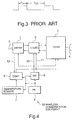
- Fig. 2 shows only a portion relating to the temperature control in the equipment which is directly relates to the present invention. That is, the inner temperature in the equipment is detected by temperature detecting means 21, and the detected result is transmitted to inner temperature control means 22. According to the detected result, the inner temperature control means 22 operates the fan, etc. in such a manner that the inner temperature in the equipment is lowered when the inner temperature in the equipment is high. When the inner temperature in the equipment is low, the inner temperature control means 22 operates the heater, etc. in such a manner that the inner temperature in the equipment is raised.
- power source supply portion control means 23 transmits a battery saving signal for a predetermined intermittent time to power source supply means 24.
- the power source supply means 24 is controlled in such a manner that the power source supplied to the inner portion of the equipment is limited by the battery saving signal from the power source supply portion control means 23.
- the consumed power in the equipment is controlled. For example, as shown in Fig. 3, according to the battery saving signal, a power source voltage is operated so that the power source of the power source supply means 24 may be turned on at an interval T on and it may be turned off at an interval T off .
- the communication equipment is not in a state of transmission or reception, such a battery saving operation is continued in order to reduce the consumed power. Furthermore, when the communication equipment is in a state of transmission or reception, the battery saving operation is stopped, so that a normal power source is supplied to the communication equipment.
- the inner temperature control means such as the fan, etc. must be additionally installed. Accordingly, the number of components of the equipment is increased, whereby there is such a problem that the equipment becomes larger.
- a wireless communication equipment for a remote station transmitting a signal between the remote station and a base station by using a TDMA communication system comprises temperature detecting means for detecting an inner temperature in the wireless communication equipment, first control means for changing a periodical time which intermittently operates a power source supplied to the wireless communication equipment according to the temperature detecting means when the wireless communication equipment is in an idle state, and second control means for changing a coding rate of the wireless communication equipment and a transmission burst time for the TDMA communication according to the temperature detecting means when the wireless communication equipment has a signal to be transmitted.
- a wireless communication equipment for a remote station transmitting a signal between the remote station and a base station by using a TDMA communication system comprises conversion means for converting an input/output signal into a predetermined form, coding/decoding means connected to the conversion means, for receiving a temperature control signal, for coding the received temperature control signal into a digital data having a predetermined coding rate, and for decoding an output signal from a predetermined digital data, transmission/reception means connected to the coding/decoding means, for receiving the temperature control signal, for transmitting a predetermined TDMA burst signal as a transmitted signal, and for outputting a demodulated data of a received wireless signal to the coding/decoding means, temperature detecting means for detecting the temperature in the wireless communication equipment, switch means for intermittently operating the power source supplied to the conversion means, the coding/decoding means and the transmission/reception means by receiving a battery saving signal, battery saving control means for receiving the output from the temperature detecting means,
- Fig. 1 shows a network construction of a conventional wireless communication system using a TDMA communication system comprising between a plurality of remote stations and a base station.
- Fig. 2 shows a construction of an inner temperature control of the wireless communication equipment of remote stations 200-1 to 200-n shown in Fig. 1.
- Fig. 3 shows a battery saving operation in Fig. 2.
- Fig. 4 is a block diagram of the wireless communication equipment of the remote station according to the present invention.
- Fig. 5 shows the battery saving operation according to a control of a temperature control portion 5 shown in Fig. 4 when a communication state is idle.
- Fig. 4 is a block diagram of a wireless communication equipment 5C of a remote station showing an embodiment according to the present invention.
- the wireless communication equipment 50 shown in Fig. 4 is accommodated in a box, similarly to a conventional technique.
- Fig. 4 shows a construction of the wireless communication equipment of the remote station when one-channel telephone line is transmitted/received between a master station (not shown) and a wireless line by a TDMA communication system.
- the wireless communication equipment 50 is characterized by that inner temperature control means such as a fan and the like which are conventionally used is not necessary.
- a numeral 9 denotes a two-wire line for transmitting a telephone line.
- a sound signal and the like are connected to a two-wire/four-wire converter 1 via the two-wire line 9.
- the two-wire/four-wire converter 1 has a function to convert a two-wire type signal into a four-wire type signal.
- An input/output signal from the two-wire/four-wire converter 1 is analog/digital converted by a CODEC 2.
- the CODEC 2 has a function to receive a temperature control signal 11 and to vary a coding rate.
- a maximum coding rate of the CODEC 2 is set to 64 kbps.
- Various band-compressed coding rates 32 kbps, 16 kbps and 4.8 kbps are controlled by the temperature control signal 11.
- the CODEC 2 may be an LSI which can select the coding rate in an inner portion in order to correspond to various coding rates. Furthermore, such a method that a plurality of CODECs having respective different coding rates are switched may be used.
- a transmission portion of a transmission/reception portion 3 receives a transmitted data digitized by the CODEC 2 and the transmitted data is modulated into a predetermined digital data
- the modulated data is transmitted as a TDMA transmission burst signal from an antenna 4.
- a reception portion receives the TDMA signal received from the antenna 4, and an obtained received data demodulated by a digital demodulator is outputted to the CODEC 2.
- a main power source 8 for the communication equipment supplies a power source supply to the two-wire/four-wire converter 1, the CODEC 2 and the transmission/reception portion 3, respectively via a power source switch 6 installed for turning on/off at a predetermined period by a power source line 10. Since the power source switch can carry out a switching at high speed, a power MOSFET switch is usually used.
- a temperature control portion 5 inputs a temperature sensor obtained by a temperature sensor 7 for sensing the temperature in the box which accommodates the communication equipment.
- the two-wire/four-wire converter 1 detects an on-hook signal or an off-hook signal of the telephone line detecting whether or not the signal to be transmitted to the two-wire line 9 exists. Therefore, the signal is inputted to the temperature control portion 5 as a transmission detecting signal 12.
- the temperature control portion 5 receives the transmission detecting signal 12. When the temperature control portion 5 judges that the communication equipment is not in a communication state, that is, it is in an idle state, a battery saving control for turning on/off the power source switch 6 is carried out.
- This battery saving operation is carried out in the following manner.
- the temperature control portion 5 which inputs the temperature data detected by the temperature sensor 7 compares the temperature to a predetermined set temperature. According to the compared result, the synchronization for turning on/off the power source switch 6 is changed, whereby a time period for the battery saving is controlled.
- the period for the battery saving is controlled in such a manner that a time for turning on the power source (T ON ) and a time for turning off the power source (T OFF ) are repeated at a predetermined period (T NORMAL ).
- T ON a time for turning on the power source
- T OFF a time for turning off the power source
- T NORMAL a predetermined period
- the time for turning off the power source is set to T OFF"' which is longer than T OFF , and the period is changed to a period T HIGH .
- a heat dissipation quantity is defined as Q ON .
- the heat dissipation quantity is defined as Q OFF . The following relationship is obtained : Q ON > Q OFF
- the average heat dissipation quantity and the temperature T o in the box can be approximate to each other by the following equation.
- T o is proportional to Q AVG .
- the more the average heat dissipation quantity in the box is increased the higher the temperature in the box is raised. While, the less the average heat dissipation quantity in the box is reduced, the lower the temperature in the box is fallen down.
- the average heat dissipation quantity in the box is determined by a ratio of T ON and T OFF . Accordingly, from a condition of the inequality (1), when T OFF is lengthened, the average heat dissipation quantity in the box is reduced. When T OFF is shortened, the average heat dissipation quantity in the box is increased.
- the temperature in the box is raised.
- the temperature in the box is fallen down.
- the battery saving period is changed, whereby the temperature in the box can be controlled so that it may be set to the set temperature without the fan and the like.
- the heat dissipation quantity of each communication equipment in the box is controlled, and a predetermined set temperature can be obtained.
- the communication equipment 50 inputs the transmission detecting signal 12 indicating the communication state to the temperature control portion 5.
- the temperature control portion 5 outputs the temperature control signal 11 for controlling the CODEC 2 and the transmission/reception portion 3.
- the temperature control portion 5 changes a transmission rate of the CODEC 2 in such a manner that a standard coding/decoding processing of 64 kbps is changed into, for example, a band-compressed coding/decoding processing of 32 kbps.
- the transmission rate is lowered.
- a data information as to a current transmission rate is inserted into a top portion of a burst data of the transmission data from the remote station.
- the inserted data information is transmitted to the base station.
- the base station changes a data rate of the transmission/reception portion thereof, whereby it is possible to communicate between the base station and the remote station.
- the temperature control signal 11 is inputted to the transmission/reception portion 3, and the temperature is controlled.
- the power consumed by a transmitted power amplifying portion in the transmission/reception pcrtion 3 is maximum. Furthermore, in the whole equipment, the maximum consumed power is generated in the transmitted power amplifying portion.
- the temperature control portion 5 compares the set temperature to the temperature in the box.
- the transmission rate of the CODEC is controlled in such a manner that the transmission rate may be changed, so that the temperature can be controlled.
- the battery saving operation which can vary the battery saving period all over the equipment is carried out, so that the temperature may be controlled.
- the battery saving operation is stopped relative to the communication-state channel. Simultaneously, the battery saving operation of the transmission/reception portion being a common portion is stopped.
- the coding rate of the CODEC and the transmission burst time of the transmission/reception portion are controlled, whereby the temperature may be controlled.
- the wireless communication equipment of the present invention when the equipment is not the communication state, the battery saving period is controlled.
- the coding rate of a sound CODEC and the transmitted data burst time of the transmitted power amplifying portion are controlled, so that there is such an effect that it is possible to provide the wireless communication equipment comprising only a simple construction which can control the temperature and have a high reliability.
Landscapes
- Engineering & Computer Science (AREA)
- Computer Networks & Wireless Communication (AREA)
- Signal Processing (AREA)
- Mobile Radio Communication Systems (AREA)
- Transceivers (AREA)
- Selective Calling Equipment (AREA)
Applications Claiming Priority (3)
| Application Number | Priority Date | Filing Date | Title |
|---|---|---|---|
| JP79981/96 | 1996-04-02 | ||
| JP7998196 | 1996-04-02 | ||
| JP7998196 | 1996-04-02 |
Publications (3)
| Publication Number | Publication Date |
|---|---|
| EP0800282A2 true EP0800282A2 (fr) | 1997-10-08 |
| EP0800282A3 EP0800282A3 (fr) | 2003-07-16 |
| EP0800282B1 EP0800282B1 (fr) | 2005-06-29 |
Family
ID=13705510
Family Applications (1)
| Application Number | Title | Priority Date | Filing Date |
|---|---|---|---|
| EP97400743A Expired - Lifetime EP0800282B1 (fr) | 1996-04-02 | 1997-04-01 | Equipement de communication sans fil pour une station à distance |
Country Status (3)
| Country | Link |
|---|---|
| US (1) | US5848062A (fr) |
| EP (1) | EP0800282B1 (fr) |
| AU (1) | AU714919B2 (fr) |
Cited By (8)
| Publication number | Priority date | Publication date | Assignee | Title |
|---|---|---|---|---|
| WO2000001094A1 (fr) * | 1998-06-30 | 2000-01-06 | Nokia Mobile Phones Limited | Transmission de donnees dans un systeme tdma |
| WO2000031990A2 (fr) * | 1998-11-20 | 2000-06-02 | Ericsson Inc. | Commande des transmissions thermiques d'un modem de donnees sans fil |
| WO2001020933A1 (fr) * | 1999-09-15 | 2001-03-22 | Telefonaktiebolaget Lm Ericsson | Emetteur radio a regulation thermique dans un systeme amrt |
| GB2355367A (en) * | 1999-10-13 | 2001-04-18 | Ericsson Telefon Ab L M | Adjusting allocation of transmission slots according operating conditions in a mobile telephone |
| EP1143627A1 (fr) * | 1999-11-05 | 2001-10-10 | Sony Corporation | Procede et dispositif d'emission de donnees |
| WO2002067442A2 (fr) * | 2001-02-16 | 2002-08-29 | Sierra Wireless, Inc. | Procede permettant d'eviter les temperatures de pointe dans les dispositifs de communication |
| WO2010129667A3 (fr) * | 2009-05-08 | 2010-12-29 | Qualcomm Incorporated | Puissance de transmission d'étranglement dans un dispositif wwan en fonction d'une entrée thermique |
| WO2012151161A1 (fr) * | 2011-05-03 | 2012-11-08 | Qualcomm Incorporated | Sélection de liaison radio en fonction de la température dans un dispositif sans fil multimode |
Families Citing this family (17)
| Publication number | Priority date | Publication date | Assignee | Title |
|---|---|---|---|---|
| JP3719482B2 (ja) * | 1998-07-29 | 2005-11-24 | 株式会社デンソー | 無線通信装置 |
| US7031258B1 (en) * | 2000-01-13 | 2006-04-18 | Mercury Computer Systems, Inc. | Digital data system with link level message flow control |
| US6433629B2 (en) * | 2000-01-24 | 2002-08-13 | Microstrain, Inc. | Micropower differential sensor measurement |
| US6560292B1 (en) * | 2000-04-07 | 2003-05-06 | Qualcomm Incorporated | Method for coding in a telecommunications system |
| US6785276B1 (en) * | 2000-07-25 | 2004-08-31 | Telefonaktiebolaget Lm Ericsson | System for tandem free operation in packet based communication |
| US20030040315A1 (en) * | 2001-08-20 | 2003-02-27 | Farideh Khaleghi | Reduced state transition delay and signaling overhead for mobile station state transitions |
| CN100505575C (zh) * | 2003-01-31 | 2009-06-24 | 诺基亚有限公司 | 多时隙上行链路的输出功率控制 |
| EP1530383B1 (fr) * | 2003-11-10 | 2006-06-14 | Research In Motion Limited | Méthode et système limitant les possibilités d'appel dans des appareils de communication mobiles |
| US7689256B2 (en) | 2003-11-10 | 2010-03-30 | Research In Motion Limited | Methods and apparatus for limiting communication capabilities in mobile communication devices |
| ATE461507T1 (de) * | 2004-10-18 | 2010-04-15 | Kidde Portable Equipment Inc | Gateway-einrichtung zur verbindung eines systems mit live-safety-einrichtungen |
| US20060106421A1 (en) * | 2004-11-16 | 2006-05-18 | Clifford Teoh | Expansible neck bridge |
| DE602007014392D1 (de) * | 2006-08-16 | 2011-06-16 | St Ericsson Sa | Betrieb einer integrierten schaltung |
| US7513683B2 (en) * | 2006-10-10 | 2009-04-07 | M & Fc Holding, Llc | Method, apparatus, and system for detecting hot socket deterioration in an electrical meter connection |
| US20080298287A1 (en) * | 2007-05-30 | 2008-12-04 | Motorola, Inc. | Priority scheme for communication system |
| US8150446B2 (en) * | 2009-06-17 | 2012-04-03 | Telefonaktiebolaget L M Ericsson (Publ) | Thermal energy control in a mobile transceiver |
| CN101931697A (zh) * | 2010-08-05 | 2010-12-29 | 华为终端有限公司 | 一种手持移动终端待机方法、微处理器及手机 |
| DE102011004752B4 (de) * | 2011-02-25 | 2021-10-28 | Apple Inc. | Signalverarbeitungsschaltung und Verfahren |
Citations (2)
| Publication number | Priority date | Publication date | Assignee | Title |
|---|---|---|---|---|
| US4939786A (en) * | 1987-03-09 | 1990-07-03 | Motorola, Inc. | Adaptive thermal protection for a power amplifier by remote sense |
| WO1996003811A1 (fr) * | 1994-07-21 | 1996-02-08 | Interdigital Technology Corporation | Procede et appareil pour diminuer la consommation de courant dans une unite d'abonne d'un systeme de telecommunication |
Family Cites Families (4)
| Publication number | Priority date | Publication date | Assignee | Title |
|---|---|---|---|---|
| JP2570596B2 (ja) * | 1993-09-27 | 1997-01-08 | 日本電気株式会社 | バッテリーセービングを行なう移動通信システム |
| FI941221A (fi) * | 1994-03-15 | 1995-09-16 | Nokia Mobile Phones Ltd | Menetelmä matkaviestinjärjestelmän radiopuhelimen tehonkulutuksen pienentämiseksi ja matkaviestin |
| JP2682444B2 (ja) * | 1994-05-31 | 1997-11-26 | 日本電気株式会社 | デジタル移動体通信交換システムと移動体通信交換機側データ通信アダプタ |
| US5561693A (en) * | 1994-08-01 | 1996-10-01 | Motorola, Inc. | Selective call receiver with battery saving features and method therefor |
-
1997
- 1997-04-01 AU AU16642/97A patent/AU714919B2/en not_active Ceased
- 1997-04-01 EP EP97400743A patent/EP0800282B1/fr not_active Expired - Lifetime
- 1997-04-02 US US08/825,733 patent/US5848062A/en not_active Expired - Fee Related
Patent Citations (2)
| Publication number | Priority date | Publication date | Assignee | Title |
|---|---|---|---|---|
| US4939786A (en) * | 1987-03-09 | 1990-07-03 | Motorola, Inc. | Adaptive thermal protection for a power amplifier by remote sense |
| WO1996003811A1 (fr) * | 1994-07-21 | 1996-02-08 | Interdigital Technology Corporation | Procede et appareil pour diminuer la consommation de courant dans une unite d'abonne d'un systeme de telecommunication |
Cited By (26)
| Publication number | Priority date | Publication date | Assignee | Title |
|---|---|---|---|---|
| GB2339113B (en) * | 1998-06-30 | 2003-05-21 | Nokia Mobile Phones Ltd | Data transmission in tdma system |
| WO2000001094A1 (fr) * | 1998-06-30 | 2000-01-06 | Nokia Mobile Phones Limited | Transmission de donnees dans un systeme tdma |
| EP2086125A3 (fr) * | 1998-06-30 | 2010-01-13 | Qualcomm Incorporated | Transmission de données dans un système TDMA |
| US7158489B1 (en) | 1998-06-30 | 2007-01-02 | Nokia Corporation | Data transmission in a TDMA system |
| EP1478107A3 (fr) * | 1998-06-30 | 2006-12-27 | Nokia Corporation | Transmission de données dans un système TDMA |
| EP1478107A2 (fr) * | 1998-06-30 | 2004-11-17 | Nokia Corporation | Transmission de données dans un système TDMA |
| US7860018B2 (en) | 1998-11-20 | 2010-12-28 | Ericsson Inc. | Thermal transmission control of wireless data modem |
| US6760311B1 (en) | 1998-11-20 | 2004-07-06 | Ericsson Inc. | Thermal transmission control of wireless data modem |
| WO2000031990A2 (fr) * | 1998-11-20 | 2000-06-02 | Ericsson Inc. | Commande des transmissions thermiques d'un modem de donnees sans fil |
| WO2000031990A3 (fr) * | 1998-11-20 | 2000-11-23 | Ericsson Inc | Commande des transmissions thermiques d'un modem de donnees sans fil |
| WO2001020933A1 (fr) * | 1999-09-15 | 2001-03-22 | Telefonaktiebolaget Lm Ericsson | Emetteur radio a regulation thermique dans un systeme amrt |
| GB2354402B (en) * | 1999-09-15 | 2004-02-11 | Ericsson Telefon Ab L M | Radio transmitter |
| US6934267B1 (en) | 1999-10-13 | 2005-08-23 | Telefonaktiebolaget L M Ericsson (Publ) | Time slot allocation control based on temperature in a radio transceiver |
| GB2355367A (en) * | 1999-10-13 | 2001-04-18 | Ericsson Telefon Ab L M | Adjusting allocation of transmission slots according operating conditions in a mobile telephone |
| EP1143627A1 (fr) * | 1999-11-05 | 2001-10-10 | Sony Corporation | Procede et dispositif d'emission de donnees |
| EP1143627A4 (fr) * | 1999-11-05 | 2003-08-06 | Sony Corp | Procede et dispositif d'emission de donnees |
| WO2002067442A3 (fr) * | 2001-02-16 | 2003-10-23 | Sierra Wireless Inc | Procede permettant d'eviter les temperatures de pointe dans les dispositifs de communication |
| US7200512B2 (en) | 2001-02-16 | 2007-04-03 | Sierra Wireless, Inc. | Method for avoiding peak temperatures in communication devices |
| WO2002067442A2 (fr) * | 2001-02-16 | 2002-08-29 | Sierra Wireless, Inc. | Procede permettant d'eviter les temperatures de pointe dans les dispositifs de communication |
| WO2010129667A3 (fr) * | 2009-05-08 | 2010-12-29 | Qualcomm Incorporated | Puissance de transmission d'étranglement dans un dispositif wwan en fonction d'une entrée thermique |
| US8229492B2 (en) | 2009-05-08 | 2012-07-24 | Qualcomm Incorporated | Throttling transmit power in a WWAN device based upon thermal input |
| WO2012151161A1 (fr) * | 2011-05-03 | 2012-11-08 | Qualcomm Incorporated | Sélection de liaison radio en fonction de la température dans un dispositif sans fil multimode |
| CN103621149A (zh) * | 2011-05-03 | 2014-03-05 | 高通股份有限公司 | 多模式无线装置中的温度驱动的空中链路选择 |
| US8675615B2 (en) | 2011-05-03 | 2014-03-18 | Qualcomm Incorporated | Temperature-driven airlink selection in a multi-mode wireless device |
| KR101536851B1 (ko) * | 2011-05-03 | 2015-07-14 | 퀄컴 인코포레이티드 | 멀티 모드 무선 디바이스에서의 온도 구동형 무선링크 선택 |
| CN103621149B (zh) * | 2011-05-03 | 2017-02-15 | 高通股份有限公司 | 多模式无线装置中的温度驱动的空中链路选择 |
Also Published As
| Publication number | Publication date |
|---|---|
| US5848062A (en) | 1998-12-08 |
| AU1664297A (en) | 1997-10-09 |
| EP0800282B1 (fr) | 2005-06-29 |
| EP0800282A3 (fr) | 2003-07-16 |
| AU714919B2 (en) | 2000-01-13 |
Similar Documents
| Publication | Publication Date | Title |
|---|---|---|
| EP0800282B1 (fr) | Equipement de communication sans fil pour une station à distance | |
| US5825761A (en) | Radio communication equipment with transmission rate regulating function | |
| WO2000031893A3 (fr) | Procede et appareil de commande de puissance bases sur la probabilite que l'instruction de commande de puissance est erronee | |
| EP2290835A3 (fr) | Appareil et procédé de réglage de puissance d'une pluralité de canaux dans un système de communications sans fil | |
| SE516557C2 (sv) | Dynamiskt kanalallokeringsförfarande | |
| AU8962098A (en) | Power saving method and apparatus for radio base station | |
| US20010014924A1 (en) | Clock adjustment method and apparatus | |
| EP0217412A2 (fr) | Dispositif de codage connecté sélectivement à une ligne de transmission | |
| US5682417A (en) | Power saving mobile data communication system using adaptors | |
| JP2976915B2 (ja) | 無線通信装置 | |
| US5930246A (en) | Bidirectional communication system | |
| AU663643B2 (en) | Digital communication apparatus including transmission error control | |
| EP0854657B1 (fr) | Procédé de surveillance de cellules voisines et station mobile | |
| KR20040055112A (ko) | 이동 통신 시스템 및 그의 과부하 방지 방법 | |
| US6144648A (en) | Communication system for making carrier synchronous | |
| US7684810B2 (en) | Trunking system control method | |
| US7522550B2 (en) | Automatic control apparatus and method for TD-SCDMA mobile terminal | |
| EP0936757A1 (fr) | Equipement et procede pour communication radio | |
| US7580160B2 (en) | Modem and facsimile apparatus capable of monitoring G3 communications via ISDN | |
| JPH1032586A (ja) | 無線lanシステム用通信方法及び通信装置 | |
| JP2991194B1 (ja) | マルチキャリアの受信方法および無線通信装置 | |
| JPH10200648A (ja) | モデムと電話線との間の接続装置 | |
| KR0145938B1 (ko) | 디지탈 교환기와 단말기간의 인터페이스 장치 | |
| KR100306284B1 (ko) | 무선가입자접속장치의사용자인터페이스장치 | |
| JP2830612B2 (ja) | 発着信数制御システム |
Legal Events
| Date | Code | Title | Description |
|---|---|---|---|
| PUAI | Public reference made under article 153(3) epc to a published international application that has entered the european phase |
Free format text: ORIGINAL CODE: 0009012 |
|
| AK | Designated contracting states |
Kind code of ref document: A2 Designated state(s): FR NL |
|
| PUAL | Search report despatched |
Free format text: ORIGINAL CODE: 0009013 |
|
| AK | Designated contracting states |
Designated state(s): FR NL |
|
| 17P | Request for examination filed |
Effective date: 20031217 |
|
| 17Q | First examination report despatched |
Effective date: 20040308 |
|
| GRAP | Despatch of communication of intention to grant a patent |
Free format text: ORIGINAL CODE: EPIDOSNIGR1 |
|
| GRAS | Grant fee paid |
Free format text: ORIGINAL CODE: EPIDOSNIGR3 |
|
| GRAA | (expected) grant |
Free format text: ORIGINAL CODE: 0009210 |
|
| AK | Designated contracting states |
Kind code of ref document: B1 Designated state(s): FR NL |
|
| PGFP | Annual fee paid to national office [announced via postgrant information from national office to epo] |
Ref country code: FR Payment date: 20060410 Year of fee payment: 10 |
|
| ET | Fr: translation filed | ||
| PGFP | Annual fee paid to national office [announced via postgrant information from national office to epo] |
Ref country code: NL Payment date: 20060417 Year of fee payment: 10 |
|
| PLBE | No opposition filed within time limit |
Free format text: ORIGINAL CODE: 0009261 |
|
| STAA | Information on the status of an ep patent application or granted ep patent |
Free format text: STATUS: NO OPPOSITION FILED WITHIN TIME LIMIT |
|
| 26N | No opposition filed |
Effective date: 20060330 |
|
| NLV4 | Nl: lapsed or anulled due to non-payment of the annual fee |
Effective date: 20071101 |
|
| PG25 | Lapsed in a contracting state [announced via postgrant information from national office to epo] |
Ref country code: NL Free format text: LAPSE BECAUSE OF NON-PAYMENT OF DUE FEES Effective date: 20071101 |
|
| PG25 | Lapsed in a contracting state [announced via postgrant information from national office to epo] |
Ref country code: FR Free format text: LAPSE BECAUSE OF NON-PAYMENT OF DUE FEES Effective date: 20070430 |