EP0800252B1 - Uninterrupted voltage supply having several constant-voltage charging devices - Google Patents
Uninterrupted voltage supply having several constant-voltage charging devices Download PDFInfo
- Publication number
- EP0800252B1 EP0800252B1 EP97106773A EP97106773A EP0800252B1 EP 0800252 B1 EP0800252 B1 EP 0800252B1 EP 97106773 A EP97106773 A EP 97106773A EP 97106773 A EP97106773 A EP 97106773A EP 0800252 B1 EP0800252 B1 EP 0800252B1
- Authority
- EP
- European Patent Office
- Prior art keywords
- voltage
- accumulators
- accumulator
- voltage supply
- nominal
- Prior art date
- Legal status (The legal status is an assumption and is not a legal conclusion. Google has not performed a legal analysis and makes no representation as to the accuracy of the status listed.)
- Expired - Lifetime
Links
Images


Classifications
-
- H—ELECTRICITY
- H02—GENERATION; CONVERSION OR DISTRIBUTION OF ELECTRIC POWER
- H02J—CIRCUIT ARRANGEMENTS OR SYSTEMS FOR SUPPLYING OR DISTRIBUTING ELECTRIC POWER; SYSTEMS FOR STORING ELECTRIC ENERGY
- H02J9/00—Circuit arrangements for emergency or stand-by power supply, e.g. for emergency lighting
- H02J9/04—Circuit arrangements for emergency or stand-by power supply, e.g. for emergency lighting in which the distribution system is disconnected from the normal source and connected to a standby source
- H02J9/06—Circuit arrangements for emergency or stand-by power supply, e.g. for emergency lighting in which the distribution system is disconnected from the normal source and connected to a standby source with automatic change-over, e.g. UPS systems
- H02J9/061—Circuit arrangements for emergency or stand-by power supply, e.g. for emergency lighting in which the distribution system is disconnected from the normal source and connected to a standby source with automatic change-over, e.g. UPS systems for DC powered loads
Definitions
- the present invention relates to an uninterruptible Power supply device according to the preamble of claim 1.
- the invention further relates to a method for operating a such uninterruptible power supply device.
- UPS uninterruptible power supply devices
- Core of any uninterruptible power supply device is an energy storage device, usually a storage device for electrical energy.
- Accumulators are usually used used, which is known to be a good compromise between Show cost, life and capacity. accumulators generally provide a DC voltage and are used with a DC voltage charged. For this reason, uninterrupted show Power supply devices, the accumulators as Use energy storage, generally a DC voltage supply on. However, it is understood that this DC power supply via suitable inverters with an AC power supply can be connected to e.g. the mains voltage buffering.
- the uninterruptible power supply devices To ensure that the batteries are constantly fully charged in order to be able to provide the full capacity if necessary the uninterruptible power supply devices one Charging device, which, fed from the regular voltage supply, the accumulator is always fully charged holds. For this it is crucial that the accumulator from the Charger is supplied with a voltage that something is higher than the nominal voltage of the accumulator. The amount of this so-called final charge voltage depends on the battery type. In a known accumulator with a nominal voltage of The final charge voltage is 24 volts 27.6 volts. This condition causes the known uninterruptible power supply devices are relatively expensive. Because the regular Power supply by the uninterruptible power supply device is to be buffered, only one Voltage ready, equal to the nominal voltage of the battery is. Therefore, this voltage in the charger must on the Final charge voltage above the nominal voltage increased become. Wear the DC converters necessary for this significantly to the high total cost of uninterrupted Power supply devices at.
- a direct current supply system for the uninterrupted supply of a consumer with constant direct voltage from a single or multi-phase alternating current network is known.
- the system has an unregulated main rectifier, a reserve battery and additional rectifier to keep the charge or trickle charge voltage for the battery and the voltage for the consumer constant.
- a first compensation device is connected, which is formed from an inverter with a rectifier connected downstream and is influenced by the battery voltage and, if necessary, provides positive or negative output voltage.
- the main rectifier and the consumer is a similar, but switched from the Disspannun g affect second balancing means.
- a power supply is from DE 38 10 397 C2 at least two batteries or accumulators connected in series for the current or voltage supply for an electrical Device known. For every battery or accumulator a diode is connected in parallel in the reverse direction. It is not described how these batteries or accumulators are charged become.
- From US-A-4,315,162 is an uninterruptible power supply device known for a microcomputer that manually switched between a "charging mode" and a “standby mode” can be.
- the device has two accumulators whose nominal voltage is lower than the voltage the DC voltage supply. They are in the charging mode two accumulators connected in parallel, the necessary Charging voltage via a voltage divider from the DC voltage supply is derived. In standby mode also takes place if the DC voltage supply is working, a trickle charge. If the DC voltage supply falls below one certain voltage threshold falls, the accumulators are switched on serially connecting bipolar transistor through.
- the uninterruptible Power supply device has two accumulators on, which are connected in series with each other in accumulator mode are connected to the DC voltage supply.
- the Accumulators are two from the DC voltage supply fed charging devices provided.
- One only in one Direction conductive device (diode) connects when the DC voltage supply is interrupted, the accumulators electrically with the connections of the DC voltage supply, to the power supply of connected electrical consumers in battery operation without interruption to maintain.
- an accumulator is supposed to be both a single one Accumulator as well as a serially connected block of Individual accumulators can be understood.
- each of the accumulators separate charging device provided.
- the device two accumulators, each with a nominal battery voltage half the nominal voltage of the DC voltage supply is.
- the nominal voltage of the DC voltage supply is in any case higher than the final charge voltage of each single accumulator.
- a Charger between a negative pole of a battery and the control device and a further charging device between a positive pole of the second accumulator and the Control device connected, with a positive pole of the an accumulator with a positive pole of the DC voltage supply and a negative pole of the second accumulator connected to a negative pole of the DC voltage supply is.
- control device between two of the accumulators are connected and if the Voltage of the DC voltage supply below the nominal voltage the accumulators electrically with the DC voltage supply combines.
- Decoupling is generally provided by such a control device between the charging operation of the accumulators and the accumulator operation the uninterruptible power supply device possible.
- the control device By arranging the control device between the Such a decoupling can have two accumulators in terms of circuitry can be realized particularly easily.
- the control device is a switch that switches the two Accumulators electrically connected to each other.
- the Control device between an accumulator and one assigned pole of the DC voltage supply connected and connects when the voltage of the DC voltage supply drops the batteries under the nominal voltage electrically with the DC voltage supply.
- the control device consists of two Switches that electrically connect the series batteries with the plus pole or the minus pole of the DC voltage supply connect.
- Block accumulators of advantage consisting of a series of serial interconnected individual accumulators exist. at such accumulator blocks, it is possible to Center tap for parallel charging of the individual accumulators provided.
- a switch can be inside the accumulator block however, as a rule, are not provided.
- the Final charge voltage of at least one of the accumulators is the same the nominal voltage of the DC voltage supply, the Charging device for one accumulator by a controllable one Switch is formed.
- This embodiment is particularly economical to produce, because for the one accumulator only one switch existing charging device can be provided.
- For the at least one other accumulator usually a very has much lower nominal battery voltage, a usual charging device provided, but due to the lower nominal battery voltage can be dimensioned smaller can.
- the charging device is controllable in such a way that the batteries are charged alternately become.
- the sum of the nominal voltages of the accumulators is greater than the nominal voltage of the DC voltage supply and if switching means are provided to in the accumulator mode a number of by means of the switching means selectable accumulators with the DC voltage supply to connect, the nominal voltage sum equal to the nominal voltage the DC voltage supply.
- the control device preferably has a comparator, the voltage of the DC voltage supply with a predetermined Compares threshold.
- the threshold value is preferably between 80 and 98%, in particular between 85 and 95% of the nominal voltage of the DC voltage supply.
- Such a threshold is for a variety of use cases particularly practical.
- control device has a Device for measuring the duration of the battery operation of the device.
- Such a time measuring device allows timely Turn off the uninterruptible power supply device before the battery voltage drops below a value at which the function of the connected consumers no longer can be guaranteed. Before reaching this state can also generate a warning signal based on the time measurement device be delivered.
- control device has a Device for optical, acoustic and / or electrical Display of the accumulator operation of the device.
- the display device makes it possible for the Inform operating personnel of this "malfunction". on the other hand can also display as a signal to a higher-level control unit be given automatically certain measures such as e.g. coordinated shutdown of the connected consumers initiates.
- the threshold of the comparator by one connected to the DC voltage circuit Zener diode formed.
- Zener diodes are due Its steep characteristic is particularly suitable for a predetermined one To form a threshold. Falling below this threshold triggers a change in current that leads to the generation of a Comparator output signal can be used.
- control device has a has electrically controllable switch with the comparator is connected and when the voltage of the DC voltage circuit drops below the threshold the two accumulators in series connects with each other.
- a control device is Particularly simple in terms of circuitry and therefore inexpensive to realize.
- a field effect transistor is preferably used as the switch used, the gate of which is connected to the comparator is. Because of the powerless controllability is a Field effect transistor especially for the purpose mentioned suitable.
- the Control device a device for current limitation and / or for voltage regulation.
- the current limitation can be connected to the between the two accumulators Realize control device particularly easily. Overall lets achieve this measure that from the uninterrupted Power supply device a limited current and a constant voltage can be taken.
- the control device preferably also has a temperature monitoring device which switches the device off when a predetermined temperature is exceeded. This measure avoids thermal overloading of the device, as a result of which the service life of the uninterruptible voltage supply device according to the invention is considerably extended. Particularly inexpensive temperature monitoring is achieved with a temperature-dependent resistor (eg NTC or PTC resistor).
- a temperature-dependent resistor eg NTC or PTC resistor
- UPS uninterruptible power supply device
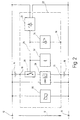
- the UPS 10 is connected to a DC voltage circuit or a DC voltage supply with a plus terminal 12 and a minus terminal 13 (usually ground) connected. Between Terminals 12, 13 are at a voltage U, for example one Nominal voltage of 12 volts or 24 volts.
- the UPS 10 has two identical batteries 14, 16 with each half the nominal voltage of the DC voltage circuit 12, 13.
- the battery 14 is connected to the plus terminal with its plus pole 12 of the DC voltage circuit 12, 13 connected.
- the accumulator 16 is with its minus pole to the minus terminal 13 of the DC voltage circuit 12, 13 connected.
- the accumulators 14, 16 are each provided with a charging device 18 or 20 assigned.
- the loading devices 18, 20 are each in parallel to terminals 12, 13 of the DC voltage circuit connected.
- the charging device 18 is at the negative pole 19 of the accumulator 14 connected.
- the charger 20 is connected to the positive pole 21 of the accumulator 16.
- a control device 22 is connected, which also with terminals 12, 13 of the DC circuit connected is.
- the DC circuit 12 13 is a regular, not DC voltage source shown to supply any electrical consumers available.
- the nominal voltage of this regular voltage source U 24 volts is.
- the UPS 10 is also for others Rated voltages suitable. It is also possible to connect to the terminals 12, 13 the DC output of an AC-DC converter to connect, so that the UPS 10 for uninterrupted Power supply of an AC voltage circuit is used. It is crucial that at terminals 12, 13 a voltage U is present, which is the behavior of the regular, buffered voltage source reflected.
- the nominal voltages are of the two accumulators 14, 16 each 12 volts.
- the charging devices 18, 20 can to this Purpose of having a fixed voltage regulator in an integrated form, the respective wiring generates a voltage of 13.7 volts.
- control device 22 The operation of the control device 22 is as follows explained with reference to FIG. 2.
- the control device 22 a comparator 24 connected to the terminals 12, 13 with a Zener diode on.
- the relatively high threshold of 22 volts and due to the short switching times of the components of the comparator 24 and the switch 26 becomes an uninterruptible power supply the consumers connected to terminals 12, 13 guaranteed.
- a device 28 for current limiting and voltage regulation is for current limitation between the pole 21 of the accumulator 16 and the switch 26 and for voltage regulation at the terminals 12, 13 connected.
- a temperature monitoring device 30 is between the Terminals 12, 13 connected and includes an NTC resistor. If a predetermined value is exceeded, by the choice of the NTC resistance The temperature monitoring device switches the predetermined temperature value 30 the uninterruptible power supply device 10 from.
- a timing device 32 is connected to the control line 25, the the duration of the accumulator operation of the measures the uninterruptible power supply device 10, that is, the period of time during which the switch 26 is turned on is. With the time measuring device 32, the uninterruptible Power supply device 10 switched off in good time before the one provided by the accumulators 14, 16 Voltage due to its discharge falling below a value with the functional reliability of those connected to terminals 12, 13 Consumer can no longer be guaranteed.
- the display device 34 serves the To display battery operation of the UPS 10, e.g. by means of the LED. Furthermore, the display device 34 can be used for electrical Signal are generated at an output terminal 36 that the Battery operation indicates. With the signal at the output connection 36 a higher-level control unit (not shown) are caused to coordinate the shutdown of the connected Initiate consumers. For this purpose, the duration of the accumulator operation determined by the time measuring device 32 be transmitted to the control unit.
- FIGS. 3 to 6 show alternative embodiments of Uninterruptible power supply devices according to the invention shown.
- the UPS 40 shown in FIG. 3 has two accumulators 42, 44 on, which are connected to one another in series via a switch 46 are.
- the arrangement of the two batteries 42, 44 and the Switch 46 is connected in parallel to the DC voltage supply 12, 13 connected.
- a switch 50 is between the negative pole of the battery 42 and the negative pole 13 of the DC voltage supply 12, 13 connected.
- the accumulator 42 has a final charge voltage, which is equal to the nominal voltage U of the DC voltage supply 12, 13 is.
- the switch 50 therefore forms a charging device for the accumulator 42.
- a common one is for the accumulator 44
- Charging device 48 is provided, for example the charging device 20 of Fig. 1 corresponds, but for a very large amount lower final charge voltage is designed.
- a diode 52 is provided to the in the accumulator operation Separate load section from the supply section 12, 13. Such a diode 52 can also be used in all other embodiments the invention are used.
- the Nominal voltage U of the DC voltage supply 12, 13 24 volts is.
- the nominal voltage of the accumulator 42 are 20 volts and the final charge voltage is 24 volts.
- the nominal voltage of the accumulator 44 is 4 volts, so that the charging device 48 has an end-of-charge voltage of e.g. Provides 4.8 volts.
- the accumulators 42, 44 can also consist of a number of Single cells must be constructed. For example, a single cell with a nominal voltage of 2 volts and a final charge voltage from 2.35 to 2.4 volts can be provided.
- the accumulator 42 in this case consists of ten such individual cells.
- the In this case, the accumulator 44 consists of two such individual cells.
- the UPS 60 shown in FIG. 4 has three accumulators 62, 64, 66 on. There is a between the accumulators 64 and 62 Switch 68 connected. The accumulators 64, 66 are serial connected with each other. The negative pole of the accumulator 66 is with the negative pole 13 of the DC voltage supply 12, 13 connected. The positive pole of the accumulator 62 is with the positive pole 12 of the DC voltage supply 12, 13 connected. Two charging devices 70, 72 are also provided, the mode of operation of the charging devices 18, 20 of FIG. 1 equivalent. Charger 70 is between the switch 68 and the accumulator 62 connected. The charger 72 is connected between the switch 68 and the accumulator 64.
- An AC-DC converter 74 is also provided, the between an AC voltage U ⁇ and the poles 12, 13 connected. This is intended to clarify that the Uninterruptible power supply devices according to the invention also suitable for buffering alternating voltages are, provided a suitable AC-DC converter is provided.
- Power supply device 80 is in FIG. 5 shown.
- the UPS 80 has three accumulators 82, 84, 86. Between a switch 88 is connected to the accumulators 82, 84.
- a switch 90 is connected between the accumulators 84, 86. There are also three charging devices 92, 94, 96 provided. Charger 92 is between the switch 88 and the accumulator 82 connected. The charger 94 is connected between the switch 88 and the accumulator 84. Charger 96 is between the switch 90 and the accumulator 86 connected.
- a switch 98 is provided, which between the negative pole of the accumulator 84 and the negative pole 13 the DC voltage supply 12, 13 is connected.
- the switches are during the regular power supply 88, 90 open.
- the accumulators 82, 86 are by the Chargers 92, 96 constantly charged.
- the accumulator 84 is loaded as soon as switch 98 is closed.
- the switch 98 can be opened to charge the battery 84 interrupt and thereby the resulting To reduce heat loss.
- a switch 99 is also shown, which between the positive pole of the accumulator 84 and the positive pole 12 of the DC voltage supply 12, 13 is connected.
- This Switch is optionally provided in the event that the sum the nominal voltages of the accumulators 82, 84, 86 is greater than the nominal voltage U of the DC voltage supply 12, 13.
- the nominal voltage U of the DC voltage supply 12, 13 U 24 volts and the nominal voltage the accumulators 82, 84, 86 each have 12 volts.
- the switches 88, 98 closed or the switches 90, 99 so that only two of the accumulators 82, 84, 86 used for accumulator operation become.
- This circuit variant is based on the Principle of redundancy. If one of the accumulators 82, 86 the uninterruptible power supply can fail via the accumulator 84 and the non-failed one Accumulator of the accumulators 82, 86 are maintained.
- the embodiment shown in Fig. 6 of an inventive UPS 100 includes two accumulators 102, 104 and two switches 106, 108.
- Switch 106 is between the positive pole of the Accumulator 102 and the positive pole 12 of the DC voltage supply 12, 13 connected.
- the switch 108 is between the negative pole of the accumulator 104 and the negative pole 13 of the DC voltage supply 12, 13 connected.
- the UPS 100 thus largely corresponds to the UPS 10 from FIG. 1. Instead of one switch 26, there are two switches 106, 108 provided. This embodiment is particular then advantageous if the accumulators 102, 104 in the form of a Accumulator block are present, so that between them a Connection lug for connecting the charging devices 110, 112 can be provided, but not a switch or only under major construction effort is connected.
- the UPS 100 can are therefore extremely compact.
Abstract
Description
Die vorliegende Erfindung betrifft eine unterbrechungsfreie Spannungsversorgungsvorrichtung nach Oberbegriff des Anspruchs 1.The present invention relates to an uninterruptible Power supply device according to the preamble of claim 1.
Die Erfindung betrifft ferner ein Verfahren zum Betreiben einer solchen unterbrechungsfreien Spannungsversorgungsvorrichtung.The invention further relates to a method for operating a such uninterruptible power supply device.
Eine derartige unterbrechungsfreie Spannungsversorgungsvorrichtung bzw. ein derartiges Verfahren sind bekannt aus der US-A-4,297,629. Such an uninterruptible power supply device or such a method are known from the US-A-4,297,629.
Solche unterbrechungsfreien Spannungsversorgungsvorrichtungen sind allgemein bekannt und werden häufig mit der Abkürzung USV bezeichnet.Such uninterruptible power supply devices are well known and are often abbreviated to UPS designated.
Das Anwendungsgebiet der unterbrechungsfreien Spannungsversorgungsvorrichtungen ist außerordentlich groß. Überall dort, wo der Ausfall einer regulären Spannungsquelle aus den verschiedensten Gründen nicht hingenommen werden kann, dient eine unterbrechungsfreie Spannungsversorgungsvorrichtung zur Sicherstellung der Spannungsversorgung für einen begrenzten Zeitraum, wenn die reguläre Spannungsquelle ausfällt.The field of application of uninterruptible power supply devices is extremely large. Everywhere over there, where the failure of a regular voltage source from the most varied One cannot serve reasons uninterruptible power supply device to ensure the power supply for a limited period of time, if the regular voltage source fails.
"Kern" einer jeden unterbrechungsfreien Spannungsversorgungsvorrichtung ist ein Energiespeicher, üblicherweise ein Speicher für elektrische Energie. Gewöhnlich werden Akkumulatoren verwendet, die bekannterweise einen guten Kompromiß zwischen Kosten, Lebensdauer und Kapazität darstellen. Akkumulatoren stellen generell eine Gleichspannung bereit und werden mit einer Gleichspannung geladen. Aus diesem Grund weisen unterbrechungsfreie Spannungsversorgungsvorrichtungen, die Akkumulatoren als Energiespeicher verwenden, generell eine Gleichspannungsversorgung auf. Es versteht sich jedoch, daß diese Gleichspannungsversorgung über geeignete Umrichter mit einer Wechselstromversorgung verbunden sein kann, um z.B. die Netzspannung abzupuffern."Core" of any uninterruptible power supply device is an energy storage device, usually a storage device for electrical energy. Accumulators are usually used used, which is known to be a good compromise between Show cost, life and capacity. accumulators generally provide a DC voltage and are used with a DC voltage charged. For this reason, uninterrupted show Power supply devices, the accumulators as Use energy storage, generally a DC voltage supply on. However, it is understood that this DC power supply via suitable inverters with an AC power supply can be connected to e.g. the mains voltage buffering.
Um sicherzustellen, daß die Akkumulatoren ständig voll aufgeladen sind, um ggf. die volle Kapazität bereitstellen zu können, weisen die unterbrechungsfreien Spannungsversorgungsvorrichtungen eine Ladeeinrichtung auf, die, gespeist aus der regulären Spannungsversorgung, den Akkumulator ständig im vollgeladenen Zustand hält. Hierzu ist es entscheidend, daß der Akkumulator von der Ladeeinrichtung mit einer Spannung versorgt wird, die etwas höher ist als die Nennspannung des Akkumulators. Die Höhe dieser sogenannten Ladeschlußspannung hängt vom Akkumulatortyp ab. Bei einem bekannten Akkumulator mit einer Nennspannung von 24 Volt beträgt die Ladeschlußspannung 27,6 Volt. Dieser Umstand verursacht, daß die bekannten unterbrechungsfreien Spannungsversorgungsvorrichtungen relativ teuer sind. Denn die reguläre Spannungsversorgung, die von der unterbrechungsfreien Spannungsversorgungsvorrichtung abzupuffern ist, stellt lediglich eine Spannung bereit, die gleich der Nennspannung des Akkumulators ist. Daher muß diese Spannung in der Ladeeinrichtung auf die über der Nennspannung liegende Ladeschlußspannung hochgesetzt werden. Die hierzu notwendigen Gleichstromumsetzer tragen wesentlich zu den hohen Gesamtkosten der unterbrechungsfreien Spannungsversorgungsvorrichtungen bei.To ensure that the batteries are constantly fully charged in order to be able to provide the full capacity if necessary the uninterruptible power supply devices one Charging device, which, fed from the regular voltage supply, the accumulator is always fully charged holds. For this it is crucial that the accumulator from the Charger is supplied with a voltage that something is higher than the nominal voltage of the accumulator. The amount of this so-called final charge voltage depends on the battery type. In a known accumulator with a nominal voltage of The final charge voltage is 24 volts 27.6 volts. This condition causes the known uninterruptible power supply devices are relatively expensive. Because the regular Power supply by the uninterruptible power supply device is to be buffered, only one Voltage ready, equal to the nominal voltage of the battery is. Therefore, this voltage in the charger must on the Final charge voltage above the nominal voltage increased become. Wear the DC converters necessary for this significantly to the high total cost of uninterrupted Power supply devices at.
Aus der DE-AS 20 61 120 ist ein Gleichstromversorgungssystem zur unterbrechungsfreien Speisung eines Verbrauchers mit konstanter Gleichspannung aus einem ein- oder mehrphasigen Wechselstromnetz bekannt. Das System weist einen ungeregelten Hauptgleichrichter, eine Reservebatterie und Zusatzgleichrichter zur Konstanthaltung der Lade- bzw. Ladeerhaltungsspannung für die Batterie und der Spannung für den Verbraucher auf. Zwischen den Hauptgleichrichter und die Batterie ist eine aus einem Wechselrichter mit nachgeschaltetem Gleichrichter gebildete, von der Batteriespannung beeinflußte und bedarfsweise positive oder negative Ausgangsspannung liefernde, erste Ausgleichseinrichtung geschaltet. Zwischen den Hauptgleichrichter und den Verbraucher ist eine gleichartige, jedoch von der Verbraucherspannung beeinflußte zweite Ausgleichseinrichtung geschaltet. From DE-AS 20 61 120 a direct current supply system for the uninterrupted supply of a consumer with constant direct voltage from a single or multi-phase alternating current network is known. The system has an unregulated main rectifier, a reserve battery and additional rectifier to keep the charge or trickle charge voltage for the battery and the voltage for the consumer constant. Between the main rectifier and the battery, a first compensation device is connected, which is formed from an inverter with a rectifier connected downstream and is influenced by the battery voltage and, if necessary, provides positive or negative output voltage. Between the main rectifier and the consumer is a similar, but switched from the Verbraucherspannun g affect second balancing means.
Weiterhin ist aus der DE 38 10 397 C2 eine Stromversorgung mit mindestens zwei in Reihe geschalteten Batterien bzw. Akkumulatoren zur Strom- bzw. Spannungsversorgung für ein elektrisches Gerät bekannt. Zu jeder Batterie bzw. zu jedem Akkumulator ist eine Diode in Sperrichtung parallel geschaltet. Es ist nicht beschrieben, wie diese Batterien bzw. Akkumulatoren geladen werden. Furthermore, a power supply is from DE 38 10 397 C2 at least two batteries or accumulators connected in series for the current or voltage supply for an electrical Device known. For every battery or accumulator a diode is connected in parallel in the reverse direction. It is not described how these batteries or accumulators are charged become.
Aus der US-A-4,315,162 ist eine unterbrechungsfreie Spannungsversorgungsvorrichtung für einen Mikrocomputer bekannt, die manuell zwischen einem "Lademodus" und einem "Standby-Modus" umgeschaltet werden kann. Die Vorrichtung weist zwei Akkumulatoren auf, deren Nennspannung jeweils kleiner ist als die Spannung der Gleichspannungsversorgung. In dem Lademodus sind die zwei Akkumulatoren parallel geschaltet, wobei die notwendige Ladespannung über einen Spannungsteiler aus der Gleichspannungsversorgung abgeleitet wird. Im Standby-Modus erfolgt ebenfalls bei Funktionieren der Gleichspannungsversorgung eine Erhaltungsladung. Falls die Gleichspannungsversorgung unter eine bestimmte Spannungsschwelle fällt, schaltet ein die Akkumulatoren seriell verbindender Bipolar-Transistor durch.From US-A-4,315,162 is an uninterruptible power supply device known for a microcomputer that manually switched between a "charging mode" and a "standby mode" can be. The device has two accumulators whose nominal voltage is lower than the voltage the DC voltage supply. They are in the charging mode two accumulators connected in parallel, the necessary Charging voltage via a voltage divider from the DC voltage supply is derived. In standby mode also takes place if the DC voltage supply is working, a trickle charge. If the DC voltage supply falls below one certain voltage threshold falls, the accumulators are switched on serially connecting bipolar transistor through.
Aus der eingangs genannten US-A-4,297,629 ist eine unterbrechungsfreie Spannungsversorgungsvorrichtung bekannt, die zum Anschluß an eine, eine Versorgungsspannung bereitstellende Gleichspannungsversorgung ausgelegt ist. Die unterbrechungsfreie Spannungsversorgungsvorrichtung weist zwei Akkumulatoren auf, die im Akkumulatorbetrieb miteinander in Serie geschaltet mit der Gleichspannungsversorgung verbunden sind. Für die Akkumulatoren sind zwei aus der Gleichspannungsversorgung gespeiste Ladeeinrichtungen vorgesehen. Eine nur in eine Richtung leitfähige Einrichtung (Diode) verbindet dann, wenn die Gleichspannungsversorgung unterbrochen ist, die Akkumulatoren elektrisch mit den Anschlüssen der Gleichspannungsversorgung, um die Spannungsversorgung von daran angeschlossenen elektrischen Verbrauchern im Akkumulatorbetrieb unterbrechungsfrei aufrecht zu erhalten. From the above-mentioned US-A-4,297,629 is an uninterruptible Voltage supply device known for Connection to one that provides a supply voltage DC voltage supply is designed. The uninterruptible Power supply device has two accumulators on, which are connected in series with each other in accumulator mode are connected to the DC voltage supply. For the Accumulators are two from the DC voltage supply fed charging devices provided. One only in one Direction conductive device (diode) connects when the DC voltage supply is interrupted, the accumulators electrically with the connections of the DC voltage supply, to the power supply of connected electrical consumers in battery operation without interruption to maintain.
Vor diesem Hintergrund ist es die Aufgabe der vorliegenden Erfindung, eine verbesserte unterbrechungsfreie Spannungsversorgung sowie ein Verfahren zum Betrieb einer solchen anzugeben.Against this background, it is the object of the present invention an improved uninterruptible power supply and to specify a method for operating such.
Diese Aufgabe wird bei der eingangs genannten unterbrechungsfreien Spannungsversorgungsvorrichtung durch die Merkmale des Anspruchs 1 gelöst.This task is uninterrupted in the aforementioned Power supply device solved by the features of claim 1.
Diese Aufgabe
wird ferner durch ein Verfahren zum Betreiben einer
solchen unterbrechungsfreien Spannungsversorgungsvorrichtung
mit den Schritten des
Anpruchs 13 gelöst.
der Gesamtnennspannung. Aus diesem Grund läßt sich die Ladeschlußspannung
außerordentlich einfach aus der entsprechenden
Nennspannung der regulären Spannungsversorgungseinrichtung
herleiten. Bekanntlich läßt sich aus einer vorgegebenen Spannung
jede beliebige niedrigere Spannung durch einfachste schaltungstechnische
Mittel bereitstellen, z.B. durch einen Spannungsteiler.
Daher läßt sich die erfindungsgemäße unterbrechungsfreie
Spannungsversorgungsvorrichtung sehr viel kostengünstiger
herstellen als bekannte derartige Vorrichtungen, bei denen die
Ladeschlußspannung auf schaltungstechnisch aufwendige Weise
erzeugt werden muß.This task
is further enhanced by a method of operating a
such uninterruptible power supply device
with the steps of
Unter einem Akkkumulator soll vorliegend sowohl ein einzelner Akkumulator als auch ein seriell verschalteter Block von Einzelakkumulatoren verstanden werden.In the present case, an accumulator is supposed to be both a single one Accumulator as well as a serially connected block of Individual accumulators can be understood.
Die Aufgabe wird somit vollkommen gelöst.The task is thus solved completely.
Erfindungsgemäβ ist für jeden der Akkumulatoren eine separate Ladeeinrichtung vorgesehen.According to the invention there is one for each of the accumulators separate charging device provided.
Durch diese Maßnahme können die Ladevorgänge der einzelnen Akkumulatoren unabhängig voneinander ausgeführt werden. Da es sich aus fertigungstechnischen Gründen nicht vermeiden läßt, daß auch Akkumulatoren desselben Typs unterschiedliche Innenwiderstände aufweisen, werden durch diese Maßnahme Überlastungen einzelner Akkumulatoren vermieden. Jeder Akkumulator kann voll aufgeladen werden.Through this measure, the charging processes of the individual Accumulators can be run independently of each other. Because it cannot be avoided for manufacturing reasons, that also accumulators of the same type have different internal resistances this measure will result in overloads individual accumulators avoided. Every accumulator can be full to be charged.
Gemäß einer bevorzugten Ausführungsform weist die Vorrichtung zwei Akkumulatoren auf, deren Akkumulatornennspannung jeweils die halbe Nennspannung der Gleichspannungsversorgung beträgt.According to a preferred embodiment, the device two accumulators, each with a nominal battery voltage half the nominal voltage of the DC voltage supply is.
Durch die Verwendung von nur zwei Akkumulatoren können die Kosten minimiert werden. Es können Akkumulatoren desselben Typs eingesetzt werden. Die Nennspannung der Gleichspannungsversorgung ist in jedem Fall höher als die Ladeschlußspannung jedes einzelnen Akkumulators.By using only two accumulators the cost can be reduced be minimized. Accumulators of the same type can be used be used. The nominal voltage of the DC voltage supply is in any case higher than the final charge voltage of each single accumulator.
Gemäß einer weiteren bevorzugten Ausführungsform ist eine Ladeeinrichtung zwischen einem negativen Pol des einen Akkumulators und der Steuereinrichtung und eine weitere Ladeeinrichtung zwischen einem positiven Pol des zweiten Akkumulators und der Steuereinrichtung angeschlossen, wobei ein positiver Pol des einen Akkumulators mit einem positiven Pol der Gleichspannungsversorgung und ein negativer Pol des zweiten Akkumulators mit einem negativen Pol der Gleichspannungsversorgung verbunden ist.According to a further preferred embodiment, a Charger between a negative pole of a battery and the control device and a further charging device between a positive pole of the second accumulator and the Control device connected, with a positive pole of the an accumulator with a positive pole of the DC voltage supply and a negative pole of the second accumulator connected to a negative pole of the DC voltage supply is.
Diese Realisierung des Anschlusses der Akkumulatoren an die Gleichspannungsversorgung und des Anschlusses der Ladeeinrichtungen an die Akkumulatoren ist schaltungstechnisch besonders einfach und damit kostengünstig.This realization of the connection of the accumulators to the DC voltage supply and the connection of the charging devices the accumulators are special in terms of circuitry simple and therefore inexpensive.
Es ist weiterhin bevorzugt, wenn die Steuereinrichtung zwischen zwei der Akkumulatoren angeschlossen ist und bei Abfall der Spannung der Gleichspannungsversorgung unter die Nennspannung die Akkumulatoren elektrisch mit der Gleichspannungsversorgung verbindet.It is further preferred if the control device between two of the accumulators are connected and if the Voltage of the DC voltage supply below the nominal voltage the accumulators electrically with the DC voltage supply combines.
Durch eine solche Steuereinrichtung ist generell eine Entkopplung zwischen dem Ladebetrieb der Akkumulatoren und dem Akkumulatorbetrieb der unterbrechungsfreien Spannungsversorgungsvorrichtung möglich. Durch Anordnung der Steuereinrichtung zwischen den zwei Akkumulatoren kann eine solche Entkopplung schaltungstechnisch besonders einfach realisiert werden. Im einfachsten Fall ist die Steuereinrichtung ein Schalter, der die zwei Akkumulatoren elektrisch miteinander verbindet.Decoupling is generally provided by such a control device between the charging operation of the accumulators and the accumulator operation the uninterruptible power supply device possible. By arranging the control device between the Such a decoupling can have two accumulators in terms of circuitry can be realized particularly easily. In the simplest Case, the control device is a switch that switches the two Accumulators electrically connected to each other.
Gemäß einem weiteren bevorzugten Ausführungsbeispiel ist die Steuereinrichtung jeweils zwischen einem Akkumulator und einem zugeordneten Pol der Gleichspannungsversorgung angeschlossen und verbindet bei Abfall der Spannung der Gleichspannungsversorgung unter die Nennspannung die Akkumulatoren elektrisch mit der Gleichspannungsversorgung.According to a further preferred exemplary embodiment, the Control device between an accumulator and one assigned pole of the DC voltage supply connected and connects when the voltage of the DC voltage supply drops the batteries under the nominal voltage electrically with the DC voltage supply.
Auch in diesem Fall ist eine Entkopplung zwischen dem Ladebetrieb der Akkumulatoren und dem Akkumulatorbetrieb der unterbrechungsfreien Spannungsversorgungsvorrichtung möglich. In diesem Fall besteht die Steuereinrichtung im einfachsten Fall aus zwei Schaltern, die die in Serie geschalteten Akkumulatoren elektrisch mit dem Plus-Pol bzw. dem Minus-Pol der Gleichspannungsversorgung verbinden. Diese Anordnung ist insbesondere bei Verwendung von Blockakkumulatoren von Vorteil, die aus einer Reihe von seriell miteinander verbundenen Einzelakkumulatoren bestehen. Bei derartigen Akkumulatorblöcken ist es zwar möglich, einen Mittenabgriff zum parallelen Laden der Einzelakkumulatoren vorzusehen. Ein Schalter kann innerhalb des Akkumulatorblockes jedoch in aller Regel nicht vorgesehen werden. In this case, there is a decoupling between the charging mode the accumulators and the accumulator operation of the uninterruptible Power supply device possible. In this case in the simplest case, the control device consists of two Switches that electrically connect the series batteries with the plus pole or the minus pole of the DC voltage supply connect. This arrangement is particularly useful when using Block accumulators of advantage, consisting of a series of serial interconnected individual accumulators exist. at such accumulator blocks, it is possible to Center tap for parallel charging of the individual accumulators provided. A switch can be inside the accumulator block however, as a rule, are not provided.
Gemäß einem weiteren bevorzugten Ausführungsbeispiel ist die Ladeschlußspannung von wenigstens einem der Akkumulatoren gleich der Nennspannung der Gleichspannungsversorgung, wobei die Ladeeinrichtung für den einen Akkumulator durch einen steuerbaren Schalter gebildet ist.According to a further preferred exemplary embodiment, the Final charge voltage of at least one of the accumulators is the same the nominal voltage of the DC voltage supply, the Charging device for one accumulator by a controllable one Switch is formed.
Diese Ausführungsform ist besonders kostengünstig zu produzieren, da für den einen Akkumulator eine lediglich aus einem Schalter bestehende Ladeeinrichtung vorgesehen werden kann. Für den wenigstens einen weiteren Akkumulator, der gewöhnlich eine sehr viel geringere Akkumulatornennspannung aufweist, wird eine übliche Ladeeinrichtung vorgesehen, die jedoch aufgrund der geringeren Akkumulatornennspannung kleiner dimensioniert sein kann.This embodiment is particularly economical to produce, because for the one accumulator only one switch existing charging device can be provided. For the at least one other accumulator, usually a very has much lower nominal battery voltage, a usual charging device provided, but due to the lower nominal battery voltage can be dimensioned smaller can.
Es ist weiterhin von besonderem Vorzug, wenn die Ladeeinrichtung derart steuerbar ist, daß die Akkumulatoren abwechselnd geladen werden.It is also particularly preferable if the charging device is controllable in such a way that the batteries are charged alternately become.
Diese Maßnahme basiert auf dem Gedanken, daß es zur Bereitstellung der erforderlichen Akkumulatorkapazität nicht erforderlich ist, sämtliche Akkumulatoren ständig mit der Ladeschlußspannung zu versorgen. Durch den zeitlichen Versatz des Aufladens von Akkumulatoren können die Verluste daher insgesamt minimiert werden, was insbesondere zu einer geringeren Verlustwärme führt, die bei unterbrechungsfreien Spannungsversorgungsvorrichtungen generell ein Problem darstellt.This measure is based on the idea that it is for deployment the required battery capacity is not required is, all accumulators with the final charge voltage to supply. Due to the delay in charging accumulators can therefore minimize the overall losses which in particular leads to less heat loss, that with uninterruptible power supply devices generally represents a problem.
Weiterhin ist es bevorzugt, wenn die Summe der Nennspannungen der Akkumulatoren größer ist als die Nennspannung der Gleichspannungsversorgung und wenn Schaltmittel vorgesehen sind, um im Akkumulatorbetrieb eine Anzahl von mittels der Schaltmittel auswählbaren Akkumulatoren mit der Gleichspannungsversorgung zu verbinden, deren Nennspannungssumme gleich der Nennspannung der Gleichspannungsversorgung ist.Furthermore, it is preferred if the sum of the nominal voltages of the accumulators is greater than the nominal voltage of the DC voltage supply and if switching means are provided to in the accumulator mode a number of by means of the switching means selectable accumulators with the DC voltage supply to connect, the nominal voltage sum equal to the nominal voltage the DC voltage supply.
Hierdurch wird eine hohe Redundanz erreicht, so daß beispielsweise bei Ausfall eines Akkumulators die unterbrechungsfreie Spannungsversorgung dennoch gewährleistet ist. Zum anderen kann hierdurch die Belastung der Einzelakkumulatoren verringert werden, so daß die unterbrechungsfreie Spannungsversorgungsvorrichtung insgesamt eine längere Lebensdauer aufweist.As a result, a high level of redundancy is achieved, so that, for example in the event of a battery failure, the uninterruptible Power supply is still guaranteed. On the other hand this reduces the load on the individual accumulators be so that the uninterruptible power supply device overall has a longer lifespan.
Vorzugsweise weist die Steuereinrichtung einen Komparator auf, der die Spannung der Gleichspannungsversorgung mit einem vorbestimmten Schwellenwert vergleicht.The control device preferably has a comparator, the voltage of the DC voltage supply with a predetermined Compares threshold.
Durch diese Maßnahme läßt sich besonders einfach erkennen, ob ein unzulässiger Spannungsabfall der Gleichspannungsversorgung vorliegt. Gleichzeitig kann durch Auswahl eines geeigneten Schwellenwertes vermieden werden, daß die Steuereinrichtung den Akkumulatorbetrieb bei Spannungsabfällen innerhalb eines zulässigen Toleranzbereiches auslöst.This measure makes it particularly easy to see whether an impermissible voltage drop in the DC voltage supply is present. At the same time, by choosing a suitable one Threshold values are avoided that the control device the accumulator operation in case of voltage drops within one permissible tolerance range.
Vorzugsweise beträgt der Schwellenwert zwischen 80 und 98 %, insbesondere zwischen 85 und 95 % der Nennspannung der Gleichspannungsversorgung.The threshold value is preferably between 80 and 98%, in particular between 85 and 95% of the nominal voltage of the DC voltage supply.
Ein solcher Schwellenwert ist für eine Vielzahl von Anwendungsfällen besonders praktikabel.Such a threshold is for a variety of use cases particularly practical.
Es ist weiterhin bevorzugt, wenn die Steuereinrichtung eine Einrichtung zur Messung der Zeitdauer des Akkumulatorbetriebs der Vorrichtung aufweist. It is further preferred if the control device has a Device for measuring the duration of the battery operation of the device.
Eine solche Zeitmeßeinrichtung gestattet das rechtzeitige Abschalten der unterbrechungsfreien Spannungsversorgungsvorrichtung vor Abfall der Akkumulatorspannung unter einen Wert, bei dem die Funktion der angeschlossenen Verbraucher nicht mehr gewährleistet werden kann. Vor dem Erreichen dieses Zustandes kann auf der Grundlage der Zeitmeßeinrichtung auch ein Warnsignal abgegeben werden.Such a time measuring device allows timely Turn off the uninterruptible power supply device before the battery voltage drops below a value at which the function of the connected consumers no longer can be guaranteed. Before reaching this state can also generate a warning signal based on the time measurement device be delivered.
Schließlich ist es bevorzugt, wenn die Steuereinrichtung eine Einrichtung zur optischen, akustischen und/oder elektrischen Anzeige des Akkumulatorbetriebs der Vorrichtung aufweist.Finally, it is preferred if the control device has a Device for optical, acoustic and / or electrical Display of the accumulator operation of the device.
Da die Spannungsversorgung durch die erfindungsgemäße unterbrechungsfreie Spannungsversorgungsvorrichtung bei einem Ausfall der regulären Spannungsversorgung aufrechterhalten wird, kann es vorkommen, daß der Spannungsausfall gar nicht bemerkt wird. Durch die Anzeigeeinrichtung ist es einerseits möglich, das Bedienpersonal auf diesen "Störfall" hinzuweisen. Andererseits kann die Anzeige auch als Signal an eine übergeordnete Steuereinheit gegeben werden, die automatisch bestimmte Maßnahmen wie z.B. ein koordiniertes Abschalten der angeschlossenen Verbraucher einleitet.Since the power supply through the uninterruptible according to the invention Power supply device in the event of a failure the regular voltage supply can be maintained it happens that the power failure is not noticed at all. On the one hand, the display device makes it possible for the Inform operating personnel of this "malfunction". on the other hand can also display as a signal to a higher-level control unit be given automatically certain measures such as e.g. coordinated shutdown of the connected consumers initiates.
Gemäß einer bevorzugten Ausführungsform wird der Schwellenwert des Komparators durch eine an den Gleichspannungskreis angeschlossene Zenerdiode gebildet. Zenerdioden sind aufgrund ihrer steilen Kennlinie besonders geeignet, einen vorbestimmten Schwellenwert zu bilden. Das Unterschreiten dieses Schwellenwertes löst eine Stromänderung aus, die zur Erzeugung eines Komparatorausgangssignals verwendet werden kann.According to a preferred embodiment, the threshold of the comparator by one connected to the DC voltage circuit Zener diode formed. Zener diodes are due Its steep characteristic is particularly suitable for a predetermined one To form a threshold. Falling below this threshold triggers a change in current that leads to the generation of a Comparator output signal can be used.
Es ist weiterhin von Vorzug, wenn die Steuereinrichtung einen elektrisch steuerbaren Schalter aufweist, der mit dem Komparator verbunden ist und bei Abfall der Spannung des Gleichspannungskreises unter den Schwellenwert die beiden Akkumulatoren seriell miteinander verbindet. Eine solche Steuereinrichtung ist schaltungstechnisch besonders einfach und damit kostengünstig zu realisieren. Vorzugsweise wird als Schalter ein Feldeffekttransistor verwendet, dessen Gate mit dem Komparator verbunden ist. Aufgrund der leistungslosen Ansteuerbarkeit ist ein Feldeffekttransistor für den genannten Einsatzzweck besonders geeignet.It is also preferred if the control device has a has electrically controllable switch with the comparator is connected and when the voltage of the DC voltage circuit drops below the threshold the two accumulators in series connects with each other. Such a control device is Particularly simple in terms of circuitry and therefore inexpensive to realize. A field effect transistor is preferably used as the switch used, the gate of which is connected to the comparator is. Because of the powerless controllability is a Field effect transistor especially for the purpose mentioned suitable.
Gemäß einer weiteren bevorzugten Ausführungsform weist die Steuereinrichtung eine Einrichtung zur Strombegrenzung und/oder zur Spannungsregelung auf. Insbesondere die Strombegrenzung läßt sich bei der zwischen den zwei Akkumulatoren angeschlossenen Steuereinrichtung besonders einfach realisieren. Insgesamt läßt sich durch diese Maßnahme erreichen, daß aus der unterbrechungsfreien Spannungsversorgungsvorrichtung ein begrenzter Strom und eine konstante Spannung entnommen werden können.According to a further preferred embodiment, the Control device a device for current limitation and / or for voltage regulation. In particular the current limitation can be connected to the between the two accumulators Realize control device particularly easily. Overall lets achieve this measure that from the uninterrupted Power supply device a limited current and a constant voltage can be taken.
Vorzugsweise weist die Steuereinrichtung weiterhin eine Temperaturüberwachungseinrichtung auf, die die Vorrichtung bei Überschreiten einer vorgegebenen Temperatur ausschaltet. Durch diese Maßnahme wird eine thermische Überlastung der Vorrichtung vermieden, wodurch die Lebensdauer der erfindungsgemäßen unterbrechungsfreien Spannungsversorgungsvorrichtung erheblich verlängert wird. Eine besonders kostengünstige Temperaturüberwachung wird mit einem temperaturabhängigen Widerstand (z.B. NTC- oder PTC-Widerstand) erreicht. The control device preferably also has a temperature monitoring device which switches the device off when a predetermined temperature is exceeded. This measure avoids thermal overloading of the device, as a result of which the service life of the uninterruptible voltage supply device according to the invention is considerably extended. Particularly inexpensive temperature monitoring is achieved with a temperature-dependent resistor (eg NTC or PTC resistor).
Ein Ausführungsbeispiel der Erfindung ist in der beigefügten Zeichnung dargestellt und wird in der nachfolgenden Beschreibung näher erläutert. Es zeigen:
- Fig. 1
- ein schematisches Blockschaltbild einer Ausführungsform der erfindungsgemäßen unterbrechungsfreien Spannungsversorgungsvorrichtung;
- Fig. 2
- ein Blockschaltbild der Steuereinrichtung der unterbrechungsfreien Spannungsversorgungsvorrichtung von Fig. 1;
- Fig. 3
- eine alternative Ausführungsform der erfindungsgemäßen unterbrechungsfreien Gleichspannungsversorgungsvorrichtung;
- Fig. 4
- eine weitere alternative Ausführungsform der erfindungsgemäßen unterbrechungsfreien Gleichspannungsversorgungsvorrichtung;
- Fig. 5
- eine weitere alternative Ausführungsform der erfindungsgemäßen unterbrechungsfreien Gleichspannungsversorgungsvorrichtung; und
- Fig. 6
- eine weitere alternative Ausführungsform der erfindungsgemäßen unterbrechungsfreien Gleichspannungsversorgungsvorrichtung;
- Fig. 1
- a schematic block diagram of an embodiment of the uninterruptible power supply device according to the invention;
- Fig. 2
- a block diagram of the control device of the uninterruptible power supply device of Fig. 1;
- Fig. 3
- an alternative embodiment of the uninterruptible DC voltage supply device according to the invention;
- Fig. 4
- another alternative embodiment of the uninterruptible DC voltage supply device according to the invention;
- Fig. 5
- another alternative embodiment of the uninterruptible DC voltage supply device according to the invention; and
- Fig. 6
- another alternative embodiment of the uninterruptible DC voltage supply device according to the invention;
In Fig. 1 ist eine Ausführungsform der erfindungsgemäßen
unterbrechungsfreien Spannungsversorgungsvorrichtung (im
folgenden kurz mit USV bezeichnet) generell mit der Bezugsziffer
10 angegeben.1 shows an embodiment of the invention
uninterruptible power supply device (in
hereinafter briefly referred to as UPS) generally with the
Die USV 10 ist an einen Gleichspannungskreis bzw. eine Gleichspannungsversorgung
mit einer Plus-Klemme 12 und einer Minus-Klemme
13 (üblicherweise Masse) angeschlossen. Zwischen den
Klemmen 12, 13 liegt eine Spannung U an, beispielsweise eine
Nennspannung von 12 Volt oder 24 Volt.The
Die USV 10 weist zwei identische Akkumulatoren 14, 16 mit jeweils
der halben Nennspannung des Gleichspannungskreises 12, 13 auf.
Der Akkumulator 14 ist mit seinem Plus-Pol an die Plus-Klemme
12 des Gleichspannungskreises 12, 13 angeschlossen. Der Akkumulator
16 ist mit seinem Minus-Pol an die Minus-Klemme 13 des
Gleichspannungskreises 12, 13 angeschlossen.The
Den Akkumulatoren 14, 16 ist jeweils eine Ladeeinrichtung 18
bzw. 20 zugeordnet. Die Ladeeinrichtungen 18, 20 sind jeweils
parallel an die Klemmen 12, 13 des Gleichspannungskreises
angeschlossen. Die Ladeeinrichtung 18 ist an dem Minus-Pol 19
des Akkumulators 14 angeschlossen. Die Ladeeinrichtung 20 ist
an dem Plus-Pol 21 des Akkumulators 16 angeschlossen.The
Zwischen dem Minus-Pol 19 des Akkumulators 14 und dem Plus-Pol
21 des Akkumulators 16 ist eine Steuereinrichtung 22 angeschlossen,
die auch mit den Klemmen 12, 13 des Gleichspannungskreises
verbunden ist.Between the
In dem Gleichspannungskreis 12, 13 ist eine reguläre, nicht
dargestellte Gleichspannungsquelle zur Versorgung von beliebigen
elektrischen Verbrauchern vorhanden. Im folgenden sei angenommen,
daß die Nennspannung dieser regulären Spannungsquelle U = 24 Volt
beträgt. Selbstverständlich ist die USV 10 auch für andere
Nennspannungen geeignet. Es ist auch möglich, an die Klemmen
12, 13 den Gleichstromausgang eines Wechselstrom-Gleichstromwandlers
anzuschließen, so daß die USV 10 zur unterbrechungsfreien
Spannungsversorgung eines Wechselspannungskreises
verwendet wird. Entscheidend ist, daß an den Klemmen 12, 13
eine Spannung U anliegt, die das Verhalten der regulären,
abzupuffernden Spannungsquelle reflektiert.In the
Bei einer Nennspannung U = 24 Volt betragen die Nennspannungen
der zwei Akkumulatoren 14, 16 jeweils 12 Volt. Die Ladeeinrichtungen
18, 20 sind dazu ausgelegt, aus dieser Spannung U =
24 Volt jeweils eine Ladeschlußspannung von plus bzw. minus
13,7 Volt abzuleiten, die zum vollständigen Aufladen der
Akkumulatoren 14, 16 an die entsprechenden Pole 19 bzw. 21
angelegt wird. Die Ladeeinrichtungen 18, 20 können zu diesem
Zweck einen Festspannungsregler in integrierter Form aufweisen,
deren jeweilige Beschaltung eine Spannung von 13,7 Volt erzeugt.At a nominal voltage U = 24 volts, the nominal voltages are
of the two
Unterschreitet die Spannung U an den Klemmen 12, 13 einen
vorbestimmten Schwellenwert, so verbindet die Steuereinrichtung
22 die zwei Akkumulatoren 14, 16 seriell miteinander, so daß
an den Klemmen 12, 13 die Nennspannung von 24 Volt (= 2 x 12
Volt) aufrechterhalten wird.If the voltage U falls below one at the
Die Funktionsweise der Steuereinrichtung 22 wird nachstehend
anhand von Fig. 2 erläutert.The operation of the
Wie es in Fig. 2 gezeigt ist, weist die Steuereinrichtung 22
einen mit den Klemmen 12, 13 verbundenen Komparator 24 mit einer
Zenerdiode auf. Bei Unterschreiten eines vorbestimmten Schwellenwertes
von z.B. U = 22 Volt wird am Ausgang des Komparators
24 ein Schaltsignal erzeugt, das mit einer Steuerleitung 25
auf einen Schalter 26 gegeben wird. Der Schalter 26 ist zwischen
den Polen 19, 21 der Akkumulatoren 14 bzw. 16 angeschlossen
und beispielsweise durch einen Feldeffekttransistor gebildet,
wobei dessen Gate mit der Steuerleitung 25 verbunden ist. Bei
eingeschaltetem Schalter 26 sind die Pole 19, 21 somit verbunden,
so daß an den Klemmen 12, 13 die Summe der Akkumulatornennspannungen
(2 x 12 Volt = 24 Volt) zur Verfügung steht. Aufgrund
des relativ hohen Schwellenwertes von 22 Volt und aufgrund der
geringen Schaltzeiten der Bauelemente des Komparators 24 und
des Schalters 26 wird eine unterbrechungsfreie Spannungsversorgung
der an die Klemmen 12, 13 angeschlossenen Verbraucher
gewährleistet.As shown in FIG. 2, the control device 22
a
Eine Einrichtung 28 zur Strombegrenzung und Spannungsregelung
ist zur Strombegrenzung zwischen dem Pol 21 des Akkumulators
16 und dem Schalter 26 und zur Spannungsregelung an den Klemmen
12, 13 angeschlossen.A
Eine Temperaturüberwachungseinrichtung 30 ist zwischen den
Klemmen 12, 13 angeschlossen und umfaßt einen NTC-Widerstand.
Bei Überschreiten einer vorbestimmten, durch die Wahl des NTC-Widerstandes
vorgegebenen Temperaturwertes schaltet die Temperaturüberwachungseinrichtung
30 die unterbrechungsfreie Spannungsversorgungsvorrichtung
10 ab.A
An die Steuerleitung 25 ist eine Zeitmeßeinrichtung 32 angeschlossen,
die die Zeitdauer des Akkumulatorbetriebs der
unterbrechungsfreien Spannungsversorgungsvorrichtung 10 mißt,
also die Zeitspanne, während der der Schalter 26 eingeschaltet
ist. Mit der Zeitmeßeinrichtung 32 kann die unterbrechungsfreie
Spannungsversorgungsvorrichtung 10 rechtzeitig abgeschaltet
werden, bevor die durch die Akkumulatoren 14, 16 bereitgestellte
Spannung aufgrund deren Entladung unter einen Wert fällt, mit
dem die Funktionssicherheit der an die Klemmen 12, 13 angeschlossenen
Verbraucher nicht mehr gewährleistet werden kann.A
Schließlich ist an die Steuerleitung 25 eine Anzeigeeinrichtung
34 angeschlossen, die z.B. ein LED und/oder einen Summer
aufweisen kann. Die Anzeigeeinrichtung 34 dient dazu, den
Akkumulatorbetrieb der USV 10 anzuzeigen, z.B. mittels der LED.
Des weiteren kann mit der Anzeigevorrichtung 34 ein elektrisches
Signal an einem Ausgangsanschluß 36 erzeugt werden, das den
Akkumulatorbetrieb anzeigt. Mit dem Signal am Ausgangsanschluß
36 kann eine übergeordnete Steuereinheit (nicht dargestellt)
veranlaßt werden, ein koordiniertes Abschalten der angeschlossenen
Verbraucher einzuleiten. Zu diesem Zweck kann auch die
durch die Zeitmeßeinrichtung 32 ermittelte Dauer des Akkumulatorbetriebs
an die Steuereinheit übermittelt werden.Finally, there is a display device on the
In den Figuren 3 bis 6 sind alternative Ausführungsformen von erfindungsgemäßen unterbrechungsfreien Spannungsversorgungsvorrichtungen gezeigt.FIGS. 3 to 6 show alternative embodiments of Uninterruptible power supply devices according to the invention shown.
In diesen Ausführungsformen sind aus Gründen einer übersichtlicheren
Darstellung anstelle von Steuereinrichtungen
jeweils Schalter gezeigt. Es versteht sich jedoch, daß diese
Schalter genauso oder entsprechend aufgebaut sein können wie
die in den Figuren 1 und 2 gezeigte Steuereinrichtung 22.In these embodiments, for reasons of clarity
Representation instead of control devices
each switch shown. However, it is understood that this
Switches can be constructed in the same way or accordingly
the
Die in Fig. 3 gezeigte USV 40 weist zwei Akkumulatoren 42, 44
auf, die über einen Schalter 46 seriell miteinander verbunden
sind. Die Anordnung aus den zwei Akkumulatoren 42, 44 und dem
Schalter 46 ist parallel an die Gleichspannungsversorgung 12,
13 angeschlossen. The
Ein Schalter 50 ist zwischen dem negativen Pol des Akkumulators
42 und dem negativen Pol 13 der Gleichspannungsversorgung 12,
13 angeschlossen. Der Akkumulator 42 hat eine Ladeschlußspannung,
die gleich der Nennspannung U der Gleichspannungsversorgung
12, 13 ist. Der Schalter 50 bildet daher eine Ladeeinrichtung
für den Akkumulator 42. Für den Akkumulator 44 ist eine übliche
Ladeeinrichtung 48 vorgesehen, die beispielsweise der Ladeeinrichtung
20 von Fig. 1 entspricht, jedoch für eine sehr viel
geringere Ladeschlußspannung ausgelegt ist.A
Eine Diode 52 ist vorgesehen, um im Akkumulatorbetrieb den
Lastabschnitt von dem Versorgungsabschnitt 12, 13 zu trennen.
Eine solche Diode 52 kann auch bei allen anderen Ausführungsformen
der Erfindung eingesetzt werden.A
Zur Verdeutlichung des oben Gesagten sei angenommen, daß die
Nennspannung U der Gleichspannungsversorgung 12, 13 24 Volt
beträgt. In diesem Fall könnte die Nennspannung des Akkumulators
42 20 Volt betragen und die Ladeschlußspannung 24 Volt. Die
Nennspannung des Akkumulators 44 beträgt in diesem Fall 4 Volt,
so daß die Ladeeinrichtung 48 eine Ladeschlußspannung von z.B.
4,8 Volt bereitstellt.To clarify what has been said above, it is assumed that the
Nominal voltage U of the
Die Akkumulatoren 42, 44 können auch aus einer Anzahl von
Einzelzellen aufgebaut sein. Beispielsweise kann eine Einzelzelle
mit einer Nennspannung von 2 Volt und einer Ladeschlußspannung
von 2,35 bis 2,4 Volt vorgesehen werden. Der Akkumulator 42
besteht in diesem Fall aus zehn solcher Einzelzellen. Der
Akkumulator 44 besteht in diesem Fall aus zwei solcher Einzelzellen.The
Die in Fig. 4 dargestellte USV 60 weist drei Akkumulatoren 62,
64, 66 auf. Zwischen den Akkumulatoren 64 und 62 ist ein
Schalter 68 angeschlossen. Die Akkumulatoren 64, 66 sind seriell
miteinander verbunden. Der negative Pol des Akkumulators 66
ist mit dem negativen Pol 13 der Gleichspannungsversorgung 12,
13 verbunden. Der positive Pol des Akkumulators 62 ist mit dem
positiven Pol 12 der Gleichspannungsversorgung 12, 13 verbunden.
Es sind weiterhin zwei Ladeeinrichtungen 70, 72 vorgesehen,
deren Funktionsweise den Ladeeinrichtungen 18, 20 der Fig. 1
entspricht. Die Ladeeinrichtung 70 ist zwischen dem Schalter
68 und dem Akkumulator 62 angeschlossen. Die Ladeeinrichtung
72 ist zwischen dem Schalter 68 und dem Akkumulator 64 angeschlossen.The
Weiterhin ist ein Wechselstrom-Gleichstromwandler 74 vorgesehen,
der zwischen einer Wechselspannung U~ und den Polen 12, 13
angeschlossen ist. Hierdurch soll verdeutlicht werden, daß die
erfindungsgemäßen unterbrechungsfreien Spannungsversorgungsvorrichtungen
auch zur Abpufferung von Wechselspannungen geeignet
sind, sofern ein geeigneter Wechselstrom-Gleichstromwandler
vorgesehen ist.An AC-
Weiterhin ist in Fig. 4 gezeigt, daß zwischen dem negativen
Pol 13 der Gleichspannungsversorgung und dem positiven Pol des
Akkumulators 64 auch eine Spannung U1 abgegriffen werden kann,
die kleiner ist als die Nennspannung U der Gleichspannungsversorgung
12, 13.It is further shown in FIG. 4 that between the
Eine weitere Ausführungsform einer erfindungsgemäßen unterbrechungsfreien
Spannungsversorgungsvorrichtung 80 ist in Fig. 5
gezeigt.Another embodiment of an uninterruptible according to the invention
Die USV 80 weist drei Akkumulatoren 82, 84, 86 auf. Zwischen
den Akkumulatoren 82, 84 ist ein Schalter 88 angeschlossen. The
Zwischen den Akkumulatoren 84, 86 ist ein Schalter 90 angeschlossen.
Es sind weiterhin drei Ladeeinrichtungen 92, 94,
96 vorgesehen. Die Ladeeinrichtung 92 ist zwischen dem Schalter
88 und dem Akkumulator 82 angeschlossen. Die Ladeeinrichtung
94 ist zwischen dem Schalter 88 und dem Akkumulator 84 angeschlossen.
Die Ladeeinrichtung 96 ist zwischen dem Schalter
90 und dem Akkumulator 86 angeschlossen.A
Weiterhin ist ein Schalter 98 vorgesehen, der zwischen dem
negativen Pol des Akkumulators 84 und dem negativen Pol 13
der Gleichspannungsversorgung 12, 13 angeschlossen ist.Furthermore, a switch 98 is provided, which between the
negative pole of the
Während der regulären Spannungsversorgung sind die Schalter
88, 90 geöffnet. Die Akkumulatoren 82, 86 werden durch die
Ladeeinrichtungen 92, 96 ständig geladen. Der Akkumulator 84
wird geladen, sobald der Schalter 98 geschlossen ist.The switches are during the
Während des Ladevorganges kann bei Auftreten einer hohen
Temperatur in der unterbrechungsfreien Spannungsversorgung 80
der Schalter 98 geöffnet werden, um den Ladevorgang des Akkumulators
84 zu unterbrechen und hierdurch die entstehende
Verlustwärme zu vermindern.During the charging process, when a high
Temperature in the
Es versteht sich jedoch, daß die lediglich schematisch angedeuteten
Ladeeinrichtungen 92 bis 96 jeweils auch mit "Ein/Aus-Schaltern"
versehen sein können, um die Akkumulatoren 82, 84,
86 zeitlich abwechselnd und/oder lediglich phasenweise zu laden,
um die Verluste der USV 80 gering zu halten.However, it goes without saying that the only schematically indicated
In Fig. 5 ist weiterhin ein Schalter 99 gezeigt, der zwischen
dem positiven Pol des Akkumulators 84 und dem positiven Pol
12 der Gleichspannungsversorgung 12, 13 angeschlossen ist. Dieser
Schalter wird optional für den Fall vorgesehen, daß die Summe
der Nennspannungen der Akkumulatoren 82, 84, 86 größer ist als
die Nennspannung U der Gleichspannungsversorgung 12, 13.
Beispielsweise könnte die Nennspannung U der Gleichspannungsversorgung
12, 13 U = 24 Volt betragen und die Nennspannung
der Akkumulatoren 82, 84, 86 jeweils 12 Volt. In diesem Fall
werden im Akkumulatorbetrieb entweder die Schalter 88, 98
geschlossen oder die Schalter 90, 99, so daß jeweils nur zwei
der Akkumulatoren 82, 84, 86 für den Akkumulatorbetrieb eingesetzt
werden. Diese Schaltungsvariante basiert also auf dem
Prinzip der Redundanz. Falls einer der Akkumulatoren 82, 86
ausfallen sollte, kann die unterbrechungsfreie Spannungsversorgung
über den Akkumulator 84 und den nicht ausgefallenen
Akkumulator der Akkumulatoren 82, 86 aufrechterhalten werden.5, a
Es versteht sich, daß die gezeigte Art der Beschaltung lediglich
schematischer Natur ist, um dieses Grundprinzip zu verdeutlichen.
So könnte beispielsweise auch ein weiterer Schalter parallel
zu dem Akkumulator 84 angeschlossen werden, um diesen bei dessen
Ausfall überbrücken zu können und die Spannungsversorgung mittels
der Akkumulatoren 82, 86 im Akkumulator aufrechtzuerhalten.It is understood that the type of circuit shown is only
is of a schematic nature in order to clarify this basic principle.
For example, another switch could be in parallel
to be connected to the
Die in Fig. 6 gezeigte Ausführungsform einer erfindungsgemäßen
USV 100 umfaßt zwei Akkumulatoren 102, 104 sowie zwei Schalter
106, 108. Der Schalter 106 ist zwischen dem positiven Pol des
Akkumulators 102 und dem positiven Pol 12 der Gleichspannungsversorgung
12, 13 angeschlossen. Der Schalter 108 ist zwischen
dem negativen Pol des Akkumulators 104 und dem negativen Pol
13 der Gleichspannungsversorgung 12, 13 angeschlossen.The embodiment shown in Fig. 6 of an
Es sind zwei Ladeeinrichtungen 110, 112 vorgesehen, die im
Gegensatz zu den Ladeeinrichtungen 18, 20 der Fig. 1 jeweils
nicht nur an einem Pol der Akkumulatoren 102, 104 angeschlossen
sind, sondern jeweils an beiden Polen der Akkumulatoren 102, 104. There are two charging
Der Grund hierfür liegt darin, daß während des Ladebetriebes
die Schalter 106, 108 geöffnet sind.The reason for this is that during charging
Die USV 100 entspricht somit weitestgehend der USV 10 aus Fig. 1.
Anstelle des einen Schalters 26 sind vorliegend zwei Schalter
106, 108 vorgesehen. Diese Ausführungsform ist insbesondere
dann vorteilhaft, wenn die Akkumulatoren 102, 104 in Form eines
Akkumulatorblockes vorliegen, so daß zwischen diesen zwar eine
Anschlußfahne zum Anschluß der Ladeeinrichtungen 110, 112
vorgesehen sein kann, ein Schalter jedoch nicht oder nur unter
größerem baulichen Aufwand anzuschließen ist. Die USV 100 kann
daher außerordentlich kompakt ausgebildet werden.The
Claims (13)
- An uninterruptable power supply apparatus (10; 40; 60; 80; 100) for connection with a direct voltage supply (12, 13) providing a nominal voltage, comprising:characterized in thatat least two accumulators (14, 16; 42, 44; 62-66; 82-86; 102, 104) each having a nominal accumulator voltage and an end-of-charging voltage which is higher than the respective nominal accumulator voltage, wherein said at least two accumulators, during accumulator operation, are connected serially to each other and are connected to said direct voltage supply (12, 13),at least two charging devices (18, 20; 48, 50; 70, 72; 92-96; 110, 112) for the accumulators, said charging devices being supplied from the direct voltage supply (12, 13), andan electrical control device (22; 46; 68; 88, 90; 106, 108) which, during accumulator operation, connects the accumulators (14, 16; 42, 44; 62-66; 82-86; 102, 104) electrically with the direct voltage supply (12, 13) in order to maintain uninterruptedly the voltage supply of electrical loads (11) connected thereto,
the charging devices (18, 20; 48, 50; 70, 72; 92, 94, 96; 110, 112) provided for each of the accumulators (14, 16; 42, 44; 62, 64-66; 82, 84, 86; 102, 104) are formed separately from each other and each provide a fixed voltage in the amount of the respective end-of-charging voltages of the respective accumulators (14, 16; 102, 104). - The apparatus of claim 1, characterized in that the apparatus (10; 100) comprises two accumulators (14, 16; 102, 104), wherein the nominal accumulator voltage of each of the two accumulators is equal to half of the nominal voltage of the direct voltage supply (12, 13).
- The apparatus of claim 1 or 2, characterized in that one charging device (18) is connected between a negative terminal (19) of one accumulator (14) and the control device (22), and a further charging device (20) being connected between a positive terminal (21) of the second accumulator (16) and the control device (22), and that a positive terminal of the one accumulator (14) is connected with a positive terminal (12) of the direct voltage circuit (12, 13), a negative terminal of the second accumulator (16) being connected with a negative terminal (13) of the direct voltage circuit (12, 13).
- The apparatus of any of claims 1 to 3, characterized in that the control device (22; 46; 68; 88, 90) is connected between two of the accumulators (14, 16; 42, 44; 62, 64; 82, 84, and 84, 86 respectively), and that the control device connects the accumulators electrically with the direct voltage supply (12, 13) if the voltage of the direct voltage supply (12, 13) drops below the nominal voltage (U).
- The apparatus of any of claims 1 to 4, characterized in that the control device (106, 108) is respectively connected between an accumulator (102, 104) and an associated terminal (12, 13) of the direct voltage supply (12, 13), and that the control device connects the accumulators (102, 104) electrically with the direct voltage supply (12, 13), if the voltage of the direct voltage supply (12, 13) drops below the nominal voltage (U).
- The apparatus of claim 1, 4 or 5, characterized in that the end-of-charging voltage of at least one (42) of said accumulators (42, 44) is identical to the nominal voltage (U) of the direct voltage supply (12, 13), and that the charging device (50) for said one accumulator (42) is formed by a controllable switch (50).
- The apparatus of any of claims 1 to 6, characterized in that the charging device (92-96) can be controlled such that the accumulators (82-86) are alternately charged.
- The apparatus of any of claims 1 or 5 to 7, characterized in that the sum of the nominal voltages of the accumulators (82-86) is larger than the nominal voltage (U) of the direct voltage supply (12, 13), and that switch means (98, 99) are provided in order to connect a number of accumulators that can be selected via the switch means (98,99), with the direct voltage supply (12, 13), wherein the sum of the nominal voltages of the number of accumulators is identical to the nominal voltage (U) of the direct voltage supply (12, 13).
- The apparatus of any of claims 1 to 8, characterized in that the control device (22) comprises a comparator (24) that compares the voltage of the direct voltage supply (12, 13) with a predetermined threshold value.
- The apparatus of claim 9, characterized in that the threshold value is identical to between 80 and 98 %, preferably between 85 and 95 % of the nominal voltage of the direct voltage supply.
- The apparatus of any of claims 1 to 10, characterized in that the control device (22) comprises a device (32) for measuring the time period of the accumulator operation of the apparatus (10).
- The apparatus of any of claims 1 to 11, characterized in that the control device (22) comprises a device (34) for optical, acoustical and/or electrical display of the accumulator operation of the apparatus (10).
- A method for operating an uninterruptable power supply apparatus (10; 40; 60; 80; 100) according to any of claims 1 to 12, characterized in that the accumulators (14, 16; 42, 44; 62-66; 82-86; 102, 104) are charged, in a charging operation, with separate charging devices (18, 20; 48, 50; 70, 72; 92, 96; 110, 112) having a fixed voltage in the amount of the respective end-of-charging voltage, in that a comparator (24) compares the voltage of the direct voltage supply with a predetermined threshold value, and in that the accumulators (14, 16; 42, 44; 62-66; 82-86; 102, 104) are switched into an accumulator operation, if the voltage drops below the threshold value, wherein the accumulators, in the accumulator operation, are connected in series with each other to the direct voltage supply.
Applications Claiming Priority (2)
| Application Number | Priority Date | Filing Date | Title |
|---|---|---|---|
| DE19618199A DE19618199C1 (en) | 1996-05-07 | 1996-05-07 | Uninterruptible power supply device |
| DE19618199 | 1996-05-07 |
Publications (4)
| Publication Number | Publication Date |
|---|---|
| EP0800252A2 EP0800252A2 (en) | 1997-10-08 |
| EP0800252A3 EP0800252A3 (en) | 1999-06-16 |
| EP0800252B1 true EP0800252B1 (en) | 2004-08-25 |
| EP0800252B8 EP0800252B8 (en) | 2004-12-15 |
Family
ID=7793520
Family Applications (1)
| Application Number | Title | Priority Date | Filing Date |
|---|---|---|---|
| EP97106773A Expired - Lifetime EP0800252B8 (en) | 1996-05-07 | 1997-04-24 | Uninterrupted voltage supply having several constant-voltage charging devices |
Country Status (3)
| Country | Link |
|---|---|
| EP (1) | EP0800252B8 (en) |
| AT (1) | ATE274761T1 (en) |
| DE (2) | DE19618199C1 (en) |
Families Citing this family (3)
| Publication number | Priority date | Publication date | Assignee | Title |
|---|---|---|---|---|
| DE10330834A1 (en) | 2003-07-08 | 2005-02-03 | Cooper Crouse-Hinds Gmbh | Method and device for supplying at least one load |
| EP3177898B1 (en) | 2014-08-05 | 2022-06-15 | VEGA Grieshaber KG | Connecting device |
| DE102017107070A1 (en) | 2017-04-03 | 2018-10-04 | AccuPower Forschungs-, Entwicklungs- und Vertriebsgesellschaft mbH | CASCADABLE ARRANGEMENT FOR CLOSING A VARIETY OF ENERGY STORAGE AND METHOD FOR CONTROLLING THE ENERGY SUPPLY OF SUCH ENERGY STORAGE |
Family Cites Families (7)
| Publication number | Priority date | Publication date | Assignee | Title |
|---|---|---|---|---|
| DE2061620C3 (en) * | 1970-12-15 | 1974-03-21 | Daimler-Benz Ag, 7000 Stuttgart | Locking synchronization for clutches in motor vehicle change gearboxes |
| US4297629A (en) * | 1979-04-13 | 1981-10-27 | Saft-Societe Des Accumulateurs Fixes Et De Traction | Automatic switching arrangement for two batteries which are charged in parallel and discharged in series |
| US4315162A (en) * | 1980-05-09 | 1982-02-09 | Control Technology, Incorporated | Reserve power supply for computers |
| DE3810397A1 (en) * | 1988-03-26 | 1989-10-05 | Bernhard Dipl Ing Froelich | Power supply for an electrical device |
| US5424936A (en) * | 1994-01-12 | 1995-06-13 | Deltec Corporation | Boost-input backed-up uninterrupted power supply |
| US5640078A (en) * | 1994-01-26 | 1997-06-17 | Physio-Control Corporation | Method and apparatus for automatically switching and charging multiple batteries |
| JP2708374B2 (en) * | 1994-07-26 | 1998-02-04 | インターナショナル・ビジネス・マシーンズ・コーポレイション | Computer battery connection device and battery switching method |
-
1996
- 1996-05-07 DE DE19618199A patent/DE19618199C1/en not_active Expired - Fee Related
-
1997
- 1997-04-24 EP EP97106773A patent/EP0800252B8/en not_active Expired - Lifetime
- 1997-04-24 AT AT97106773T patent/ATE274761T1/en not_active IP Right Cessation
- 1997-04-24 DE DE59711865T patent/DE59711865D1/en not_active Expired - Lifetime
Also Published As
| Publication number | Publication date |
|---|---|
| ATE274761T1 (en) | 2004-09-15 |
| DE19618199C1 (en) | 1997-11-27 |
| EP0800252A2 (en) | 1997-10-08 |
| EP0800252A3 (en) | 1999-06-16 |
| EP0800252B8 (en) | 2004-12-15 |
| DE59711865D1 (en) | 2004-09-30 |
Similar Documents
| Publication | Publication Date | Title |
|---|---|---|
| EP1861910B1 (en) | Device and method for equalizing charge of series-connected individual cells of an energy accumulator | |
| EP1761988B1 (en) | Device and method for equalizing charges of series-connected energy stores | |
| EP0582913B1 (en) | Switching device | |
| EP1811592B1 (en) | Battery | |
| DE602004009347T2 (en) | Topology of a performance management | |
| DE60132414T2 (en) | Universal battery charger and procedure | |
| EP2435279B1 (en) | On-board electrical system for a vehicle and also control apparatus for an on-board electrical system | |
| WO2002060030A1 (en) | Power supply device | |
| DE3815001A1 (en) | DEVICE FOR CHARGING ACCUMULATORS | |
| EP3427325B1 (en) | System for storing electrical energy | |
| EP2655859B1 (en) | On-board system for a vehicle | |
| DE1944991C3 (en) | Regulated safety power supply with a backup battery | |
| DE112019005193T5 (en) | ELECTRIC STORAGE SYSTEM | |
| EP2553257B1 (en) | On-board supply system for a vehicle, and control device for controlling a current flow in an on-board supply system of a vehicle | |
| DE2648372A1 (en) | POWER SUPPLY DEVICE FOR A DUAL-VOLTAGE SYSTEM IN A MOTOR VEHICLE | |
| DE3620493A1 (en) | UNINTERRUPTIBLE POWER SUPPLY | |
| EP0569351B1 (en) | Battery-charging system with fault indicator | |
| EP3361593B1 (en) | Uninterruptible power supply for loads | |
| DE10153083B4 (en) | loader | |
| DE60127502T2 (en) | Power circuit, power supply method and electronic device | |
| EP3173280B1 (en) | Battery, vehicle with such a battery and use of such a battery | |
| DE102018105826A1 (en) | ELECTRICAL SUPPLY SYSTEM AND METHOD | |
| EP0800252B1 (en) | Uninterrupted voltage supply having several constant-voltage charging devices | |
| DE60222767T2 (en) | POWER SUPPLY DEVICE | |
| DE102020132220A1 (en) | Method, rated voltage setting device and electric storage device |
Legal Events
| Date | Code | Title | Description |
|---|---|---|---|
| PUAI | Public reference made under article 153(3) epc to a published international application that has entered the european phase |
Free format text: ORIGINAL CODE: 0009012 |
|
| AK | Designated contracting states |
Kind code of ref document: A2 Designated state(s): AT BE DE ES FR GB |
|
| PUAL | Search report despatched |
Free format text: ORIGINAL CODE: 0009013 |
|
| AK | Designated contracting states |
Kind code of ref document: A3 Designated state(s): AT BE DE ES FR GB |
|
| RIC1 | Information provided on ipc code assigned before grant |
Free format text: 6H 02J 3/06 A, 6H 02J 9/06 B |
|
| 17P | Request for examination filed |
Effective date: 19991203 |
|
| 17Q | First examination report despatched |
Effective date: 20001227 |
|
| RTI1 | Title (correction) |
Free format text: UNINTERRUPTED VOLTAGE SUPPLY HAVING SEVERAL CONSTANT-VOLTAGE CHARGING DEVICES |
|
| GRAP | Despatch of communication of intention to grant a patent |
Free format text: ORIGINAL CODE: EPIDOSNIGR1 |
|
| RIC1 | Information provided on ipc code assigned before grant |
Ipc: 7H 02J 9/06 A |
|
| GRAS | Grant fee paid |
Free format text: ORIGINAL CODE: EPIDOSNIGR3 |
|
| GRAA | (expected) grant |
Free format text: ORIGINAL CODE: 0009210 |
|
| AK | Designated contracting states |
Kind code of ref document: B1 Designated state(s): AT BE DE ES FR GB |
|
| PG25 | Lapsed in a contracting state [announced via postgrant information from national office to epo] |
Ref country code: GB Free format text: LAPSE BECAUSE OF FAILURE TO SUBMIT A TRANSLATION OF THE DESCRIPTION OR TO PAY THE FEE WITHIN THE PRESCRIBED TIME-LIMIT Effective date: 20040825 Ref country code: ES Free format text: LAPSE BECAUSE OF FAILURE TO SUBMIT A TRANSLATION OF THE DESCRIPTION OR TO PAY THE FEE WITHIN THE PRESCRIBED TIME-LIMIT Effective date: 20040825 |
|
| REG | Reference to a national code |
Ref country code: GB Ref legal event code: FG4D Free format text: NOT ENGLISH |
|
| REF | Corresponds to: |
Ref document number: 59711865 Country of ref document: DE Date of ref document: 20040930 Kind code of ref document: P |
|
| RBV | Designated contracting states (corrected) |
Designated state(s): AT BE ES FR GB |
|
| GBV | Gb: ep patent (uk) treated as always having been void in accordance with gb section 77(7)/1977 [no translation filed] |
Effective date: 20040825 |
|
| PLBE | No opposition filed within time limit |
Free format text: ORIGINAL CODE: 0009261 |
|
| STAA | Information on the status of an ep patent application or granted ep patent |
Free format text: STATUS: NO OPPOSITION FILED WITHIN TIME LIMIT |
|
| ET | Fr: translation filed | ||
| 26N | No opposition filed |
Effective date: 20050526 |
|
| REG | Reference to a national code |
Ref country code: DE Ref legal event code: 8566 |
|
| REG | Reference to a national code |
Ref country code: DE Ref legal event code: 8566 |
|
| PGFP | Annual fee paid to national office [announced via postgrant information from national office to epo] |
Ref country code: FR Payment date: 20090414 Year of fee payment: 13 Ref country code: AT Payment date: 20090416 Year of fee payment: 13 |
|
| PGFP | Annual fee paid to national office [announced via postgrant information from national office to epo] |
Ref country code: BE Payment date: 20090528 Year of fee payment: 13 |
|
| BERE | Be: lapsed |
Owner name: MICHAEL *RIEDEL TRANSFORMATORENBAU ELEKTRONIK G.M. Effective date: 20100430 |
|
| REG | Reference to a national code |
Ref country code: FR Ref legal event code: ST Effective date: 20101230 |
|
| PG25 | Lapsed in a contracting state [announced via postgrant information from national office to epo] |
Ref country code: AT Free format text: LAPSE BECAUSE OF NON-PAYMENT OF DUE FEES Effective date: 20100424 |
|
| PG25 | Lapsed in a contracting state [announced via postgrant information from national office to epo] |
Ref country code: BE Free format text: LAPSE BECAUSE OF NON-PAYMENT OF DUE FEES Effective date: 20100430 |
|
| PG25 | Lapsed in a contracting state [announced via postgrant information from national office to epo] |
Ref country code: FR Free format text: LAPSE BECAUSE OF NON-PAYMENT OF DUE FEES Effective date: 20100430 |