EP2655859B1 - On-board system for a vehicle - Google Patents
On-board system for a vehicle Download PDFInfo
- Publication number
- EP2655859B1 EP2655859B1 EP11794169.0A EP11794169A EP2655859B1 EP 2655859 B1 EP2655859 B1 EP 2655859B1 EP 11794169 A EP11794169 A EP 11794169A EP 2655859 B1 EP2655859 B1 EP 2655859B1
- Authority
- EP
- European Patent Office
- Prior art keywords
- switch
- voltage
- energy store
- energy
- control
- Prior art date
- Legal status (The legal status is an assumption and is not a legal conclusion. Google has not performed a legal analysis and makes no representation as to the accuracy of the status listed.)
- Active
Links
Images



Classifications
-
- B—PERFORMING OPERATIONS; TRANSPORTING
- B60—VEHICLES IN GENERAL
- B60R—VEHICLES, VEHICLE FITTINGS, OR VEHICLE PARTS, NOT OTHERWISE PROVIDED FOR
- B60R16/00—Electric or fluid circuits specially adapted for vehicles and not otherwise provided for; Arrangement of elements of electric or fluid circuits specially adapted for vehicles and not otherwise provided for
- B60R16/02—Electric or fluid circuits specially adapted for vehicles and not otherwise provided for; Arrangement of elements of electric or fluid circuits specially adapted for vehicles and not otherwise provided for electric constitutive elements
- B60R16/03—Electric or fluid circuits specially adapted for vehicles and not otherwise provided for; Arrangement of elements of electric or fluid circuits specially adapted for vehicles and not otherwise provided for electric constitutive elements for supply of electrical power to vehicle subsystems or for
-
- B—PERFORMING OPERATIONS; TRANSPORTING
- B60—VEHICLES IN GENERAL
- B60L—PROPULSION OF ELECTRICALLY-PROPELLED VEHICLES; SUPPLYING ELECTRIC POWER FOR AUXILIARY EQUIPMENT OF ELECTRICALLY-PROPELLED VEHICLES; ELECTRODYNAMIC BRAKE SYSTEMS FOR VEHICLES IN GENERAL; MAGNETIC SUSPENSION OR LEVITATION FOR VEHICLES; MONITORING OPERATING VARIABLES OF ELECTRICALLY-PROPELLED VEHICLES; ELECTRIC SAFETY DEVICES FOR ELECTRICALLY-PROPELLED VEHICLES
- B60L1/00—Supplying electric power to auxiliary equipment of vehicles
-
- F—MECHANICAL ENGINEERING; LIGHTING; HEATING; WEAPONS; BLASTING
- F02—COMBUSTION ENGINES; HOT-GAS OR COMBUSTION-PRODUCT ENGINE PLANTS
- F02N—STARTING OF COMBUSTION ENGINES; STARTING AIDS FOR SUCH ENGINES, NOT OTHERWISE PROVIDED FOR
- F02N11/00—Starting of engines by means of electric motors
- F02N11/08—Circuits specially adapted for starting of engines
- F02N11/0862—Circuits specially adapted for starting of engines characterised by the electrical power supply means, e.g. battery
- F02N11/0866—Circuits specially adapted for starting of engines characterised by the electrical power supply means, e.g. battery comprising several power sources, e.g. battery and capacitor or two batteries
-
- F—MECHANICAL ENGINEERING; LIGHTING; HEATING; WEAPONS; BLASTING
- F02—COMBUSTION ENGINES; HOT-GAS OR COMBUSTION-PRODUCT ENGINE PLANTS
- F02N—STARTING OF COMBUSTION ENGINES; STARTING AIDS FOR SUCH ENGINES, NOT OTHERWISE PROVIDED FOR
- F02N11/00—Starting of engines by means of electric motors
- F02N11/08—Circuits specially adapted for starting of engines
- F02N11/087—Details of the switching means in starting circuits, e.g. relays or electronic switches
-
- F—MECHANICAL ENGINEERING; LIGHTING; HEATING; WEAPONS; BLASTING
- F02—COMBUSTION ENGINES; HOT-GAS OR COMBUSTION-PRODUCT ENGINE PLANTS
- F02N—STARTING OF COMBUSTION ENGINES; STARTING AIDS FOR SUCH ENGINES, NOT OTHERWISE PROVIDED FOR
- F02N11/00—Starting of engines by means of electric motors
- F02N11/10—Safety devices
- F02N11/108—Safety devices for diagnosis of the starter or its components
Definitions
- the invention relates to a vehicle electrical system for a vehicle. Furthermore, the invention relates to a vehicle, esp. A motor vehicle with an above-board electrical system.
- On-board electrical systems of today's motor vehicles comprise a generator designed as a three-phase machine with a downstream rectifier circuit as an energy converter, one or more energy storage units, for example batteries and electrical consumers to be supplied via the vehicle electrical system, which are collectively called system load.
- the three-phase machine, one or more energy storage units, as well as the electrical consumers are collectively referred to as the first energy system.
- vehicle electrical systems include further energy storage units, such. B. double-layer capacitors, which are collectively referred to second energy system.
- the two energy systems have different nominal voltages as system voltages and are electrically isolated from each other but also non-floating.
- the first energy system with, for example, one or more 12V batteries as energy storage serves as an energy or power source for the normal consumer of the motor vehicle such. B. lamps.
- the second energy system for example. Consisting of double-layer capacitors (Ultra-Caps) serves as an energy or power source for the high current consumer such.
- the control of the current flow between these two energy systems is effected by a device, this device being supplied with an operating voltage by an energy store, ie current source of one of the two energy systems (usually from the 12V battery of the first energy system).
- an energy store ie current source of one of the two energy systems (usually from the 12V battery of the first energy system).
- the publication DE 103 05 357 A1 describes an on-board network of a vehicle with a power consumer, a first and a second energy storage, the power consumer via a first and a second switch with either the first or the second energy storage is electrically connectable and thus one of the two energy storage optionally designed to be supplied with power.
- the publication DE 10 2005 039362 A1 describes a vehicle power system having first and second controllable switches and a system control, wherein the system control closes or opens the first and second switches in response to the state of the power system.
- the object of the present invention is therefore to improve the above-mentioned electrical system or the device mentioned above for controlling the flow of current in a vehicle electrical system so that the above-mentioned disadvantages are avoided.
- a vehicle electrical system which comprises a first and a second current path.
- the first current path comprises at least one current consumer, a first energy store, and a first self-locking switch controllable by a first control voltage, the current consumer being electrically connectable to the first energy store in a closed state of the first switch and the energy store in an open state of the first switch is electrically separable.
- the first switch is used to produce a current flow in the first energy system or from the first energy storage to the power consumers in the electrical system in the closed state or to prevent this current flow in the open state.
- Normally-off switch means that when a control voltage of a sufficiently high voltage level is applied, the switch closes at the drive terminal of the switch or keeps it in the closed state, thus allowing current to flow between the two switch terminals; and automatically opens when the control voltage or when the control voltage drops below the minimum required to hold the switch in the closed state voltage level and interrupts the flow of current.
- the first switch advantageously has a control terminal to which the control voltage for closing or opening the first switch is applied.
- the second current path comprises at least one of the abovementioned current consumers, the first and a second energy store, and a second switch controllable by means of a second control voltage, the current consumer being electrically connectable to the first and the second energy stores in an open state of the second switch and in an open state State of the second switch of the first and the second energy storage is electrically separable.
- the second switch is used to produce a current flow from the second energy system to the first energy system or from the second energy storage in the second energy system to the at least one power consumer in the electrical system in the closed state or to prevent this current flow in the open state.
- the current flow between these two energy systems or in the two energy systems is thus controlled by these two switches, wherein the first switch controls the current flow in the first current path in the first energy system or from the first energy store to the at least one power consumer in the electrical system and the second switch Current flow in the second current path from the second energy system to the first energy system or from the second energy storage to the power consumers controls.
- the power consumers in the vehicle electrical system are supplied with power by the generator and the first energy store of the first energy system.
- the generator and the first energy storage can largely maintain a stable mains voltage.
- the system voltage of the first power system is above a minimum nominal voltage required to supply the system load.
- the first switch is closed and establishes a current flow in the first current path.
- the second switch is opened (or opened) and thus prevents a flow of current from the second energy system to the first energy system or from the second energy store to the current consumer or to the first energy store.
- B. motor starter increases sharply in the short term, the generator and the first energy storage alone can not maintain a stable grid voltage more, and thus threatens to drop the system voltage of the first power system or the mains voltage of the electrical system below the nominal voltage.
- the first switch is opened and interrupts the current flow in the first current path.
- the second switch is closed, however, and thus connects the second energy system with the first energy system and the second energy storage with the first energy storage and thus provides a current flow in the second current path from the first energy storage to the second energy storage up to the power consumers forth.
- the vehicle electrical system comprises a control device for closing the first switch or for holding the first switch in the closed state, when the voltage provided by the first switch with the control voltage supplying energy storage voltage under a predetermined for closing or for holding the first switch in the closed State minimum required voltage threshold falls.
- an emergency power source or emergency voltage source is preferably provided for providing the emergency control voltage required for closing the first switch or for holding the first switch in the closed state.
- the control device closes the first switch with this emergency voltage provided by the emergency power source when the voltage provided by the energy store falls below the minimum voltage threshold required for closing or holding the first switch in the closed state.
- a vehicle electrical system which, upon the occurrence of a system fault in the electrical system, esp.
- a system fault in the electrical system esp.
- the first energy system which leads to a drastic voltage drop in the first and / or in the second energy system, by keeping the electrically closed current path in the first energy system can continue to hold a secure system state ,
- the first and second energy stores are only then electrically connected to the current consumers at the same time when the first switch is in the open state and at the same time the second switch is in the closed state. This avoids that caused by the simultaneously closed two switches, an electrical short circuit in the second current path, which leads to a loss of power in the second energy system.
- the control device preferably closes or holds the first switch in the closed state only with the emergency voltage provided by the emergency power source when the second switch is in the open state. It is thereby achieved that only the undesired parasitic current injection from the first energy system via the opened second switch to the second energy system is diverted through the closed first switch to the ground connection and rendered harmless.
- control device closes or holds the first switch in the closed state optionally with the voltage of the emergency power source or with the voltage of the first or the second energy storage and depending on the voltage of the emergency power source and depending on at least one of the voltages of the first and the second energy storage.
- control device compares the voltage provided by the emergency power source with at least one of the two provided by the first and / or the second energy storage voltages and closes and holds the first switch with the voltage with the largest voltage value in the closed state.
- the control device comprises at least one or three electrical valves, which are preferably designed as a diode.
- the first electrical valve is arranged between the control connection of the first switch and the emergency power source and designed to be electrically conductive to the control connection of the first switch and vice versa electrically blocking.
- the second electrical valve is arranged between the control terminal of the first switch and the first energy store and designed to be electrically conducting and vice versa electrically blocking to the control terminal of the first switch.
- the third electrical valve is arranged between the control terminal of the first switch and the second energy store and likewise designed to be electrically conducting to the control terminal of the first switch and electrically blocking in reverse.
- control device which is inexpensive and easy to manufacture.
- the emergency power source is preferably designed as a rechargeable battery.
- the vehicle electrical system preferably has a first and / or second recharging unit for charging the emergency power source with the power of the first and / or the second energy store between the first and / or second energy store and the emergency power source.
- the emergency power source is charged by this at least one arranged between the first and / or second energy storage and the emergency power supply recharging unit with the power of the first and / or the second energy storage.
- the emergency power source has a very long life and is thus low maintenance.
- the control device advantageously has a third controllable switch between the control terminal of the first switch and the ground potential.
- control device has a control unit of a control of the third switch, wherein this control unit compares a current current value on the current path from the first energy store to the current consumer, in particular at the first energy store, compares the currently detected current value with a predetermined target current value, and when the setpoint current value is exceeded the currently detected current value closes the third switch and thus sets the control voltage of the first switch to ground potential.
- a vehicle electrical system for a vehicle which lead to interruption of the current flow in the first current path when system faults occur in the electrical system or in an energy store and thus bring the vehicle electrical system to a dangerous situation with an uncontrolled current flow between the first and the second energy system , continues to have the functioning first current path and thus avoids an uncontrolled current flow between the energy systems in the electrical system.
- a vehicle electrical system of a motor vehicle comprises a first and a second energy system Esys1, Esys2, as well as a device V arranged in the negative current path of the vehicle electrical system.
- the energy systems Esys1, Esys2 in this exemplary vehicle electrical system are not isolated from one another, ie they are non-electrically connected.
- the device V can also be arranged in a vehicle electrical system with separate potential energy systems Esys1, Esys2. Likewise, the device V can be arranged not only in the negative current path of the electrical system, but also in the positive current path of the electrical system.
- the first energy system Esys1 comprises a generator G, an energy storage ES1 and a group of electricity consumers such. B lamps or motor starters, which are collectively called system load LA.
- the preferably designed as a three-phase machine with downstream rectifier circuit generator G is used as energy converter for converting the kinetic energy from the vehicle into the electrical energy and at the same time as an energy source for supplying the system load LA with the electrical energy.
- the energy storage ES1 ie the first energy storage in the electrical system, stores the electrical energy converted by the generator G and supplies the system load LA with the stored electrical energy.
- the second energy system Esys2 the on-board network includes another so second energy storage ES2 of the electrical system, which is preferably designed as a double-layer capacitor and also serves to supply the system load LA with the stored electrical energy.
- the two energy systems Esys1, Esys2 have different nominal voltages Vsys1, Vsys2 as system voltages.
- the first energy storage ES1 with, for example, one or more 12V batteries or Li cells in a group circuit serves as an energy or power source for the normal load of the system load LA such. B. alternator.
- the second energy storage ES2 serves as an energy or power source for the high-current consumers of the system load LA such. B. motor starter.
- V or V ⁇ The control of the current flow between these two energy systems is effected by a device V or V ⁇ .
- the device V, V ' has a first recharging device NL1, with which the device V, V' charges the second energy store ES2 with the electrical energy from the first energy store ES1 or the generator G. If necessary, the device V, V ' also charges the first energy store ES1 with the electrical energy from the second energy store ES2.
- the recharging device NL1 has a DC / DC converter for converting the system voltage Vsys1 of the energy-giving energy system Esys1 into the system voltage Vsys2 of the energy store Esys2 currently to be charged, in order to charge the energy store Esys2 to the desired state of charge.
- the device V, V ' has a first and a second independently controllable switch S1, S2 which, for example, are designed as normally-off MOSFETs and which are connected to the gate Connection GS applied gate voltage controlled / opened.
- the device V, V ' In order to electrically connect the first energy store ES1 to the system load LA, the device V, V 'closes the first switch S1. To disconnect the electrical connection between the first energy store ES1 and the system load LA, the device V, V 'opens the first switch S1.
- the power consumers LA in the vehicle electrical system are supplied with power by closing the first switch S1 from the generator G and the first energy store ES1 of the first energy system Esys1.
- the generator G and the first energy storage ES1 largely maintain a stable mains voltage in the electrical system.
- the second energy system Esys2 with the second energy storage ES2 must be closed or fed into the electrical system.
- the device electrically connects or disconnects the second energy system Esys2 or the second energy store ES2 of the second energy system Esys2 with the first energy system Esys1 or the first energy store ES1 and the system load LA of the first energy system Esys1, respectively, with the first and second switches S1, S2.
- the device V, V ⁇ By simultaneously closing the second switch S2 and opening the first switch S1, the device V, V ⁇ connects the second energy system Esys2 or the second energy store ES2 of the second energy system Esys2 with the first energy system Esys1 or the first energy store ES1 and the system load LA of the second first power system ES1 electric and thus maintains the mains voltage in the electrical system.
- the device V By opening the second switch S2, the device V separates the second energy system Esys2 or the second energy store ES2 from the first energy system Esys1 or from the first energy store ES1 and the system load LA.
- the device V, V 'further comprises a control device SE1, SE1' for controlling the first switch 1, a rechargeable battery as an emergency power source NQ, a second recharging NL2, NL2 'for the emergency power source NQ, a diagnostic device DN for diagnosing the functionality or for monitoring the state of charge of the emergency power source NQ on.
- the device V of the first electrical system in the FIGS. 1 . 2 two voltage conversion devices SW1, SW3, with which the device V from the system voltage Vsys1 of the first energy system Esys1 or the voltage Ves1 of the first energy store ES1 and from the voltage Vnq of the emergency power source NQ generates the gate voltage Vgs1 for controlling the first switch S1.
- the two voltage conversion devices SW1, SW3 can be designed overall as DC / DC converters of the same type with manually and independently adjustable conversion coefficients, but also as DC / DC converters of different types with different conversion coefficients.
- the control of the first MOSFET switch S1 is effected by the control device SE1, which provides the gate voltage Vgs1 for the switch S1 as an output signal at the output K24 of the device SE1.
- the control device SE1 With two signal inputs K21, K23, the control device SE1 is electrically connected to the respective output of the two voltage conversion devices SW1, SW3, which in turn are electrically connected on the input side to the respective positive terminal of the first energy storage Esys1 and the emergency power source NQ.
- the voltage conversion in the two voltage conversion devices SW1, SW3 is carried out as a percentage, that is, the output voltage Ua is proportional to the input voltage Ua, wherein the ratios of the output voltages Ua to the respective input voltages Ue in all two voltage conversion devices SW1, SW3 are adjustable by adjusting the adjustable conversion coefficients k ,
- the output voltages from the two voltage conversion devices SW1, SW3 are forwarded by the control device SE1 to the gate terminal GS1 of the first switch S1.
- control device SE1 has two diodes D1, D2, which are electrically connected with their anode terminal to the respective output of the voltage conversion devices SW3, SW1 and with its cathode terminal to the gate terminal GS1 of the first switch S1, and the current from the outputs of the respective voltage conversion means SW3, SW1 to the gate terminal GS1 of the first switch S1 out and reverse reverse.
- control device SE1 between the node K24 so between the gate terminal of the first switch S1 and the ground potential on a third controllable, also designed as a self-blocking MOSFET switch S3.
- this third switch S3 is controlled by an intermediate control unit SH, this control unit SH monitors the current flow in the electrical system (eg at the first switch S1) and at strongly increasing current flow or when exceeding the current value in the electrical system (or first switch S1) closes the third switch S3 via a predetermined nominal current value and thus sets the gate voltage Vgs1 of the first switch S1 to the ground potential.
- the control unit SH holds the third switch S3 in an open state and the gate voltage Vgs1 of the first switch S1 to the voltage level of the output voltage of the voltage conversion devices SW1, SW3.
- the system voltage Vsys1 of the first energy system ES1 or the voltage Ves1 at the first energy store ES1 is higher than or equal to a minimum voltage required for a stable system state in the electrical system (nominal voltage).
- the output voltage from the first voltage converting device SW1, which is forwarded unchanged from the first diode D1 of the controller SE1 to the gate terminal GS1, is higher than the target gate voltage Vsgs1 required for closing the switch S1, so that the first switch S1 is closed is held in the closed state and the current from the first energy storage ES1 to the system load LA directs.
- the control unit SH opens the third switch S3 and holds the third switch S3 in an open state, so that the gate voltage Vgs1 of the first switch S1 is maintained at the voltage level of the output voltage of the voltage conversion device SW1.
- the second control device SE2 holds the second switch S2 in the opened state.
- control unit SH sets its output voltage to a required to close the third switch S3 voltage level and thus closes the third switch S3.
- the gate terminal GS1 of the first switch S1 is set at the ground potential. Consequently, the first switch S1 is opened and the current flow from the first energy store ES1 is interrupted by this first switch S1 toward the system load LA.
- the second control device SE2 closes the second switch S2 and thus connects the second energy system Esys2 or the second energy store ES2 to the first energy system Esys1 or to the first energy store ES1 and the system load LA.
- a current path from the first energy store ES1 is established via the second switch S2 to the second energy store ES2 and then to the system load LA, and the grid voltage is kept at a voltage potential required to operate the system load LA thanks to the second energy store ES2.
- the system voltage Vsys1 on the first energy system Esys1 or the voltage on the first energy store ES1 breaks down in an uncontrolled manner without a current increase in the vehicle electrical system being recorded. In this case, the output voltage of the first voltage conversion device SW1 falls below the target gate voltage Vsgs.
- the first switch S1 threatens to open and the current flow from the first energy store ES1 to be interrupted via this first switch S1 to the system load LA.
- control unit SH is powered by the first energy storage ES1 with the power, the control unit SH will no longer work when canceling the system voltage at the first energy storage ES1 due to the lack of operating voltage. As a result, the control voltage thus drops the gate voltage for the third switch S3 and the third switch S3 designed as a self-blocking MOSFET opens automatically.
- the operating voltage at the second control device Due to the drop in the system voltage Vsys1, the operating voltage at the second control device also drops and thus also the gate voltage for the second switch S2.
- the trained as a self-blocking MOSFET second switch S2 opens automatically. This is desired so that the second energy system Esys2 or the second energy storage ES2 is not connected to the faulty vehicle electrical system.
- a parasitic current injection Ii which flows through the MOSFET internal parasitic diode path DS2 of the opened second switch S2 through to the second energy system Esys2, flows uncontrolled in the faulty first energy system Esys1, for example, to overheat of the second switch S2 and on the other hand to Uncontrolled overcharging of the second energy storage ES2 can lead.
- This current injection Ii can simply be dissipated to ground by means of the current path through the closed first switch S1 and made harmless.
- the normally-off third switch S3 opens automatically, and thus the gate terminal of the first switch S1 does not become too shorted to ground.
- the first switch S1 is closed or held in a closed state when a system fault occurs in the first energy system Esys1, and the parasitic current injection Ii from the first energy system Esys1 is dissipated to ground by this first switch S1 and rendered harmless.
- parasitic charging or overcharging from the second energy storage ES2 and system overheating at the second switch S2 or within the device V can be prevented.
- the entire vehicle electrical system can be kept in a safe state despite the system error.
- the emergency power source NQ can be charged from the first energy system Esys1 or from the first energy storage ES1 of the first energy system Esys1 in a nominal fault-free system state with the current.
- the state of charge of the emergency power source NQ or the charging process with the emergency power source NQ can be monitored and controlled by the diagnostic device DN.
- the in the FIGS. 3 to 5 represented device V 'differs from that in the FIGS. 1 and 2 represented device V, characterized in that the first switch S1 in addition to the voltage from the first energy storage ES1 and the voltage from the emergency power source NQ is still controlled by the voltage Vsys2 of the second energy system Esys2 or by the voltage Ves2 of the second energy storage ES2.
- the device V ' has a further voltage conversion device SW2, which converts the voltage Vsys2 of the second energy system Esys2 or the voltage Ves2 of the second energy store ES2 in a control voltage.
- This converted control voltage is forwarded by a further diode D3 to the gate terminal GS1 of the first switch S1 and controls the first switch S1 as a gate voltage Vgs1.
- a redundant control path is provided for the first switch S1, which in the fault state at the first energy system Esys1 next to the control path from the emergency power source NQ also serves to close or hold the first switch S1 in the closed state.
- the emergency power source NQ can be charged in this case, both from the first and the second energy storage ES1, ES2 with the current.
- the recharging device NL2 'each have a connection K31, K32 to the respective energy store ES1, ES2.
- the recharging device NL2 ' has in each case a diode and a recharging unit comprising a resistor.
Landscapes
- Engineering & Computer Science (AREA)
- Mechanical Engineering (AREA)
- Power Engineering (AREA)
- Chemical & Material Sciences (AREA)
- Combustion & Propulsion (AREA)
- General Engineering & Computer Science (AREA)
- Transportation (AREA)
- Charge And Discharge Circuits For Batteries Or The Like (AREA)
Description
Die Erfindung betrifft ein Bordnetz für ein Fahrzeug. Ferner betrifft die Erfindung ein Fahrzeug, insb. ein Kraftfahrzeug mit einem oben genannten Bordnetz.The invention relates to a vehicle electrical system for a vehicle. Furthermore, the invention relates to a vehicle, esp. A motor vehicle with an above-board electrical system.
Bordnetze heutiger Kraftfahrzeuge umfassen einen als Drehstrommaschine mit nachgeschalteter Gleichrichterschaltung ausgebildeten Generator als Energiewandler, eine oder mehrere Energiespeichereinheiten, bspw. Batterien sowie über das Bordnetz zu versorgende elektrische Verbraucher, welche zusammengefasst Systemlast genannt werden. Die Drehstrommaschine, eine oder mehrere Energiespeichereinheiten, sowie die elektrischen Verbraucher werden zusammengefasst als erstes Energiesystem bezeichnet.On-board electrical systems of today's motor vehicles comprise a generator designed as a three-phase machine with a downstream rectifier circuit as an energy converter, one or more energy storage units, for example batteries and electrical consumers to be supplied via the vehicle electrical system, which are collectively called system load. The three-phase machine, one or more energy storage units, as well as the electrical consumers are collectively referred to as the first energy system.
Ferner umfassen die Bordnetze weitere Energiespeichereinheiten, wie z. B. Doppelschichtkondensatoren, welche zusammengefasst zweites Energiesystem bezeichnet werden.Furthermore, the vehicle electrical systems include further energy storage units, such. B. double-layer capacitors, which are collectively referred to second energy system.
Die zwei Energiesysteme weisen unterschiedliche Nominalspannungen als Systemspannungen auf und sind zueinander potentialgetrennt aber auch potentialgebunden ausgeführt.The two energy systems have different nominal voltages as system voltages and are electrically isolated from each other but also non-floating.
Das erste Energiesystem mit bspw. einer oder mehreren 12V-Batterien als Energiespeicher dient als Energie- bzw. Stromquelle für die Normalverbraucher des Kraftfahrzeugs wie z. B. Lampen.The first energy system with, for example, one or more 12V batteries as energy storage serves as an energy or power source for the normal consumer of the motor vehicle such. B. lamps.
Das zweite Energiesystem, bspw. bestehend aus Doppelschichtkondensatoren (Ultra-Caps) dient als Energie- bzw. Stromquelle für die für Hochstromverbraucher wie z. B. Motorstarter.The second energy system, for example. Consisting of double-layer capacitors (Ultra-Caps) serves as an energy or power source for the high current consumer such. B. motor starter.
Die Steuerung des Stromflusses zwischen diesen beiden Energiesystemen wird von einer Vorrichtung bewirkt, wobei diese Vorrichtung von einem Energiespeicher also Stromquelle eines der beiden Energiesysteme (in der Regel von der 12V-Batterie des ersten Energiesystems) mit einer Betriebsspannung versorgt wird.The control of the current flow between these two energy systems is effected by a device, this device being supplied with an operating voltage by an energy store, ie current source of one of the two energy systems (usually from the 12V battery of the first energy system).
Die Druckschrift
Die Druckschrift
In einem Bordnetz ist es sehr wichtig, einen weitgehend sicheren Systemzustand (Safe-State) in einem nominalen aber auch in einem nicht nominalen Betriebsfall des Bordnetzes zu erhalten.In a vehicle electrical system, it is very important to obtain a largely safe system state (safe state) in a nominal but also in a non-nominal operating mode of the vehicle electrical system.
Eine der Anforderungen bei der Einhaltung eines sicheren Systemzustandes beim Eintreten eines Systemfehlers im Bordnetz, insb. im ersten Energiesystem, welcher zu einem drastischen Spannungsabfall im ersten und/oder im zweiten Energiesystem führt, ist das Halten des elektrisch geschlossenen Strompfads im ersten Energiesystem, um eine unerwünschte parasitäre Strominjektion von dem ersten Energiesystem zum zweiten Energiesystem zu vermeiden, welche (die unerwünschte parasitäre Strominjektion) einerseits zu einem unkontrollierten Überladen des Energiespeichers des zweiten Energiesystems und andererseits zum Überhitzen der im Strompfad vom ersten Energiesystem zum zweiten Energiesystem befindlichen elektronischen Komponenten führt.One of the requirements for maintaining a safe system state when a system fault occurs in the vehicle electrical system, esp. In the first energy system, which leads to a drastic voltage drop in the first and / or in the second energy system, holding the electrically closed current path in the first energy system to a avoid unwanted parasitic current injection from the first energy system to the second energy system, which (the unwanted parasitic current injection) on the one hand leads to uncontrolled overcharging of the energy storage of the second energy system and on the other hand to overheat the electronic components located in the current path from the first energy system to the second energy system.
Die Aufgabe der vorliegenden Erfindung liegt somit darin, das eingangs genannte Bordnetz bzw. die eingangs genannte Vorrichtung zur Steuerung des Stromflusses in einem Bordnetz so zu verbessern, dass die oben genannten Nachteile vermieden werden.The object of the present invention is therefore to improve the above-mentioned electrical system or the device mentioned above for controlling the flow of current in a vehicle electrical system so that the above-mentioned disadvantages are avoided.
Diese Aufgabe wird durch den unabhängigen Anspruch gelöst. Vorteilhafte Ausgestaltungen sind Gegenstand der Unteransprüche.This object is solved by the independent claim. Advantageous embodiments are the subject of the dependent claims.
Gemäß einem ersten Aspekt der Erfindung wird ein Bordnetz geschaffen, welches einen ersten und einen zweiten Strompfad umfasst. Der erste Strompfad umfasst zumindest einen Stromverbraucher, einen ersten Energiespeicher, und einen ersten mittels einer ersten Steuerspannung steuerbaren selbstsperrenden Schalter, wobei der Stromverbraucher in einem geschlossenen Zustand des ersten Schalters mit dem ersten Energiespeicher elektrisch verbindbar und in einem geöffneten Zustand des ersten Schalters von dem Energiespeicher elektrisch trennbar ist.According to a first aspect of the invention, a vehicle electrical system is provided which comprises a first and a second current path. The first current path comprises at least one current consumer, a first energy store, and a first self-locking switch controllable by a first control voltage, the current consumer being electrically connectable to the first energy store in a closed state of the first switch and the energy store in an open state of the first switch is electrically separable.
Damit dient der erste Schalter dazu, im geschlossenen Zustand einen Stromfluss im ersten Energiesystem bzw. vom ersten Energiespeicher zu den Stromverbrauchern im Bordnetz herzustellen bzw. im geöffneten Zustand diesen Stromfluss zu unterbinden.Thus, the first switch is used to produce a current flow in the first energy system or from the first energy storage to the power consumers in the electrical system in the closed state or to prevent this current flow in the open state.
"Selbstsperrender Schalter" bedeutet, dass der Schalter beim Anliegen einer Steuerspannung mit ausreichend hohem Spannungspegel am Ansteueranschluss des Schalters schließt bzw. im geschlossenen Zustand hält und so einen Stromfluss zwischen den beiden Schalteranschlüssen ermöglicht; und beim Wegfall der Steuerspannung bzw. beim Abfall der Steuerspannung unter den zum Halten des Schalters im geschlossenen Zustand minimal erforderlichen Spannungspegel automatisch öffnet und den Stromfluss unterbricht."Normally-off switch" means that when a control voltage of a sufficiently high voltage level is applied, the switch closes at the drive terminal of the switch or keeps it in the closed state, thus allowing current to flow between the two switch terminals; and automatically opens when the control voltage or when the control voltage drops below the minimum required to hold the switch in the closed state voltage level and interrupts the flow of current.
Der erste Schalter weist vorteilhafterweise einen Steueranschluss auf, an dem die Steuerspannung zum Schließen bzw. Öffnen des ersten Schalters angelegt wird.The first switch advantageously has a control terminal to which the control voltage for closing or opening the first switch is applied.
Der zweite Strompfad umfasst zumindest den einen oben genannten Stromverbraucher, den ersten und einen zweiten Energiespeicher sowie einen zweiten mittels einer zweiten Steuerspannung steuerbaren Schalter, wobei der Stromverbraucher in einem geschlossenen Zustand des zweiten Schalters mit dem ersten und dem zweiten Energiespeicher elektrisch verbindbar und in einem geöffneten Zustand des zweiten Schalters von dem ersten und dem zweiten Energiespeicher elektrisch trennbar ist.The second current path comprises at least one of the abovementioned current consumers, the first and a second energy store, and a second switch controllable by means of a second control voltage, the current consumer being electrically connectable to the first and the second energy stores in an open state of the second switch and in an open state State of the second switch of the first and the second energy storage is electrically separable.
Damit dient der zweite Schalter dazu, im geschlossenen Zustand einen Stromfluss vom zweiten Energiesystem zum ersten Energiesystem bzw. vom zweiten Energiespeicher im zweiten Energiesystem zu dem zumindest einen Stromverbraucher im Bordnetz herzustellen bzw. im geöffneten Zustand diesen Stromfluss unterbinden.Thus, the second switch is used to produce a current flow from the second energy system to the first energy system or from the second energy storage in the second energy system to the at least one power consumer in the electrical system in the closed state or to prevent this current flow in the open state.
Der Stromfluss zwischen diesen beiden Energiesystemen bzw. in den beiden Energiesystemen wird somit durch diese zwei Schalter gesteuert, wobei der erste Schalter den Stromfluss im ersten Strompfad im ersten Energiesystem bzw. vom ersten Energiespeicher zu dem zumindest einem Stromverbraucher im Bordnetz steuert und der zweite Schalter den Stromfluss im zweiten Strompfad vom zweiten Energiesystem zum ersten Energiesystem bzw. vom zweiten Energiespeicher zu den Stromverbrauchern steuert.The current flow between these two energy systems or in the two energy systems is thus controlled by these two switches, wherein the first switch controls the current flow in the first current path in the first energy system or from the first energy store to the at least one power consumer in the electrical system and the second switch Current flow in the second current path from the second energy system to the first energy system or from the second energy storage to the power consumers controls.
In einem nominalen fehlerfreien Systemzustand im Bordnetz werden die Stromverbraucher im Bordnetz von dem Generator und dem ersten Energiespeicher des ersten Energiesystems mit Strom versorgt. In diesem nominalen Zustand können der Generator und der erste Energiespeicher eine stabile Netzspannung weitgehend aufrecht halten.In a nominal fault-free system state in the electrical system, the power consumers in the vehicle electrical system are supplied with power by the generator and the first energy store of the first energy system. In this nominal state, the generator and the first energy storage can largely maintain a stable mains voltage.
In diesem Zustand liegt die Systemspannung des ersten Energiesystems über einer zur Versorgung der Systemlast minimal erforderliche Nominalspannung. In diesem nominalen fehlerfreien Systemzustand ist der erste Schalter geschlossen und stellt einen Stromfluss im ersten Strompfad her. Der zweite Schalter ist dagegen geöffnet (bzw. geöffnet) und verhindert so einen Stromfluss vom zweiten Energiesystem zum ersten Energiesystem bzw. vom zweiten Energiespeicher zum Stromverbraucher bzw. zum ersten Energiespeicher.In this state, the system voltage of the first power system is above a minimum nominal voltage required to supply the system load. In this nominal faultless system state, the first switch is closed and establishes a current flow in the first current path. By contrast, the second switch is opened (or opened) and thus prevents a flow of current from the second energy system to the first energy system or from the second energy store to the current consumer or to the first energy store.
In einem nicht nominalen jedoch weiterhin fehlerfreien Systemzustand im Bordnetz, wobei der Stromverbrauch der Systemlast durch Schließen eines oder mehrerer Hochstromverbraucher wie z. B. Motorstarter kurzfristig stark ansteigt, können der Generator und der erste Energiespeicher allein eine stabile Netzspannung nicht mehr weiter aufrecht erhalten, und es droht somit die Systemspannung des ersten Energiesystems bzw. die Netzspannung des Bordnetzes unter die Nominalspannung abzufallen. In diesem nicht nominalen aber fehlerfreien Systemzustand wird der erste Schalter geöffnet und unterbricht den Stromfluss im ersten Strompfad. Der zweite Schalter wird dagegen geschlossen und verbindet so das zweite Energiesystem mit dem ersten Energiesystem bzw. den zweiten Energiespeicher mit dem ersten Energiespeicher und stellt somit einen Stromfluss im zweiten Strompfad vom ersten Energiespeicher zum zweiten Energiespeicher bis hin zu den Stromverbrauchern her.In a non-nominal but still error-free system state in the electrical system, the power consumption of the system load by closing one or more high-current consumers such. B. motor starter increases sharply in the short term, the generator and the first energy storage alone can not maintain a stable grid voltage more, and thus threatens to drop the system voltage of the first power system or the mains voltage of the electrical system below the nominal voltage. In this non-nominal but error-free system state, the first switch is opened and interrupts the current flow in the first current path. The second switch is closed, however, and thus connects the second energy system with the first energy system and the second energy storage with the first energy storage and thus provides a current flow in the second current path from the first energy storage to the second energy storage up to the power consumers forth.
Ferner umfasst das Bordnetz eine Steuereinrichtung zum Schließen des ersten Schalters bzw. zum Halten des ersten Schalters im geschlossenen Zustand, wenn die von dem den ersten Schalter mit der Steuerspannung versorgenden Energiespeicher bereitgestellte Spannung unter einen vorbestimmten zum Schließen bzw. zum Halten des ersten Schalters im geschlossenen Zustand minimal erforderlichen Spannungsschwellwert fällt.Furthermore, the vehicle electrical system comprises a control device for closing the first switch or for holding the first switch in the closed state, when the voltage provided by the first switch with the control voltage supplying energy storage voltage under a predetermined for closing or for holding the first switch in the closed State minimum required voltage threshold falls.
Vorzugsweise wird hierzu eine Notstromquelle bzw. Notspannungsquelle zum Bereitstellen der zum Schließen des ersten Schalters bzw. zum Halten des ersten Schalters im geschlossenen Zustand erforderlichen Not-Steuerspannung vorgesehen.For this purpose, an emergency power source or emergency voltage source is preferably provided for providing the emergency control voltage required for closing the first switch or for holding the first switch in the closed state.
Die Steuereinrichtung schließt den ersten Schalter mit dieser von der Notstromquelle bereitgestellten Notspannung, wenn die von dem Energiespeicher bereitgestellte Spannung unter den zum Schließen bzw. zum Halten des ersten Schalters im geschlossenen Zustand minimal erforderlichen Spannungsschwellwert fällt.The control device closes the first switch with this emergency voltage provided by the emergency power source when the voltage provided by the energy store falls below the minimum voltage threshold required for closing or holding the first switch in the closed state.
So ist ein Bordnetz geschaffen, welches beim Eintreten eines Systemfehlers im Bordnetz, insb. im ersten Energiesystem, welcher zu einem drastischen Spannungsabfall im ersten und/oder im zweiten Energiesystem führt, durch Halten des elektrisch geschlossenen Strompfad im ersten Energiesystem weiterhin einen sicheren Systemzustand halten kann.Thus, a vehicle electrical system is provided which, upon the occurrence of a system fault in the electrical system, esp. In the first energy system, which leads to a drastic voltage drop in the first and / or in the second energy system, by keeping the electrically closed current path in the first energy system can continue to hold a secure system state ,
Vorteilhafterweise werden die ersten und zweiten Energiespeicher nur dann zeitgleich mit den Stromverbrauchern elektrisch verbunden, wenn sich der erste Schalter im geöffneten Zustand und gleichzeitig der zweite Schalter im geschlossenen Zustand befinden. Dadurch wird vermieden, dass durch die gleichzeitig geschlossenen beiden Schalter ein elektrischer Kurzschluss im zweiten Strompfad entsteht, welcher zu einem Stromverlust beim zweiten Energiesystem führt.Advantageously, the first and second energy stores are only then electrically connected to the current consumers at the same time when the first switch is in the open state and at the same time the second switch is in the closed state. This avoids that caused by the simultaneously closed two switches, an electrical short circuit in the second current path, which leads to a loss of power in the second energy system.
Die Steuereinrichtung schließt bzw. hält den ersten Schalter im geschlossenen Zustand vorzugsweise nur dann mit der von der Notstromquelle bereitgestellten Notspannung, wenn sich der zweite Schalter im geöffneten Zustand befindet. Dadurch wird erreicht, dass nur die ungewünschte parasitäre Strominjektion vom ersten Energiesystem über den geöffneten zweiten Schalter zum zweiten Energiesystem durch den geschlossenen ersten Schalter zum Massenanschluss abgeleitet und unschädlich gemacht wird.The control device preferably closes or holds the first switch in the closed state only with the emergency voltage provided by the emergency power source when the second switch is in the open state. It is thereby achieved that only the undesired parasitic current injection from the first energy system via the opened second switch to the second energy system is diverted through the closed first switch to the ground connection and rendered harmless.
Ein gewünschter Stromfluss durch den gezielt geschlossenen zweiten Schalter soll dagegen nicht durch den ersten Schalter abgeführt werden.On the other hand, a desired current flow through the purposefully closed second switch should not be dissipated by the first switch.
Dabei schließt bzw. hält die Steuereinrichtung den ersten Schalter im geschlossenen Zustand wahlweise mit der Spannung der Notstromquelle oder mit der Spannung des ersten oder des zweiten Energiespeichers und abhängig von der Spannung der Notstromquelle und abhängig von zumindest einer der Spannungen des ersten und des zweiten Energiespeichers.In this case, the control device closes or holds the first switch in the closed state optionally with the voltage of the emergency power source or with the voltage of the first or the second energy storage and depending on the voltage of the emergency power source and depending on at least one of the voltages of the first and the second energy storage.
Dabei vergleicht die Steuereinrichtung die von der Notstromquelle bereitgestellte Spannung mit zumindest einer der beiden vom ersten und/oder vom zweiten Energiespeicher bereitgestellten Spannungen und schließt und hält den ersten Schalter mit der Spannung mit dem größten Spannungswert im geschlossenen Zustand.In this case, the control device compares the voltage provided by the emergency power source with at least one of the two provided by the first and / or the second energy storage voltages and closes and holds the first switch with the voltage with the largest voltage value in the closed state.
Um die von der Notstromquelle, vom ersten und/oder vom zweiten Energiespeicher bereitgestellten Spannungen zu vergleichen, umfasst die Steuereinrichtung zumindest ein bzw. drei elektrische Ventile, welche vorzugsweise als Diode ausgebildet sind.In order to compare the voltages provided by the emergency power source, the first and / or the second energy store, the control device comprises at least one or three electrical valves, which are preferably designed as a diode.
Das erste elektrische Ventil ist zwischen dem Steueranschluss des ersten Schalters und der Notstromquelle angeordnet und zum Steueranschluss des ersten Schalters hin elektrisch leitend und umgekehrt elektrisch sperrend ausgeführt.The first electrical valve is arranged between the control connection of the first switch and the emergency power source and designed to be electrically conductive to the control connection of the first switch and vice versa electrically blocking.
Das zweite elektrische Ventil ist zwischen dem Steueranschluss des ersten Schalters und dem ersten Energiespeicher angeordnet und zum Steueranschluss des ersten Schalters hin elektrisch leitend und umgekehrt elektrisch sperrend ausgeführt.The second electrical valve is arranged between the control terminal of the first switch and the first energy store and designed to be electrically conducting and vice versa electrically blocking to the control terminal of the first switch.
Das dritte elektrische Ventil ist zwischen dem Steueranschluss des ersten Schalters und dem zweiten Energiespeicher angeordnet und ebenfalls zum Steueranschluss des ersten Schalters hin elektrisch leitend und umgekehrt elektrisch sperrend ausgeführt.The third electrical valve is arranged between the control terminal of the first switch and the second energy store and likewise designed to be electrically conducting to the control terminal of the first switch and electrically blocking in reverse.
So ist eine Steuereinrichtung geschaffen, welche kostengünstige und einfach herstellbar ist.Thus, a control device is provided which is inexpensive and easy to manufacture.
Die Notstromquelle ist vorzugsweise als ein wiederaufladbarer Akkumulator ausgeführt. Das Bordnetz weist zwischen dem ersten und/oder zweiten Energiespeicher und der Notstromquelle vorzugsweise eine erste und/oder zweite Nachladeeinheit zum Aufladen der Notstromquelle mit dem Strom des ersten und/oder des zweiten Energiespeichers auf. Die Notstromquelle wird von dieser zumindest einen zwischen dem ersten und/oder zweiten Energiespeicher und der Notstromquelle angeordneten Nachladeeinheit mit dem Strom des ersten und/oder des zweiten Energiespeichers aufgeladen.The emergency power source is preferably designed as a rechargeable battery. The vehicle electrical system preferably has a first and / or second recharging unit for charging the emergency power source with the power of the first and / or the second energy store between the first and / or second energy store and the emergency power source. The emergency power source is charged by this at least one arranged between the first and / or second energy storage and the emergency power supply recharging unit with the power of the first and / or the second energy storage.
Dadurch weist die Notstromquelle eine sehr lange Lebensdauer auf und ist somit wartungsarm.As a result, the emergency power source has a very long life and is thus low maintenance.
Die Steuereinrichtung weist vorteilhafterweise einen dritten steuerbaren Schalter zwischen dem Steueranschluss des ersten Schalters und dem Massepotential auf.The control device advantageously has a third controllable switch between the control terminal of the first switch and the ground potential.
Ferner weist die Steuereinrichtung eine Steuereinheit eines Steuerung des dritten Schalters auf, wobei diese Steuereinheit einen aktuellen Stromwert am Strompfad vom ersten Energiespeicher zum Stromverbraucher, insb. am ersten Energiespeicher erfasst, den aktuell erfassten Stromwert mit einem vorgegebenen Sollstromwert vergleicht, und bei Überschreiten des Sollstromwertes durch den aktuell erfassten Stromwert den dritten Schalter schließt und so die Steuerspannung des ersten Schalters auf Massepotential legt.Furthermore, the control device has a control unit of a control of the third switch, wherein this control unit compares a current current value on the current path from the first energy store to the current consumer, in particular at the first energy store, compares the currently detected current value with a predetermined target current value, and when the setpoint current value is exceeded the currently detected current value closes the third switch and thus sets the control voltage of the first switch to ground potential.
Damit ist sichergestellt, dass der erste Schalter in einem nicht nominalen jedoch fehlerfreien Betriebsfall im Bordnetz sicher geöffnet wird, um den zweiten Energiesystem bzw. den zweiten Energiespeicher mit dem ersten Energiesystem bzw. mit dem ersten Energiespeicher bzw. den Stromverbrauchern sicher elektrisch verbinden zu können.This ensures that the first switch in a non-nominal but error-free operation in the electrical system is safely opened to connect the second energy system or the second energy storage with the first energy system or with the first energy storage or electricity consumers safely.
So ist ein Bordnetz für einen Fahrzeug geschaffen, welches beim Eintreten von Systemfehlern im Bordnetz bzw. in einem Energiespeicher, welche zu Unterbrechung des Stromflusses im ersten Strompfad führen und somit das Bordnetz zu einer Gefahrsituation mit einem unkontrollierten Stromfluss zwischen dem ersten und dem zweiten Energiesystem bringen, weiterhin den funktionierenden ersten Strompfad aufweist und somit einen unkontrollierten Stromfluss zwischen den Energiesystemen im Bordnetz vermeidet.Thus, a vehicle electrical system for a vehicle is created, which lead to interruption of the current flow in the first current path when system faults occur in the electrical system or in an energy store and thus bring the vehicle electrical system to a dangerous situation with an uncontrolled current flow between the first and the second energy system , continues to have the functioning first current path and thus avoids an uncontrolled current flow between the energy systems in the electrical system.
Im Folgenden wird die Erfindung anhand eines Ausführungsbeispiels unter Zuhilfenahme von Figuren näher erläutert. In den Figuren sind lediglich die Komponenten eines Bordnetzes darstellt, welche zur Beschreibung der Erfindung unerlässlich sind. Je nach Ausführung kann das Bordnetz weitere Komponenten aufweisen, welche hier aber zur vereinfachten Beschreibung der Erfindung nicht näher dargestellt werden. Dabei zeigen:
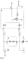
Figur 1- ein Bordnetz eines Kraftfahrzeugs mit einer ersten Vorrichtung in einem Blockschaltbild,
Figur 2- die Steuereinrichtung der ersten Vorrichtung in einem Blockschaltbild, und
Figur 3- ein Bordnetz eines Kraftfahrzeugs mit einer zweiten Vorrichtung in einem Blockschaltbild,
- Figur 4
- die Steuereinrichtung der zweiten Vorrichtung in einem Blockschaltbild, und
- Figur 5
- die Nachladeeinrichtung der Notstromquelle der zweiten Vorrichtung in einem Blockschaltbild detailiert dargestellt.
- FIG. 1
- an electrical system of a motor vehicle with a first device in a block diagram,
- FIG. 2
- the control device of the first device in a block diagram, and
- FIG. 3
- an electrical system of a motor vehicle with a second device in a block diagram,
- FIG. 4
- the control device of the second device in a block diagram, and
- FIG. 5
- the recharging the emergency power source of the second device shown in detail in a block diagram.
Gemäß den Figuren umfasst ein Bordnetz eines Kraftfahrzeugs ein erstes und ein zweites Energiesystem Esys1, Esys2, sowie eine im negativen Strompfad des Bordnetzes angeordnete Vorrichtung V. Die Energiesysteme Esys1, Esys2 in diesem beispielhaften Bordnetz sind voneinander nicht potential getrennt, also sind zueinander potentialgebunden.According to the figures, a vehicle electrical system of a motor vehicle comprises a first and a second energy system Esys1, Esys2, as well as a device V arranged in the negative current path of the vehicle electrical system. The energy systems Esys1, Esys2 in this exemplary vehicle electrical system are not isolated from one another, ie they are non-electrically connected.
Die Vorrichtung V kann aber auch in einem Bordnetz mit voneinander potential getrennten Energiesystemen Esys1, Esys2 angeordnet werden. Ebenso kann die Vorrichtung V nicht nur im negativen Strompfad des Bordnetzes, sondern auch im positiven Strompfad des Bordnetzes angeordnet werden.
Das erste Energiesystem Esys1 umfasst einen Generator G, einen Energiespeicher ES1 und eine Gruppe von Stromverbrauchern wie z. B Lampen oder Motorstarter, welche zusammengefasst Systemlast LA genannt werden.
Der vorzugsweise als Drehstrommaschine mit nachgeschalteter Gleichrichterschaltung ausgebildete Generator G dient als Energiewandler zum Umwandeln der kinetischen Energie vom Fahrzeug in die elektrische Energie und zugleich als Energiequelle zum Versorgen der Systemlast LA mit der elektrischen Energie.
Der Energiespeicher ES1, also der erste Energiespeicher im Bordnetz, speichert die vom Generator G umgewandelte elektrische Energie und versorgt die Systemlast LA mit der gespeicherten elektrischen Energie.
Das zweite Energiesystem Esys2 des Bordnetzes umfasst einen weiteren also zweiten Energiespeicher ES2 des Bordnetzes, welcher vorzugsweise als Doppelschichtkondensator ausgebildet ist und ebenfalls zum Versorgen der Systemlast LA mit der gespeicherten elektrischen Energie dient.
Die zwei Energiesysteme Esys1, Esys2 weisen unterschiedliche Nominalspannungen Vsys1, Vsys2 als Systemspannungen auf.The device V can also be arranged in a vehicle electrical system with separate potential energy systems Esys1, Esys2. Likewise, the device V can be arranged not only in the negative current path of the electrical system, but also in the positive current path of the electrical system.
The first energy system Esys1 comprises a generator G, an energy storage ES1 and a group of electricity consumers such. B lamps or motor starters, which are collectively called system load LA.
The preferably designed as a three-phase machine with downstream rectifier circuit generator G is used as energy converter for converting the kinetic energy from the vehicle into the electrical energy and at the same time as an energy source for supplying the system load LA with the electrical energy.
The energy storage ES1, ie the first energy storage in the electrical system, stores the electrical energy converted by the generator G and supplies the system load LA with the stored electrical energy.
The second energy system Esys2 the on-board network includes another so second energy storage ES2 of the electrical system, which is preferably designed as a double-layer capacitor and also serves to supply the system load LA with the stored electrical energy.
The two energy systems Esys1, Esys2 have different nominal voltages Vsys1, Vsys2 as system voltages.
Der erste Energiespeicher ES1 mit bspw. einer oder mehreren 12V-Batterien oder Li-Zellen in einer Gruppenschaltung dient als Energie- bzw. Stromquelle für die Normalverbraucher der Systemlast LA wie z. B. Lichtmaschine. Der zweite Energiespeicher ES2 dient als Energie- bzw. Stromquelle für die für Hochstromverbraucher der Systemlast LA wie z. B. Motorstarter.The first energy storage ES1 with, for example, one or more 12V batteries or Li cells in a group circuit serves as an energy or power source for the normal load of the system load LA such. B. alternator. The second energy storage ES2 serves as an energy or power source for the high-current consumers of the system load LA such. B. motor starter.
Die Steuerung des Stromflusses zwischen diesen beiden Energiesystemen wird von einer Vorrichtung V bzw. V` bewirkt.The control of the current flow between these two energy systems is effected by a device V or V`.
Die Vorrichtung V, V' weist eine erste Nachladeeinrichtung NL1, mit der die Vorrichtung V, V' den zweiten Energiespeicher ES2 mit der elektrischen Energie von dem ersten Energiespeicher ES1 bzw. dem Generator G auflädt. Bedarfsweise lädt die Vorrichtung V, V' auch den ersten Energiespeicher ES1 mit der elektrischen Energie vom zweiten Energiespeicher ES2 auf. Hierzu weist die Nachladeeinrichtung NL1 einen DC/DC-Wandler auf zur Umwandlung der Systemspannung Vsys1 des energiegebenden Energiesystems Esys1 in die Systemspannung Vsys2 des aktuell zu ladenden Energiespeichers Esys2, um den Energiespeicher Esys2 auf den gewünschten Ladezustand aufzuladen.The device V, V 'has a first recharging device NL1, with which the device V, V' charges the second energy store ES2 with the electrical energy from the first energy store ES1 or the generator G. If necessary, the device V, V 'also charges the first energy store ES1 with the electrical energy from the second energy store ES2. For this purpose, the recharging device NL1 has a DC / DC converter for converting the system voltage Vsys1 of the energy-giving energy system Esys1 into the system voltage Vsys2 of the energy store Esys2 currently to be charged, in order to charge the energy store Esys2 to the desired state of charge.
Zur Steuerung des Stromflusses von den beiden Energiespeichern ES1, ES2 zur Systemlast LA weist die Vorrichtung V, V' einen ersten und einen zweiten voneinander unabhängig steuerbaren Schalter S1, S2 auf, welche bspw. als selbstsperrende MOSFET ausgebildet sind und über eine am jeweiligen Gate-Anschluss GS angelegte Gatespannung gesteuert ein-/geöffnet werden. Die Einstellung der Gatespannung des jeweiligen Schalters S1, S2, somit die Ansteuerung des jeweiligen Schalters S1, S2 erfolgt über eine erste und eine zweite Steuereinrichtung SE1, SE1' bzw. SE2, welche ausgangsseitig mit den Gate-Anschlüssen des jeweiligen Schalters S1, S2 elektrisch verbunden sind.In order to control the current flow from the two energy stores ES1, ES2 to the system load LA, the device V, V 'has a first and a second independently controllable switch S1, S2 which, for example, are designed as normally-off MOSFETs and which are connected to the gate Connection GS applied gate voltage controlled / opened. The adjustment of the gate voltage of the respective switch S1, S2, thus the activation of the respective switch S1, S2 via a first and a second control device SE1, SE1 'and SE2, which on the output side with the gate terminals of the respective switch S1, S2 electrically are connected.
Mit dem ersten Schalter S1 verbindet bzw. trennt die Vorrichtung V, V' den ersten Energiespeicher ES1 des ersten Energiesystems Esys1 mit der Systemlast LA elektrisch.With the first switch S1, the device V, V 'electrically connects or disconnects the first energy store ES1 of the first energy system Esys1 with the system load LA.
Um den ersten Energiespeicher ES1 mit der Systemlast LA elektrisch zu verbinden, schließt die Vorrichtung V, V' den ersten Schalter S1. Zur Trennung der elektrischen Verbindung zwischen dem ersten Energiespeicher ES1 und der Systemlast LA öffnet die Vorrichtung V, V' den ersten Schalter S1.In order to electrically connect the first energy store ES1 to the system load LA, the device V, V 'closes the first switch S1. To disconnect the electrical connection between the first energy store ES1 and the system load LA, the device V, V 'opens the first switch S1.
In einem nominalen Systemzustand im Bordnetz werden die Stromverbraucher LA im Bordnetz durch Schließen des ersten Schalters S1 von dem Generator G und dem ersten Energiespeicher ES1 des ersten Energiesystems Esys1 mit Strom versorgt. In diesem nominalen Zustand halten der Generator G und der erste Energiespeicher ES1 weitgehend im Bordnetz eine stabile Netzspannung aufrecht.In a nominal system state in the electrical system, the power consumers LA in the vehicle electrical system are supplied with power by closing the first switch S1 from the generator G and the first energy store ES1 of the first energy system Esys1. In this nominal state, the generator G and the first energy storage ES1 largely maintain a stable mains voltage in the electrical system.
In einem nicht nominalen Systemzustand, wobei der Stromverbrauch durch Schließen eines oder mehrerer Hochstromverbraucher wie z. B. Motorstarter kurzfristig stark ansteigt, können der Generator G und der erste Energiespeicher ES1 allein eine stabile Netzspannung im Bordnetz nicht mehr weiter aufrecht halten.In a non-nominal system state, the power consumption by closing one or more high-current consumers such. B. motor starter in the short term increases sharply, the generator G and the first energy storage ES1 alone can no longer maintain a stable line voltage in the electrical system.
In diesem nicht nominalen Zustand muss das zweite Energiesystem Esys2 mit dem zweiten Energiespeicher ES2 ins Bordnetz geschlossen bzw. eingespeist werden.In this non-nominal state, the second energy system Esys2 with the second energy storage ES2 must be closed or fed into the electrical system.
Dies geschieht durch bestimmtes Betätigen der beiden Schalter S1, S2 der Vorrichtung V, V'. Mit dem ersten und zweiten Schalter S1, S2 verbindet bzw. trennt die Vorrichtung das zweite Energiesystem Esys2 bzw. den zweiten Energiespeicher ES2 des zweiten Energiesystems Esys2 mit dem ersten Energiesystem Esys1 bzw. dem ersten Energiespeicher ES1 sowie der Systemlast LA des ersten Energiesystems Esys1 elektrisch.This is done by certain actuation of the two switches S1, S2 of the device V, V '. The device electrically connects or disconnects the second energy system Esys2 or the second energy store ES2 of the second energy system Esys2 with the first energy system Esys1 or the first energy store ES1 and the system load LA of the first energy system Esys1, respectively, with the first and second switches S1, S2.
Durch zeitgleiches Schließen des zweiten Schalters S2 und Öffnen des ersten Schalters S1 verbindet die Vorrichtung V, V` das zweite Energiesystem Esys2 bzw. den zweiten Energiespeicher ES2 des zweiten Energiesystems Esys2 mit dem ersten Energiesystem Esys1 bzw. dem ersten Energiespeicher ES1 sowie der Systemlast LA des ersten Energiesystems ES1 elektrisch und hält somit die Netzspannung im Bordnetz aufrecht.By simultaneously closing the second switch S2 and opening the first switch S1, the device V, V` connects the second energy system Esys2 or the second energy store ES2 of the second energy system Esys2 with the first energy system Esys1 or the first energy store ES1 and the system load LA of the second first power system ES1 electric and thus maintains the mains voltage in the electrical system.
Durch Öffnen des zweiten Schalters S2 trennt die Vorrichtung V das zweite Energiesystem Esys2 bzw. den zweiten Energiespeicher ES2 von dem ersten Energiesystem Esys1 bzw. von dem ersten Energiespeicher ES1 sowie der Systemlast LA.By opening the second switch S2, the device V separates the second energy system Esys2 or the second energy store ES2 from the first energy system Esys1 or from the first energy store ES1 and the system load LA.
Neben der ersten Nachladeeinrichtung NL1, den beiden Schaltern S1, S2 weist die Vorrichtung V, V' ferner eine Steuereinrichtung SE1, SE1' zum Steuern des ersten Schalters 1, einen wiederaufladbaren Akkumulator als Notstromquelle NQ, eine zweite Nachladeeinrichtung NL2, NL2' für die Notstromquelle NQ, eine Diagnoseeinrichtung DN zum Diagnostizieren der Funktionalität bzw. zur Überwachung des Ladezustandes der Notstromquelle NQ auf.In addition to the first recharging device NL1, the two switches S1, S2, the device V, V 'further comprises a control device SE1, SE1' for controlling the
Ferner weist die Vorrichtung V des ersten Bordnetzes in den
Die zwei Spannungsumwandlungseinrichtungen SW1, SW3 können allersamt als DC/DC-Wandler gleichen Typs mit manuell und voneinander unabhängig einstellbaren Umwandlungskoeffizienten ausgebildet sein, aber auch als DC/DC-Wandler unterschiedlichen Typs mit unterschiedlichen Umwandlungskoeffizienten.The two voltage conversion devices SW1, SW3 can be designed overall as DC / DC converters of the same type with manually and independently adjustable conversion coefficients, but also as DC / DC converters of different types with different conversion coefficients.
Die Steuerung des ersten MOSFET-Schalters S1 erfolgt durch die Steuereinrichtung SE1, welche als Ausgangssignal am Ausgang K24 der Einrichtung SE1 die Gatespannung Vgs1 für den Schalter S1 bereitstellt. Mit zwei Signaleingängen K21, K23 ist die Steuereinrichtung SE1 mit dem jeweiligen Ausgang der beiden Spannungsumwandlungseinrichtungen SW1, SW3 elektrisch verbunden, welche wiederum eingangsseitig mit dem jeweiligen positiven Anschluss des ersten Energiespeichers Esys1 und der Notstromquelle NQ elektrisch verbunden sind.The control of the first MOSFET switch S1 is effected by the control device SE1, which provides the gate voltage Vgs1 for the switch S1 as an output signal at the output K24 of the device SE1. With two signal inputs K21, K23, the control device SE1 is electrically connected to the respective output of the two voltage conversion devices SW1, SW3, which in turn are electrically connected on the input side to the respective positive terminal of the first energy storage Esys1 and the emergency power source NQ.
Die Spannungsumwandlung bei den beiden Spannungsumwandlungseinrichtungen SW1, SW3 erfolgt prozentual, also die Ausgangsspannung Ua verhält sich proportional zu der Eingangsspannung Ua, wobei die Verhältnisse der Ausgangsspannungen Ua zu den jeweiligen Eingangsspannungen Ue bei allen beiden Spannungsumwandlungseinrichtungen SW1, SW3 durch Einstellen der einstellbaren Umwandlungskoeffizienten k regelbar sind.The voltage conversion in the two voltage conversion devices SW1, SW3 is carried out as a percentage, that is, the output voltage Ua is proportional to the input voltage Ua, wherein the ratios of the output voltages Ua to the respective input voltages Ue in all two voltage conversion devices SW1, SW3 are adjustable by adjusting the adjustable conversion coefficients k ,
Die Ausgangsspannungen von den beiden Spannungsumwandlungseinrichtungen SW1, SW3 werden von der Steuereinrichtung SE1 an den Gate-Anschluss GS1 des ersten Schalters S1 weitergeleitet.The output voltages from the two voltage conversion devices SW1, SW3 are forwarded by the control device SE1 to the gate terminal GS1 of the first switch S1.
Hierzu weist die Steuereinrichtung SE1 zwei Dioden D1, D2 auf, welche mit ihrem Anode-Anschluss mit dem jeweiligen Ausgang der Spannungsumwandlungseinrichtungen SW3, SW1 und mit ihrem Kathode-Anschluss mit dem Gate-Anschluss GS1 des ersten Schalters S1 elektrisch verbunden sind, und den Strom von den Ausgängen der jeweiligen Spannungsumwandlungseinrichtungen SW3, SW1 zum Gate-Anschluss GS1 des ersten Schalters S1 hin leiten und umgekehrt sperren.For this purpose, the control device SE1 has two diodes D1, D2, which are electrically connected with their anode terminal to the respective output of the voltage conversion devices SW3, SW1 and with its cathode terminal to the gate terminal GS1 of the first switch S1, and the current from the outputs of the respective voltage conversion means SW3, SW1 to the gate terminal GS1 of the first switch S1 out and reverse reverse.
Ferner weist die Steuereinrichtung SE1 zwischen dem Knoten K24 also zwischen dem Gate-Anschluss des ersten Schalters S1 und dem Massenpotential einen dritten steuerbaren, ebenfalls als selbstsperrrender MOSFET ausgeführten Schalter S3 auf.Furthermore, the control device SE1 between the node K24 so between the gate terminal of the first switch S1 and the ground potential on a third controllable, also designed as a self-blocking MOSFET switch S3.
Der Gate-Anschluss dieses dritten Schalters S3 wird von einer zwischengeschalteten Steuereinheit SH gesteuert, wobei diese Steuereinheit SH den Stromfluss im Bordnetz (bspw. am ersten Schalter S1) überwacht und bei stark ansteigendem Stromfluss bzw. bei Überschreiten des Stromwertes im Bordnetz (bzw. am ersten Schalter S1) über einen vorgegebenen Sollstromwert den dritten Schalter S3 schließt und so die Gatespannung Vgs1 des ersten Schalters S1 auf den Massepotential legt. Solange aber der Bordnetzstrom unter den Sollstromwert liegt, hält die Steuereinheit SH den dritten Schalter S3 in einem geöffneten Zustand und die Gatespannung Vgs1 des ersten Schalters S1 auf das Spannungsniveau der Ausgangsspannung der Spannungsumwandlungseinrichtungen SW1, SW3.The gate terminal of this third switch S3 is controlled by an intermediate control unit SH, this control unit SH monitors the current flow in the electrical system (eg at the first switch S1) and at strongly increasing current flow or when exceeding the current value in the electrical system (or first switch S1) closes the third switch S3 via a predetermined nominal current value and thus sets the gate voltage Vgs1 of the first switch S1 to the ground potential. However, as long as the vehicle electrical system current is below the target current value, the control unit SH holds the third switch S3 in an open state and the gate voltage Vgs1 of the first switch S1 to the voltage level of the output voltage of the voltage conversion devices SW1, SW3.
In einem nominalen fehlerfreien Systemzustand im Bordnetz ist die Systemspannung Vsys1 des ersten Energiesystems ES1 bzw. die Spannung Ves1 am ersten Energiespeicher ES1 höher als oder gleich hoch wie eine für einen stabilen Systemzustand im Bordnetz erforderliche Mindestspannung (Nominalspannung).In a nominal fault-free system state in the electrical system, the system voltage Vsys1 of the first energy system ES1 or the voltage Ves1 at the first energy store ES1 is higher than or equal to a minimum voltage required for a stable system state in the electrical system (nominal voltage).
In diesem Fall ist die Ausgangsspannung von der ersten Spannungsumwandlungseinrichtung SW1, welche unverändert von der ersten Diode D1 der Steuereinrichtung SE1 zum Gate-Anschluss GS1 weitergeleitet wird, höher als die zum Schließen des Schalters S1 erforderliche Soll-Gatespannung Vsgs1, sodass der erste Schalter S1 geschlossen wird bzw. im geschlossenen Zustand gehalten wird und den Strom vom ersten Energiespeicher ES1 zu der Systemlast LA leitet.In this case, the output voltage from the first voltage converting device SW1, which is forwarded unchanged from the first diode D1 of the controller SE1 to the gate terminal GS1, is higher than the target gate voltage Vsgs1 required for closing the switch S1, so that the first switch S1 is closed is held in the closed state and the current from the first energy storage ES1 to the system load LA directs.
Da in diesem nominalen Systemzustand der Strom im Bordnetz unter den vorgegebenen Sollstromwert liegt und die Systemspannung Vsys1 des ersten Energiesystems oberhalb eines vorgegebenen Sollspannungswertes liegt, öffnet die Steuereinheit SH den dritten Schalter S3 bzw. hält den dritten Schalter S3 in einem geöffneten Zustand, sodass die Gatespannung Vgs1 des ersten Schalters S1 auf das Spannungsniveau der Ausgangsspannung der Spannungsumwandlungseinrichtung SW1 gehalten wird.Since in this nominal system state, the current in the electrical system is below the predetermined target current value and the system voltage Vsys1 of the first energy system is above a predetermined target voltage value, the control unit SH opens the third switch S3 and holds the third switch S3 in an open state, so that the gate voltage Vgs1 of the first switch S1 is maintained at the voltage level of the output voltage of the voltage conversion device SW1.
In diesem Systemzustand hält die zweite Steuereinrichtung SE2 den zweiten Schalter S2 im geöffneten Zustand.In this system state, the second control device SE2 holds the second switch S2 in the opened state.
In einem nicht-nominalen aber weiterhin fehlerfreien Systemzustand im Bordnetz steigt der Strom im ersten Energiesystem Esys1 steil an bzw. fällt die Systemspannung Vsys1 rapid ab.In a non-nominal but still error-free system state in the electrical system, the current in the first energy system Esys1 rises steeply or the system voltage Vsys1 drops rapidly.
Diese Veränderung des Stromes oder der Spannung wird von der Steuereinheit SH in der Steuereinrichtung SE1 erfasst. Die Steuereinheit SH setzt dann deren Ausgangsspannung auf ein zum Schließen des dritten Schalters S3 erforderliches Spannungsniveau und schließt so den dritten Schalter S3.This change in the current or the voltage is detected by the control unit SH in the control device SE1. The control unit SH then sets its output voltage to a required to close the third switch S3 voltage level and thus closes the third switch S3.
Demzufolge wird der Gate-Anschluss GS1 des ersten Schalters S1 auf den Massepotential gelegt. Folglich wird der erste Schalter S1 geöffnet und der Stromfluss vom ersten Energiespeicher ES1 durch diesen ersten Schalter S1 hin zur Systemlast LA unterbrochen.As a result, the gate terminal GS1 of the first switch S1 is set at the ground potential. Consequently, the first switch S1 is opened and the current flow from the first energy store ES1 is interrupted by this first switch S1 toward the system load LA.
Zeitgleich schließt die zweite Steuereinrichtung SE2 den zweiten Schalter S2 und verbindet so das zweite Energiesystem Esys2 bzw. den zweiten Energiespeicher ES2 mit dem ersten Energiesystem Esys1 bzw. mit dem ersten Energiespeicher ES1 und der Systemlast LA. So wird ein Strompfad vom ersten Energiespeicher ES1 über den zweiten Schalter S2 zum zweiten Energiespeicher ES2 und anschließend zur Systemlast LA hergestellt und die Netzspannung dank dem zweiten Energiespeicher ES2 auf einen zum Betreiben der Systemlast LA erforderlichen Spannungspotential gehalten.At the same time, the second control device SE2 closes the second switch S2 and thus connects the second energy system Esys2 or the second energy store ES2 to the first energy system Esys1 or to the first energy store ES1 and the system load LA. Thus, a current path from the first energy store ES1 is established via the second switch S2 to the second energy store ES2 and then to the system load LA, and the grid voltage is kept at a voltage potential required to operate the system load LA thanks to the second energy store ES2.
Tritt im Bordnetz ein Systemfehler durch bspw. Verpolung des ersten Energiespeichers ES1 auf, so bricht die Systemspannung Vsys1 am ersten Energiesystem Esys1 bzw. die Spannung am ersten Energiespeicher ES1 unkontrolliert ab, ohne dabei ein Stromanstieg im Bordnetz verzeichnet wird. In diesem Fall fällt die Ausgangsspannung der ersten Spannungsumwandlungseinrichtung SW1 unter die Soll-Gatespannung Vsgs ab.If a system fault occurs in the vehicle electrical system due to, for example, reverse polarity of the first energy store ES1, then the system voltage Vsys1 on the first energy system Esys1 or the voltage on the first energy store ES1 breaks down in an uncontrolled manner without a current increase in the vehicle electrical system being recorded. In this case, the output voltage of the first voltage conversion device SW1 falls below the target gate voltage Vsgs.
Folglich droht der erste Schalter S1 zu öffnen und der Stromfluss vom ersten Energiespeicher ES1 über diesen ersten Schalter S1 zur Systemlast LA unterbrochen zu werden.Consequently, the first switch S1 threatens to open and the current flow from the first energy store ES1 to be interrupted via this first switch S1 to the system load LA.
Da jedoch kein rapid ansteigender Stromfluss erfasst wurde, schalten die zweite Steuereinrichtung SE2 und die Steuereinheit SH der ersten Steuereinrichtung SE1 den zweiten und dritten Schalter S2, S3 nicht ein.However, since no rapid rising current flow was detected, the second controller SE2 and the control unit SH of the first controller SE1 do not turn on the second and third switches S2, S3.
Außerdem, weil die Steuereinheit SH von dem ersten Energiespeicher ES1 mit dem Strom versorgt wird, wird die Steuereinheit SH beim Abbrechen der Systemspannung beim ersten Energiespeicher ES1 aufgrund der fehlenden Betriebsspannung nicht mehr funktionieren. Demzufolge fällt die Steuerspannung also die Gatespannung für den dritten Schalter S3 aus und öffnet der als selbstsperrender MOSFET ausgebildete dritte Schalter S3 automatisch.In addition, because the control unit SH is powered by the first energy storage ES1 with the power, the control unit SH will no longer work when canceling the system voltage at the first energy storage ES1 due to the lack of operating voltage. As a result, the control voltage thus drops the gate voltage for the third switch S3 and the third switch S3 designed as a self-blocking MOSFET opens automatically.
Durch den Abfall der Systemspannung Vsys1 fällt auch die Betriebsspannung an der zweiten Steuerungseinrichtung weg und somit auch die Gatespannung für den zweiten Schalter S2. Der als selbstsperrende MOSFET ausgebildete zweite Schalter S2 öffnet so automatisch. Dies ist gewünscht, damit das zweite Energiesystem Esys2 bzw. der zweite Energiespeicher ES2 nicht an das fehlerhafte Bordnetz angeschlossen wird.Due to the drop in the system voltage Vsys1, the operating voltage at the second control device also drops and thus also the gate voltage for the second switch S2. The trained as a self-blocking MOSFET second switch S2 opens automatically. This is desired so that the second energy system Esys2 or the second energy storage ES2 is not connected to the faulty vehicle electrical system.
Im fehlerhaften ersten Energiesystem Esys1 bspw. am Generator G entsteht jedoch eine parasitäre Strominjektion Ii, welche durch den MOSFET internen parasitären Diodenpfad DS2 des geöffneten zweiten Schalters S2 hindurch zum zweiten Energiesystem Esys2 hin unkontrolliert fließen und so einerseits zu Überhitzen des zweiten Schalters S2 und andererseits zu unkontrolliertem Überladen des zweiten Energiespeichers ES2 führen kann.However, a parasitic current injection Ii, which flows through the MOSFET internal parasitic diode path DS2 of the opened second switch S2 through to the second energy system Esys2, flows uncontrolled in the faulty first energy system Esys1, for example, to overheat of the second switch S2 and on the other hand to Uncontrolled overcharging of the second energy storage ES2 can lead.
Diese Strominjektion Ii kann einfacherweise mithilfe vom Strompfad durch den geschlossenen ersten Schalter S1 zur Masse abgeführt und unschädlich gemacht werden.This current injection Ii can simply be dissipated to ground by means of the current path through the closed first switch S1 and made harmless.
Beim Ausbleiben der Spannung Ves1 in diesem fehlerhaften Systemzustand bleibt der als selbstsperrender MOSFET ausgeführte erste Schalter S1 jedoch dank der Notstromquelle NQ und dem Steuerpfad von der Notstromquelle über die zweite Diode D3 in der Steuereinrichtung SE1 hin zum Gate-Anschluss des ersten Schalters S1 weiterhin geschlossen und leitet so die parasitäre Strominjektion Ii zur Masse ab.
Dies geschieht dadurch, dass die Notstromquelle NQ unabhängig vom Systemzustand Strom liefert und dank der nachgeschalteten Spannungsumwandlungseinrichtung SW3, welche die Spannung an der Notstromquelle NQ auf eine zum Schließen des ersten Schalters S1 erforderliche Gatespannung umwandelt bzw. erhöht, der erste Schalter S1 auch beim Ausbleiben der Spannung vom ersten Energiespeicher ES1 weiterhin von der Spannung der Notstromquelle NQ gesteuert geschlossen bzw. im geschlossenen Zustand gehalten wird.
Da beim Abbrechen der Systemspannung des ersten Energiesystems ES1 bzw. der Spannung am ersten Energiespeicher ES1 keine Spannung am Gate-Anschluss des dritten Schalters S3 anliegt, öffnet der selbstsperrende dritte Schalter S3 automatisch und somit wird der Gate-Anschluss des ersten Schalters S1 auch nicht mit der Masse kurzgeschlossen.
Dadurch wird der erste Schalter S1 beim Auftreten eines Systemfehlers beim ersten Energiesystem Esys1 geschlossen bzw. in einem geschlossenen Zustand gehalten und die parasitäre Strominjektion Ii vom ersten Energiesystem Esys1 durch diesen ersten Schalter S1 zur Masse abgeführt und unschädlich gemacht.
In der Folge daraus kann ein parasitärer Lade- oder Überladevorgang vom zweiten Energiespeicher ES2 und eine Systemüberhitzung am zweiten Schalter S2 bzw. innerhalb der Vorrichtung V verhindert werden. Ferner kann das gesamte Bordnetz trotz des Systemfehlers in einem Sicherheitszustand (Safe-State) gehalten werden.In the absence of the voltage Ves1 in this faulty system state of running as a self-locking MOSFET first switch S1 remains closed thanks to the emergency power source NQ and the control path from the emergency power source via the second diode D3 in the controller SE1 to the gate terminal of the first switch S1 and thus derives the parasitic current injection Ii to ground.
This happens because the emergency power source NQ provides power regardless of the system state and thanks to the downstream voltage conversion device SW3, which converts the voltage at the emergency power source NQ to a required to close the first switch S1 gate voltage or increases, the first switch S1 even in the absence of Voltage from the first energy storage ES1 further controlled by the voltage of the emergency power source NQ closed or held in the closed state.
Since no voltage is applied to the gate terminal of the third switch S3 when the system voltage of the first energy system ES1 or the voltage ES1 is disconnected, the normally-off third switch S3 opens automatically, and thus the gate terminal of the first switch S1 does not become too shorted to ground.
As a result, the first switch S1 is closed or held in a closed state when a system fault occurs in the first energy system Esys1, and the parasitic current injection Ii from the first energy system Esys1 is dissipated to ground by this first switch S1 and rendered harmless.
As a result, parasitic charging or overcharging from the second energy storage ES2 and system overheating at the second switch S2 or within the device V can be prevented. Furthermore, the entire vehicle electrical system can be kept in a safe state despite the system error.
Die Notstromquelle NQ kann von dem ersten Energiesystem Esys1 bzw. von dem ersten Energiespeicher ES1 des ersten Energiesystems Esys1 in einem nominalen fehlerfreien Systemzustand mit dem Strom aufgeladen werden. Der Ladezustand der Notstromquelle NQ bzw. der Ladevorgang bei der Notstromquelle NQ kann von der Diagnoseeinrichtung DN überwacht und geregelt werden.The emergency power source NQ can be charged from the first energy system Esys1 or from the first energy storage ES1 of the first energy system Esys1 in a nominal fault-free system state with the current. The state of charge of the emergency power source NQ or the charging process with the emergency power source NQ can be monitored and controlled by the diagnostic device DN.
Die in den
Hierzu weist die Vorrichtung V` eine weitere Spannungsumwandlungseinrichtung SW2, welche die Spannung Vsys2 des zweiten Energiesystems Esys2 bzw. die Spannung Ves2 des zweiten Energiespeichers ES2 in einer Steuerspannung umwandelt. Diese umgewandelte Steuerspannung wird von einer weiteren Diode D3 an den Gate-Anschluss GS1 des ersten Schalters S1 weitergeleitet und steuert den ersten Schalter S1 als Gatespannung Vgs1.For this purpose, the device V 'has a further voltage conversion device SW2, which converts the voltage Vsys2 of the second energy system Esys2 or the voltage Ves2 of the second energy store ES2 in a control voltage. This converted control voltage is forwarded by a further diode D3 to the gate terminal GS1 of the first switch S1 and controls the first switch S1 as a gate voltage Vgs1.
So ist ein redundanter Steuerpfad für den ersten Schalter S1 geschaffen, welcher im fehlerhaften Zustand beim ersten Energiesystem Esys1 neben dem Steuerpfad von der Notstromquelle NQ auch zum Schließen bzw. Halten des ersten Schalters S1 im geschlossenen Zustand dient.Thus, a redundant control path is provided for the first switch S1, which in the fault state at the first energy system Esys1 next to the control path from the emergency power source NQ also serves to close or hold the first switch S1 in the closed state.
Die Notstromquelle NQ kann in diesem Fall sowohl von dem ersten als auch von dem zweiten Energiespeicher ES1, ES2 mit dem Strom aufgeladen werden. Hierzu weist die Nachladeeinrichtung NL2' jeweils einen Anschluss K31, K32 zu dem jeweiligen Energiespeicher ES1, ES2 auf. Zwischen dem jeweiligen Eingangsanschluss K31, K32 und dem Ausgangsanschluss K33 weist die Nachladeeinrichtung NL2' jeweils eine Diode und einen Widerstand umfassende Nachladeeinheit auf.The emergency power source NQ can be charged in this case, both from the first and the second energy storage ES1, ES2 with the current. For this purpose, the recharging device NL2 'each have a connection K31, K32 to the respective energy store ES1, ES2. Between the respective input terminal K31, K32 and the output terminal K33, the recharging device NL2 'has in each case a diode and a recharging unit comprising a resistor.
- Esys1, Esys2Esys1, Esys2
- Erstes, zweites EnergiesystemFirst, second energy system
- ES1, ES2ES1, ES2
- Erster, zweiter EnergiespeicherFirst, second energy storage
- V, V'V, V '
- Vorrichtungcontraption
- GG
- Generatorgenerator
- DGDG
- Parasitäre Diode im GeneratorParasitic diode in the generator
- LALA
- Systemlastsystem load
- S1, S2, S3S1, S2, S3
- Erster, zweiter, dritter SchalterFirst, second, third switch
- DS2DS2
- Parasitärer Diodenpfad im zweiten Schalter S2Parasitic diode path in the second switch S2
- NQNQ
- Notstromquelleemergency power source
- NL1, NL2, NL2'NL1, NL2, NL2 '
- Nachladeeinrichtungreloading
- DNDN
- Diagnoseeinrichtungdiagnostic device
- SW1, SW2, SW3, SW4SW1, SW2, SW3, SW4
- SpannungsumwandlungseinrichtungVoltage converter
- SE1, SE2SE1, SE2
- Steuereinrichtungcontrol device
- SHSH
- Steuereinheitcontrol unit
- D1, D2, D3D1, D2, D3
- Diode, elektrisches VentilDiode, electric valve
- K1, K2, K3, K4K1, K2, K3, K4
- Anschluss der Vorrichtung V, V'Connection of the device V, V '
- K21, K22, K23, K24K21, K22, K23, K24
- Anschluss der Steuereinrichtung SE1Connection of the control device SE1
- K31, K32, K33K31, K32, K33
- Anschluss der Nachladeeinrichtung NL2'Connection of the recharging device NL2 '
- GS1GS1
- Gate-Anschluss des ersten Schalters S1Gate terminal of the first switch S1
Claims (9)
- On-board system for a vehicle, comprising the following features:- a first current path, comprising:∘ at least one current consumer (LA),∘ a first energy store (ES1), and∘ a first self-locking switch (S1) controllable by means of a first control voltage,wherein, in a closed state of the first switch (S1), the at least one current consumer (LA) is electrically connectable to the first energy store (ES1),- a second current path, comprising:∘ the at least one current consumer (LA),∘ the first (ES1) and a second energy store (ES2), and∘ a second switch (S2) controllable by means of a second control voltage,wherein, in a closed state of the second switch (S2), the at least one current consumer (LA) is electrically connectable to the first (ES1) and the second energy store (ES2),- a control arrangement (SE1) for closing the first switch (S1) or for holding the first switch (S1) in the closed state when the voltage provided by the energy store (ES1) supplying the first switch (S1) falls below a minimum voltage threshold value necessary to close the first switch (S1) or to hold the first switch (S1) in the closed state.
- On-board system according to Claim 1, comprising an emergency power source (NQ) for providing the voltage necessary to close the first switch (S1) or to hold the first switch (S1) in the closed state, wherein the control arrangement (SE1) for closing the first switch (S1) or for holding the first switch (S1) in the closed state is embodied with the voltage provided by the emergency power source (NQ).
- On-board system according to one of the preceding claims, wherein the first energy store (ES1) and the second energy store (ES2) are designed to be electrically connectable at the same time to the current consumer (LA) only in the open state of the first switch (S1) and in the simultaneously closed state of the second switch (S2).
- On-board system according to one of the preceding claims, wherein the control arrangement (SE1) is designed to close the first switch (S1) and to hold the first switch (S1) in the closed state with the voltage provided by the emergency power source (NQ) only in the open state of the second switch (S2).
- On-board system according to one of preceding Claims 2 to 4, wherein the control arrangement (SE1) is designed to close the first switch (S1) and to hold the first switch (S1) in the closed state selectively with the voltage of the emergency power source (NQ) or with the voltage of the first energy store (ES1) or of the second energy store (ES2) in a manner dependent on the voltage of the emergency power source (NQ) and dependent on at least one of the voltages of the first energy store (ES1) and of the second energy store (ES2).
- On-board system according to one of the preceding claims, wherein- the first switch (S1) comprises a control connection (GS1) for the control voltage, and- the control arrangement (SE1) comprises∘ a first electric valve (D1), in particular a diode, arranged between the control connection (GS1) of the first switch (S1) and the emergency power source (NQ), and conductive towards the control connection (GS1) of the first switch (S1) and in the opposite direction blocking, and/or∘ a second electric valve (D2), in particular a diode, arranged between the control connection (GS1) of the first switch (S1) and the first energy store (ES1), and conductive towards the control connection (GS1) of the first switch (S1) and in the opposite direction blocking, and/or∘ a third electric valve (D3), in particular a diode, arranged between the control connection (GS1), of the first switch (S1) and the second energy store (ES2), and conductive towards the control connection (GS1) of the first switch (S1) and in the opposite direction blocking.
- On-board system according to one of Claims 2 to 6, wherein- the emergency power source (NQ) is a rechargeable accumulator, and- the on-board system comprises, between the first energy store (ES1) and/or second energy store (ES2) and the emergency power source (NQ), a first recharging unit (NL2, NL21) and/or second recharging unit (NL22) for charging the emergency power source (NQ) with the power of the first energy store (ES1) and/or of the second energy store (ES2).
- On-board system according to one of the preceding claims, wherein- the control arrangement (SE1) comprises∘ a third controllable switch (S3) between the control connection (GS1) of the first switch (S1) and the ground potential,∘ a control unit (SH) for controlling the third switch (S3),- wherein said control unit (SH) is designed∘ to determine an effective current value at the current path from the first energy store (ES1) to the current consumer (LA), in particular at the first energy store (ES1),∘ to compare the effectively determined current value with a predefined target current value, and,∘ to close the third switch (S3) if the target current value is exceeded by the effectively determined current value 2nd to connect the control voltage of the first switch (S1) to ground potential.
- Vehicle, in particular motor vehicle, comprising an on-board system according to one of Claims 1 to 8.
Priority Applications (1)
| Application Number | Priority Date | Filing Date | Title |
|---|---|---|---|
| EP17156372.9A EP3239517B1 (en) | 2010-12-20 | 2011-12-12 | Device for controlling a current flow in an on-board supply system of a vehicle |
Applications Claiming Priority (2)
| Application Number | Priority Date | Filing Date | Title |
|---|---|---|---|
| DE102010063598A DE102010063598A1 (en) | 2010-12-20 | 2010-12-20 | Vehicle electrical system for a vehicle and device for controlling a current flow in a vehicle electrical system of a vehicle |
| PCT/EP2011/072414 WO2012084565A1 (en) | 2010-12-20 | 2011-12-12 | On-board system for a vehicle and device for controlling a current flow in an on-board system of a vehicle |
Related Child Applications (2)
| Application Number | Title | Priority Date | Filing Date |
|---|---|---|---|
| EP17156372.9A Division EP3239517B1 (en) | 2010-12-20 | 2011-12-12 | Device for controlling a current flow in an on-board supply system of a vehicle |
| EP17156372.9A Division-Into EP3239517B1 (en) | 2010-12-20 | 2011-12-12 | Device for controlling a current flow in an on-board supply system of a vehicle |
Publications (2)
| Publication Number | Publication Date |
|---|---|
| EP2655859A1 EP2655859A1 (en) | 2013-10-30 |
| EP2655859B1 true EP2655859B1 (en) | 2018-02-28 |
Family
ID=45315815
Family Applications (2)
| Application Number | Title | Priority Date | Filing Date |
|---|---|---|---|
| EP11794169.0A Active EP2655859B1 (en) | 2010-12-20 | 2011-12-12 | On-board system for a vehicle |
| EP17156372.9A Active EP3239517B1 (en) | 2010-12-20 | 2011-12-12 | Device for controlling a current flow in an on-board supply system of a vehicle |
Family Applications After (1)
| Application Number | Title | Priority Date | Filing Date |
|---|---|---|---|
| EP17156372.9A Active EP3239517B1 (en) | 2010-12-20 | 2011-12-12 | Device for controlling a current flow in an on-board supply system of a vehicle |
Country Status (4)
| Country | Link |
|---|---|
| US (1) | US9487089B2 (en) |
| EP (2) | EP2655859B1 (en) |
| DE (1) | DE102010063598A1 (en) |
| WO (1) | WO2012084565A1 (en) |
Families Citing this family (10)
| Publication number | Priority date | Publication date | Assignee | Title |
|---|---|---|---|---|
| DE102010063598A1 (en) | 2010-12-20 | 2012-06-21 | Continental Automotive Gmbh | Vehicle electrical system for a vehicle and device for controlling a current flow in a vehicle electrical system of a vehicle |
| DE102012200804A1 (en) * | 2012-01-20 | 2013-07-25 | Continental Automotive Gmbh | On-board network and method for operating a vehicle electrical system |
| WO2014205508A1 (en) * | 2013-06-28 | 2014-12-31 | Cap-Xx Limited | A control system for an automotive engine and a method of controlling an automotive engine |
| DE102013221579A1 (en) * | 2013-10-24 | 2015-04-30 | Zf Friedrichshafen Ag | Electronic device and method for operating an electronic device |
| DE102014208257A1 (en) * | 2014-04-30 | 2015-11-05 | Continental Automotive Gmbh | Stabilization circuit for a vehicle electrical system |
| CN104393565A (en) * | 2014-12-04 | 2015-03-04 | 京东方科技集团股份有限公司 | Over-temperature protection device, method and electrical equipment |
| JP6638616B2 (en) * | 2016-09-30 | 2020-01-29 | 株式会社デンソー | Power control device |
| JP6789780B2 (en) * | 2016-11-28 | 2020-11-25 | 株式会社 日立パワーデバイス | Rectifier and alternator using it |
| CN110380468B (en) * | 2019-06-26 | 2021-11-26 | 深圳市华思旭科技有限公司 | Emergency starting power supply and emergency charging method |
| CN112054723B (en) * | 2020-09-03 | 2022-03-22 | 福建永强力加动力设备有限公司 | Diesel generator starting control circuit capable of effectively protecting starting motor |
Family Cites Families (7)
| Publication number | Priority date | Publication date | Assignee | Title |
|---|---|---|---|---|
| DE10305357B4 (en) | 2003-02-10 | 2005-12-22 | Siemens Ag | Device for supplying power to a two-voltage vehicle electrical system equipped with safety-relevant components |
| JP4254658B2 (en) | 2004-08-23 | 2009-04-15 | 株式会社デンソー | In-vehicle power supply system |
| DE102006037699B4 (en) | 2006-08-11 | 2011-03-10 | Man Nutzfahrzeuge Ag | Voltage supply device for commercial vehicles |
| FR2935073B1 (en) | 2008-08-13 | 2017-05-05 | Valeo Equip Electr Moteur | AUXILIARY ELECTRICAL DEVICE, IN PARTICULAR FOR A MOTOR VEHICLE |
| DE102008054720A1 (en) * | 2008-12-16 | 2010-06-17 | Robert Bosch Gmbh | Device for supplying electrical energy to the electric motor |
| DE102009024374A1 (en) * | 2009-06-09 | 2010-12-16 | Audi Ag | Vehicle electrical system for a motor vehicle and method for operating an electrical consumer |
| DE102010063598A1 (en) | 2010-12-20 | 2012-06-21 | Continental Automotive Gmbh | Vehicle electrical system for a vehicle and device for controlling a current flow in a vehicle electrical system of a vehicle |
-
2010
- 2010-12-20 DE DE102010063598A patent/DE102010063598A1/en not_active Withdrawn
-
2011
- 2011-12-12 WO PCT/EP2011/072414 patent/WO2012084565A1/en not_active Ceased
- 2011-12-12 EP EP11794169.0A patent/EP2655859B1/en active Active
- 2011-12-12 EP EP17156372.9A patent/EP3239517B1/en active Active
- 2011-12-12 US US13/996,398 patent/US9487089B2/en active Active
Also Published As
| Publication number | Publication date |
|---|---|
| EP3239517B1 (en) | 2019-03-13 |
| US9487089B2 (en) | 2016-11-08 |
| EP3239517A1 (en) | 2017-11-01 |
| WO2012084565A1 (en) | 2012-06-28 |
| EP2655859A1 (en) | 2013-10-30 |
| DE102010063598A1 (en) | 2012-06-21 |
| US20130300193A1 (en) | 2013-11-14 |
Similar Documents
| Publication | Publication Date | Title |
|---|---|---|
| EP3239517B1 (en) | Device for controlling a current flow in an on-board supply system of a vehicle | |
| EP2440432B1 (en) | Circuit and control method for tension support of a vehicle's electric power network | |
| EP2805396B1 (en) | Vehicle electric system | |
| DE102016102417B4 (en) | Protection circuit for a photovoltaic (PV) module, method for operating the protection circuit and photovoltaic (PV) system with such a protection circuit | |
| DE102016005565B4 (en) | Circuit arrangement for an intermediate circuit capacitance, motor vehicle with such a circuit arrangement and method for precharging an intermediate circuit capacitance and method for balancing battery charge states of parallel-connected battery modules | |
| EP2435279B1 (en) | On-board electrical system for a vehicle and also control apparatus for an on-board electrical system | |
| DE112017006219B4 (en) | Vehicle mounted power supply device | |
| EP2953227A1 (en) | Electrical system for a motor vehicle | |
| DE102017222557B4 (en) | Multi-voltage battery device and on-board network for a motor vehicle | |
| DE112012007029T5 (en) | Power supply handling system and power supply handling method | |
| EP1520752B1 (en) | Energy board net with improved charging strategy for the supplementary battery and respective method | |
| EP2553257B1 (en) | On-board supply system for a vehicle, and control device for controlling a current flow in an on-board supply system of a vehicle | |
| WO2016113298A1 (en) | High-voltage battery for a motor vehicle, and motor vehicle | |
| EP2843784A2 (en) | Drive circuit for air bearing motors | |
| WO2013164421A1 (en) | Energy supply module as a two-port network, use of a separating device in such an energy supply module and method for operating such an energy supply module | |
| EP2582009A1 (en) | Energy storage system with implemented regulating algorithm and method for controlling the charge levels of its elements | |
| EP2314861A1 (en) | Electrical system for a motor vehicle | |
| EP2553789B1 (en) | Vehicle electrical circuit and control device for stabilising its voltage | |
| DE102016006660B4 (en) | Method for operating a motor vehicle with an internal combustion engine and with two electrical on-board networks coupled via a DC voltage converter and a motor vehicle with a control device for carrying out the method | |
| DE102015208568B4 (en) | Vehicle electrical system switching module, vehicle electrical system support device and vehicle electrical system branch | |
| WO2023041595A1 (en) | Wiring and fuel cell device for efficiently wiring fuel cells, and motor vehicle | |
| WO2023041563A1 (en) | Pre-charge switch device and fuel cell device for a damped voltage and current adjustment, comprising a battery which is connected in parallel, and motor vehicle | |
| DE102012218596B4 (en) | Control unit for an on-board network, on-board network and method for operating an on-board network | |
| DE102014201196A1 (en) | Method for operating a battery management system and battery management system | |
| DE102005027211A1 (en) | Direct current power supply for e.g. actuator, has circuit points connecting energy storage, where voltage provided by energy storage is convertible into amount of output direct current voltage by controller |
Legal Events
| Date | Code | Title | Description |
|---|---|---|---|
| PUAI | Public reference made under article 153(3) epc to a published international application that has entered the european phase |
Free format text: ORIGINAL CODE: 0009012 |
|
| 17P | Request for examination filed |
Effective date: 20130722 |
|
| AK | Designated contracting states |
Kind code of ref document: A1 Designated state(s): AL AT BE BG CH CY CZ DE DK EE ES FI FR GB GR HR HU IE IS IT LI LT LU LV MC MK MT NL NO PL PT RO RS SE SI SK SM TR |
|
| DAX | Request for extension of the european patent (deleted) | ||
| 17Q | First examination report despatched |
Effective date: 20170127 |
|
| GRAP | Despatch of communication of intention to grant a patent |
Free format text: ORIGINAL CODE: EPIDOSNIGR1 |
|
| INTG | Intention to grant announced |
Effective date: 20170929 |
|
| GRAS | Grant fee paid |
Free format text: ORIGINAL CODE: EPIDOSNIGR3 |
|
| GRAA | (expected) grant |
Free format text: ORIGINAL CODE: 0009210 |
|
| AK | Designated contracting states |
Kind code of ref document: B1 Designated state(s): AL AT BE BG CH CY CZ DE DK EE ES FI FR GB GR HR HU IE IS IT LI LT LU LV MC MK MT NL NO PL PT RO RS SE SI SK SM TR |
|
| REG | Reference to a national code |
Ref country code: GB Ref legal event code: FG4D Free format text: NOT ENGLISH Ref country code: CH Ref legal event code: EP |
|
| REG | Reference to a national code |
Ref country code: AT Ref legal event code: REF Ref document number: 974439 Country of ref document: AT Kind code of ref document: T Effective date: 20180315 |
|
| REG | Reference to a national code |
Ref country code: IE Ref legal event code: FG4D Free format text: LANGUAGE OF EP DOCUMENT: GERMAN |
|
| REG | Reference to a national code |
Ref country code: DE Ref legal event code: R096 Ref document number: 502011013835 Country of ref document: DE |
|
| REG | Reference to a national code |
Ref country code: NL Ref legal event code: MP Effective date: 20180228 |
|
| REG | Reference to a national code |
Ref country code: LT Ref legal event code: MG4D |
|
| PG25 | Lapsed in a contracting state [announced via postgrant information from national office to epo] |
Ref country code: NL Free format text: LAPSE BECAUSE OF FAILURE TO SUBMIT A TRANSLATION OF THE DESCRIPTION OR TO PAY THE FEE WITHIN THE PRESCRIBED TIME-LIMIT Effective date: 20180228 Ref country code: CY Free format text: LAPSE BECAUSE OF FAILURE TO SUBMIT A TRANSLATION OF THE DESCRIPTION OR TO PAY THE FEE WITHIN THE PRESCRIBED TIME-LIMIT Effective date: 20180228 Ref country code: HR Free format text: LAPSE BECAUSE OF FAILURE TO SUBMIT A TRANSLATION OF THE DESCRIPTION OR TO PAY THE FEE WITHIN THE PRESCRIBED TIME-LIMIT Effective date: 20180228 Ref country code: NO Free format text: LAPSE BECAUSE OF FAILURE TO SUBMIT A TRANSLATION OF THE DESCRIPTION OR TO PAY THE FEE WITHIN THE PRESCRIBED TIME-LIMIT Effective date: 20180528 Ref country code: FI Free format text: LAPSE BECAUSE OF FAILURE TO SUBMIT A TRANSLATION OF THE DESCRIPTION OR TO PAY THE FEE WITHIN THE PRESCRIBED TIME-LIMIT Effective date: 20180228 Ref country code: LT Free format text: LAPSE BECAUSE OF FAILURE TO SUBMIT A TRANSLATION OF THE DESCRIPTION OR TO PAY THE FEE WITHIN THE PRESCRIBED TIME-LIMIT Effective date: 20180228 Ref country code: ES Free format text: LAPSE BECAUSE OF FAILURE TO SUBMIT A TRANSLATION OF THE DESCRIPTION OR TO PAY THE FEE WITHIN THE PRESCRIBED TIME-LIMIT Effective date: 20180228 |
|
| PG25 | Lapsed in a contracting state [announced via postgrant information from national office to epo] |
Ref country code: LV Free format text: LAPSE BECAUSE OF FAILURE TO SUBMIT A TRANSLATION OF THE DESCRIPTION OR TO PAY THE FEE WITHIN THE PRESCRIBED TIME-LIMIT Effective date: 20180228 Ref country code: SE Free format text: LAPSE BECAUSE OF FAILURE TO SUBMIT A TRANSLATION OF THE DESCRIPTION OR TO PAY THE FEE WITHIN THE PRESCRIBED TIME-LIMIT Effective date: 20180228 Ref country code: RS Free format text: LAPSE BECAUSE OF FAILURE TO SUBMIT A TRANSLATION OF THE DESCRIPTION OR TO PAY THE FEE WITHIN THE PRESCRIBED TIME-LIMIT Effective date: 20180228 Ref country code: BG Free format text: LAPSE BECAUSE OF FAILURE TO SUBMIT A TRANSLATION OF THE DESCRIPTION OR TO PAY THE FEE WITHIN THE PRESCRIBED TIME-LIMIT Effective date: 20180528 Ref country code: GR Free format text: LAPSE BECAUSE OF FAILURE TO SUBMIT A TRANSLATION OF THE DESCRIPTION OR TO PAY THE FEE WITHIN THE PRESCRIBED TIME-LIMIT Effective date: 20180529 |
|
| PG25 | Lapsed in a contracting state [announced via postgrant information from national office to epo] |
Ref country code: MT Free format text: LAPSE BECAUSE OF FAILURE TO SUBMIT A TRANSLATION OF THE DESCRIPTION OR TO PAY THE FEE WITHIN THE PRESCRIBED TIME-LIMIT Effective date: 20180228 |
|
| PG25 | Lapsed in a contracting state [announced via postgrant information from national office to epo] |
Ref country code: AL Free format text: LAPSE BECAUSE OF FAILURE TO SUBMIT A TRANSLATION OF THE DESCRIPTION OR TO PAY THE FEE WITHIN THE PRESCRIBED TIME-LIMIT Effective date: 20180228 Ref country code: RO Free format text: LAPSE BECAUSE OF FAILURE TO SUBMIT A TRANSLATION OF THE DESCRIPTION OR TO PAY THE FEE WITHIN THE PRESCRIBED TIME-LIMIT Effective date: 20180228 Ref country code: IT Free format text: LAPSE BECAUSE OF FAILURE TO SUBMIT A TRANSLATION OF THE DESCRIPTION OR TO PAY THE FEE WITHIN THE PRESCRIBED TIME-LIMIT Effective date: 20180228 Ref country code: EE Free format text: LAPSE BECAUSE OF FAILURE TO SUBMIT A TRANSLATION OF THE DESCRIPTION OR TO PAY THE FEE WITHIN THE PRESCRIBED TIME-LIMIT Effective date: 20180228 Ref country code: PL Free format text: LAPSE BECAUSE OF FAILURE TO SUBMIT A TRANSLATION OF THE DESCRIPTION OR TO PAY THE FEE WITHIN THE PRESCRIBED TIME-LIMIT Effective date: 20180228 |
|
| REG | Reference to a national code |
Ref country code: DE Ref legal event code: R097 Ref document number: 502011013835 Country of ref document: DE |
|
| PG25 | Lapsed in a contracting state [announced via postgrant information from national office to epo] |
Ref country code: SM Free format text: LAPSE BECAUSE OF FAILURE TO SUBMIT A TRANSLATION OF THE DESCRIPTION OR TO PAY THE FEE WITHIN THE PRESCRIBED TIME-LIMIT Effective date: 20180228 Ref country code: SK Free format text: LAPSE BECAUSE OF FAILURE TO SUBMIT A TRANSLATION OF THE DESCRIPTION OR TO PAY THE FEE WITHIN THE PRESCRIBED TIME-LIMIT Effective date: 20180228 Ref country code: DK Free format text: LAPSE BECAUSE OF FAILURE TO SUBMIT A TRANSLATION OF THE DESCRIPTION OR TO PAY THE FEE WITHIN THE PRESCRIBED TIME-LIMIT Effective date: 20180228 Ref country code: CZ Free format text: LAPSE BECAUSE OF FAILURE TO SUBMIT A TRANSLATION OF THE DESCRIPTION OR TO PAY THE FEE WITHIN THE PRESCRIBED TIME-LIMIT Effective date: 20180228 |
|
| PLBE | No opposition filed within time limit |
Free format text: ORIGINAL CODE: 0009261 |
|
| STAA | Information on the status of an ep patent application or granted ep patent |
Free format text: STATUS: NO OPPOSITION FILED WITHIN TIME LIMIT |
|
| 26N | No opposition filed |
Effective date: 20181129 |
|
| PG25 | Lapsed in a contracting state [announced via postgrant information from national office to epo] |
Ref country code: SI Free format text: LAPSE BECAUSE OF FAILURE TO SUBMIT A TRANSLATION OF THE DESCRIPTION OR TO PAY THE FEE WITHIN THE PRESCRIBED TIME-LIMIT Effective date: 20180228 |
|
| REG | Reference to a national code |
Ref country code: CH Ref legal event code: PL |
|
| GBPC | Gb: european patent ceased through non-payment of renewal fee |
Effective date: 20181212 |
|
| PG25 | Lapsed in a contracting state [announced via postgrant information from national office to epo] |
Ref country code: LU Free format text: LAPSE BECAUSE OF NON-PAYMENT OF DUE FEES Effective date: 20181212 Ref country code: MC Free format text: LAPSE BECAUSE OF FAILURE TO SUBMIT A TRANSLATION OF THE DESCRIPTION OR TO PAY THE FEE WITHIN THE PRESCRIBED TIME-LIMIT Effective date: 20180228 |
|
| REG | Reference to a national code |
Ref country code: IE Ref legal event code: MM4A |
|
| REG | Reference to a national code |
Ref country code: BE Ref legal event code: MM Effective date: 20181231 |
|
| PG25 | Lapsed in a contracting state [announced via postgrant information from national office to epo] |
Ref country code: IE Free format text: LAPSE BECAUSE OF NON-PAYMENT OF DUE FEES Effective date: 20181212 |
|
| PG25 | Lapsed in a contracting state [announced via postgrant information from national office to epo] |
Ref country code: BE Free format text: LAPSE BECAUSE OF NON-PAYMENT OF DUE FEES Effective date: 20181231 |
|
| PG25 | Lapsed in a contracting state [announced via postgrant information from national office to epo] |
Ref country code: GB Free format text: LAPSE BECAUSE OF NON-PAYMENT OF DUE FEES Effective date: 20181212 Ref country code: CH Free format text: LAPSE BECAUSE OF NON-PAYMENT OF DUE FEES Effective date: 20181231 Ref country code: LI Free format text: LAPSE BECAUSE OF NON-PAYMENT OF DUE FEES Effective date: 20181231 |
|
| REG | Reference to a national code |
Ref country code: AT Ref legal event code: MM01 Ref document number: 974439 Country of ref document: AT Kind code of ref document: T Effective date: 20181212 |
|
| PG25 | Lapsed in a contracting state [announced via postgrant information from national office to epo] |
Ref country code: TR Free format text: LAPSE BECAUSE OF FAILURE TO SUBMIT A TRANSLATION OF THE DESCRIPTION OR TO PAY THE FEE WITHIN THE PRESCRIBED TIME-LIMIT Effective date: 20180228 |
|
| PG25 | Lapsed in a contracting state [announced via postgrant information from national office to epo] |
Ref country code: AT Free format text: LAPSE BECAUSE OF NON-PAYMENT OF DUE FEES Effective date: 20181212 |
|
| PG25 | Lapsed in a contracting state [announced via postgrant information from national office to epo] |
Ref country code: PT Free format text: LAPSE BECAUSE OF FAILURE TO SUBMIT A TRANSLATION OF THE DESCRIPTION OR TO PAY THE FEE WITHIN THE PRESCRIBED TIME-LIMIT Effective date: 20180228 |
|
| REG | Reference to a national code |
Ref country code: DE Ref legal event code: R081 Ref document number: 502011013835 Country of ref document: DE Owner name: VITESCO TECHNOLOGIES GMBH, DE Free format text: FORMER OWNER: CONTINENTAL AUTOMOTIVE GMBH, 30165 HANNOVER, DE |
|
| PG25 | Lapsed in a contracting state [announced via postgrant information from national office to epo] |
Ref country code: HU Free format text: LAPSE BECAUSE OF FAILURE TO SUBMIT A TRANSLATION OF THE DESCRIPTION OR TO PAY THE FEE WITHIN THE PRESCRIBED TIME-LIMIT; INVALID AB INITIO Effective date: 20111212 Ref country code: MK Free format text: LAPSE BECAUSE OF NON-PAYMENT OF DUE FEES Effective date: 20180228 |
|
| PG25 | Lapsed in a contracting state [announced via postgrant information from national office to epo] |
Ref country code: IS Free format text: LAPSE BECAUSE OF FAILURE TO SUBMIT A TRANSLATION OF THE DESCRIPTION OR TO PAY THE FEE WITHIN THE PRESCRIBED TIME-LIMIT Effective date: 20180628 |
|
| REG | Reference to a national code |
Ref country code: DE Ref legal event code: R084 Ref document number: 502011013835 Country of ref document: DE |
|
| REG | Reference to a national code |
Ref country code: DE Ref legal event code: R081 Ref document number: 502011013835 Country of ref document: DE Owner name: SCHAEFFLER TECHNOLOGIES AG & CO. KG, DE Free format text: FORMER OWNER: VITESCO TECHNOLOGIES GMBH, 30165 HANNOVER, DE Ref country code: DE Ref legal event code: R081 Ref document number: 502011013835 Country of ref document: DE Owner name: VITESCO TECHNOLOGIES GMBH, DE Free format text: FORMER OWNER: VITESCO TECHNOLOGIES GMBH, 30165 HANNOVER, DE |
|
| P01 | Opt-out of the competence of the unified patent court (upc) registered |
Effective date: 20230530 |
|
| REG | Reference to a national code |
Ref country code: DE Ref legal event code: R081 Ref document number: 502011013835 Country of ref document: DE Owner name: SCHAEFFLER TECHNOLOGIES AG & CO. KG, DE Free format text: FORMER OWNER: VITESCO TECHNOLOGIES GMBH, 93055 REGENSBURG, DE |
|
| PGFP | Annual fee paid to national office [announced via postgrant information from national office to epo] |
Ref country code: FR Payment date: 20251223 Year of fee payment: 15 |
|
| PGFP | Annual fee paid to national office [announced via postgrant information from national office to epo] |
Ref country code: DE Payment date: 20251231 Year of fee payment: 15 |