EP0799097B1 - Transducteur acoustique en anneau precontraint - Google Patents
Transducteur acoustique en anneau precontraint Download PDFInfo
- Publication number
- EP0799097B1 EP0799097B1 EP95942751A EP95942751A EP0799097B1 EP 0799097 B1 EP0799097 B1 EP 0799097B1 EP 95942751 A EP95942751 A EP 95942751A EP 95942751 A EP95942751 A EP 95942751A EP 0799097 B1 EP0799097 B1 EP 0799097B1
- Authority
- EP
- European Patent Office
- Prior art keywords
- sectors
- annulus
- ring
- tightening
- keys
- Prior art date
- Legal status (The legal status is an assumption and is not a legal conclusion. Google has not performed a legal analysis and makes no representation as to the accuracy of the status listed.)
- Expired - Lifetime
Links
- 238000000034 method Methods 0.000 claims description 7
- 238000012544 monitoring process Methods 0.000 claims description 2
- 239000000945 filler Substances 0.000 claims 1
- 238000005259 measurement Methods 0.000 claims 1
- 238000007493 shaping process Methods 0.000 description 8
- 239000000919 ceramic Substances 0.000 description 6
- 239000002184 metal Substances 0.000 description 5
- 230000000694 effects Effects 0.000 description 4
- 239000000463 material Substances 0.000 description 4
- 230000008602 contraction Effects 0.000 description 2
- 238000004519 manufacturing process Methods 0.000 description 2
- 230000036316 preload Effects 0.000 description 2
- 239000004593 Epoxy Substances 0.000 description 1
- 238000004026 adhesive bonding Methods 0.000 description 1
- 230000005540 biological transmission Effects 0.000 description 1
- 238000010276 construction Methods 0.000 description 1
- 230000005284 excitation Effects 0.000 description 1
- 239000011521 glass Substances 0.000 description 1
- 239000004814 polyurethane Substances 0.000 description 1
- 229920002635 polyurethane Polymers 0.000 description 1
- 238000003825 pressing Methods 0.000 description 1
- 230000005855 radiation Effects 0.000 description 1
- 230000008439 repair process Effects 0.000 description 1
- 230000033764 rhythmic process Effects 0.000 description 1
Images
Classifications
-
- B—PERFORMING OPERATIONS; TRANSPORTING
- B06—GENERATING OR TRANSMITTING MECHANICAL VIBRATIONS IN GENERAL
- B06B—METHODS OR APPARATUS FOR GENERATING OR TRANSMITTING MECHANICAL VIBRATIONS OF INFRASONIC, SONIC, OR ULTRASONIC FREQUENCY, e.g. FOR PERFORMING MECHANICAL WORK IN GENERAL
- B06B1/00—Methods or apparatus for generating mechanical vibrations of infrasonic, sonic, or ultrasonic frequency
- B06B1/02—Methods or apparatus for generating mechanical vibrations of infrasonic, sonic, or ultrasonic frequency making use of electrical energy
- B06B1/06—Methods or apparatus for generating mechanical vibrations of infrasonic, sonic, or ultrasonic frequency making use of electrical energy operating with piezoelectric effect or with electrostriction
- B06B1/0644—Methods or apparatus for generating mechanical vibrations of infrasonic, sonic, or ultrasonic frequency making use of electrical energy operating with piezoelectric effect or with electrostriction using a single piezoelectric element
- B06B1/0655—Methods or apparatus for generating mechanical vibrations of infrasonic, sonic, or ultrasonic frequency making use of electrical energy operating with piezoelectric effect or with electrostriction using a single piezoelectric element of cylindrical shape
Definitions
- the present invention relates to transducers piezoelectric in the form of a ring and which are provided with means for prestressing this ring to apply a determined value constraint. It also relates to the processes which allow to implement these means to apply said prestress at the ring.
- piezoelectric transducers that provide waves acoustic, more particularly low frequency acoustic waves, from an electrical excitation signal.
- a special form of such transducer is that of a torus with rectangular section, formed of a set of head-to-tail polarized ceramic segments assembled by gluing with interposition of an electrode between each segment. The segments thus excited contract and expand to the rhythm of electrical signals which are applied by the electrodes, and this tangential movement of segments results in a radial extension and contraction of the ring. This movement therefore causes the production of acoustic waves which are emitted with radial symmetry around the axis of the ring in the environment, generally the sea, in which the transducer is immersed.
- the rings are subjected to high amplitude piezoelectric stresses and this effect is all the more marked as the frequency of the acoustic waves to be emitted is low.
- the ring would tend to disjoin, first of all at the interfaces between the different segments and then by pure and simple rupture of the piezoelectric ceramics from of a certain emission level.
- we are led to prestress the ring by compressing it using means which apply radial forces directed towards the center and distributed evenly over the outer surface of the ring.
- These radial constraints induce tangential stresses which tend to maintain the segments united with each other and oppose the creation of tensile stress ceramics, to which we know that this type of material is particularly fragile.
- This transducer uses wedge shaped wedges, on the one hand, to connect the different straight segments assembled from stacks of piezoelectric elements to give a curvature to the whole, and on the other hand, to provide electrode surfaces for different stacks.
- the invention provides a prestressed ring acoustic transducer, of the type comprising a set of piezoelectric segments arranged in the form of a ring, grouped for form substantially identical sectors separated by wedge wedges, characterized in that it includes in in addition to end pieces attached to the ends of these sectors for delimit wedge-shaped intervals between them, the most narrow is directed towards the inside of the ring, shaped clamps of corner adapted to these intervals and placed in them, a ring conformator allowing all sectors to be maintained, and clamping means for sliding the clamps towards inside the ring to prestress the segments by the ring conformator.
- the transducer comprises in in addition to strain gauges fixed on the interior face of the sectors for to measure the stresses applied to the segments.
- the clamping means are formed of screws fixed in holes made in the internal face of the wedges clamping and provided with washers coming to rest on the parts end of sectors to allow traction on the holds when screwing the screws.
- the intervals remaining of a part between the shims and the shaping ring and secondly between these same clamps and the clamping means are plugged with a filling product when the setting is obtained.
- the dynamic stiffness of the ring conformator is substantially ten times weaker than that of the segments piezoelectric.
- the invention further provides a method for adjusting such a transducer mainly characterized in that it is tightened gradually tightening means by monitoring the indications given by the strain gauges to obtain on each sector identical and equal constraints to the desired value.
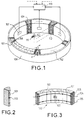
- the ring piezoelectric forming the transducer is achieved by assembling a set of elementary segments 101 having the form of prisms with trapezoidal section quite similar to those used in the prior art.
- the ring is divided into a set of substantially identical sectors 102 bringing together subsets of segments.
- the diameter of the ring is of the order of 20 cm and it is divided into 5 sectors comprising each 8 segments.
- FIG. 3 It is formed of 8 elementary segments 101 in piezoelectric ceramic, PZT for example. These segments are glued together with interposition electrodes 103 which allow the application of electrical voltages of excitement. According to a known technique, the segments are polarized tangentially alternately in opposite directions. The electrodes 103 are joined alternately to connections 104 and 105 which allow these electrical voltages to be applied to the electrodes.
- ends of the sector are provided with parts metal bonded to the outer faces of the end segments.
- These metal parts are wedge-shaped and their outer side faces make an angle ⁇ with the direction of the radius of the ring, as shown in FIG. 1. This angle ⁇ is such that the width of the corner is greater over the inner surface of the ring only on the outer surface thereof.
- strain gauge 107 there is also arranged on the inner face of the sector at least one strain gauge 107, which makes it possible to measure the constraints applied to the sectors at the level of this interior face.
- This strain gauge is for example produced in the known form of a film supporting metal electrodes arranged in such a way that the extension or contraction of the surface on which the gauge is stuck causes a variation in resistance of these electrodes according to a law known.
- All 5 sectors are arranged inside a ring conformator 108 and which makes it possible to define the shape and the dimensions of the piezoelectric ring.
- This ring is for example made of glass epoxy with a carefully polished interior surface.
- the dimensions of the sectors are provided so that there remains a clearance between the metal parts of the ends of two adjacent sectors. This clearance is filled by shims having the form of corners 109. These wedges, a copy of which is shown in FIG. 2, therefore come place themselves between the sectors and allow these sectors to be blocked at inside the shaping ring 108.
- the angle between the two faces lateral of these wedges is studied to correspond to the angle alpha of the end pieces of the sectors, so that when the wedges are in position these outer faces are applied to the faces exterior of these end pieces with such minimal angular play as possible, to avoid undue stress at the contact points between the wedges and the end pieces.
- the faces of the shims 109 oriented towards the inside of the ring are provided with tapped holes 110, here 3 in number, which can be used to receive clamping devices from screw into these holes by pressing on the faces of the end pieces 106 themselves oriented towards the inside of the ring.
- These pieces of tightening may be more or less complicated, but in the example of shown embodiment they are composed of screws 111 on which are threaded washers 112. These screws are screwed into the holes threaded, then on the washers, themselves supported on the parts 106. There is thus exerted on the wedges 109 an inward traction of the ring which tends, given the angles ⁇ , to spread the sectors 101 and to enlarge the ring formed by all of these sectors and wedges. Under this widening effect the piezoelectric ring presses firmly on the inside of the shaping ring 108, which, in a first, keep all parts in position.
- the invention proposes to use the strain gauges 107 described above. For this, they will be connected to measuring means 113 which allow to determine the stress at these gauges.
- the constraint where these gauges are placed indicates, at a coefficient near known multiplier, the global stress applied to ceramics forming each sector. The sectors are small enough that the stresses thus obtained and measured are uniformly distributed. In the case of a larger ring, we would eventually have to use a more sectors.
- the tightening of the screws will be done gradually by constantly checking the evolution of the constraints, so as to obtain the desired overall stress and to minimize maximum deviations between the stresses measured locally.
- the shaping ring 108 is of course involved in the acoustic characteristics of the transducer thus produced, as is moreover the case in the other prestressing systems already known. We have determined that to get correct results, especially don't not excessively disturbing the functioning of the ring piezoelectric, it was better to use a shaping ring whose dynamic stiffness is about ten times lower than that of the ring piezoelectric ceramic.
- this device is particularly easy to implement and therefore inexpensive.
- it is modular, which makes it possible, if necessary, to replace only one segment in case of damage to it. Constraints are distributed in a remarkably uniform manner, and their variations over the time is very low. We can completely adjust this preload, either by depending on operational conditions, either to correct the drift in the time.
- the assembly is removable, which allows the repairs cited above.
- the metal parts 106 and 109 if necessary, promote thermal drainage, especially when the ring is requested by very high electrical powers.
Description
- la figure 1, une vue en perspective cavalière d'un transducteur en anneau selon l'invention;
- la figure 2, une vue en perspective cavalière d'un coin de réglage de cet anneau; et
- la figure 3, une vue en perspective cavalière d'un secteur de l'anneau compris entre deux coins tels que ceux de la figure 2.
Claims (6)
- Transducteur acoustique en anneau précontraint, du type comprenant un ensemble de segments piézoélectriques (101) disposés en forme d'anneau, groupés pour former des secteurs (102) sensiblement identiques séparés par des cales (109) en forme de coin, caractérisé en ce qu'il comprend en outre des pièces d'extrémité (106) fixées aux extrémités de ces secteurs pour délimiter entre eux des intervalles en forme de coin dont l'extrémité la plus étroite est dirigée vers l'intérieur de l'anneau, des cales de serrage (109) en forme de coin adaptés à ces intervalles et placées dans ceux-ci, un anneau conformateur (108) permettant de maintenir l'ensemble des secteurs, et des moyens de serrage (110-112) permettant de faire glisser les cales de serrage vers l'intérieur de l'anneau pour précontraindre les segments par l'anneau conformateur.
- Transducteur selon la revendication 1, caractérisé en ce qu'il comprend en outre des jauges de contrainte (107) fixées sur la face intérieure des secteurs pour permettre de mesurer les contraintes tangentielles appliquées aux segments.
- Transducteur selon l'une quelconque des revendications 1 et 2, caractérisé en ce que les moyens de serrage sont formés de vis (111) fixées dans des trous ménagés dans la face interne des cales de serrage (109) et munies de rondelles (112) venant s'appuyer sur les pièces d'extrémité (106) des secteurs pour permettre d'exercer une traction sur les cales lorsqu'on visse les vis.
- Transducteur selon l'une quelconque des revendications 1 à 3, caractérisé en ce que les intervalles subsistant d'une part entre les cales de serrage (109) et l'anneau conformateur (108) et d'autre part entre ces mêmes cales de serrage et les moyens de serrage (110-112) sont bouchés avec un produit de remplissage lorsque le réglage est obtenu.
- Transducteur selon l'une quelconque des revendications 1 à 4, caractérisé en ce que la raideur dynamique de l'anneau conformateur (208) est sensiblement dix fois plus faible que celle des segments piézoélectriques (101).
- Procédé de réglage d'un transducteur selon l'une quelconque des revendications 2 à 5, caractérisé en ce que l'on serre progressivement les moyens de serrage (110-112) en surveillant les indications données par les jauges de contrainte (107) pour obtenir sur chaque secteur des contraintes identiques et égales à la valeur souhaitée.
Applications Claiming Priority (3)
| Application Number | Priority Date | Filing Date | Title |
|---|---|---|---|
| FR9415587 | 1994-12-23 | ||
| FR9415587A FR2728755B1 (fr) | 1994-12-23 | 1994-12-23 | Transducteur acoustique en anneau precontraint |
| PCT/FR1995/001676 WO1996020046A1 (fr) | 1994-12-23 | 1995-12-15 | Transducteur acoustique en anneau precontraint |
Publications (2)
| Publication Number | Publication Date |
|---|---|
| EP0799097A1 EP0799097A1 (fr) | 1997-10-08 |
| EP0799097B1 true EP0799097B1 (fr) | 1998-09-23 |
Family
ID=9470196
Family Applications (1)
| Application Number | Title | Priority Date | Filing Date |
|---|---|---|---|
| EP95942751A Expired - Lifetime EP0799097B1 (fr) | 1994-12-23 | 1995-12-15 | Transducteur acoustique en anneau precontraint |
Country Status (7)
| Country | Link |
|---|---|
| US (1) | US6065349A (fr) |
| EP (1) | EP0799097B1 (fr) |
| JP (1) | JP3653733B2 (fr) |
| AU (1) | AU695815B2 (fr) |
| DE (1) | DE69505014T2 (fr) |
| FR (1) | FR2728755B1 (fr) |
| WO (1) | WO1996020046A1 (fr) |
Families Citing this family (6)
| Publication number | Priority date | Publication date | Assignee | Title |
|---|---|---|---|---|
| FR2776161B1 (fr) * | 1998-03-10 | 2000-05-26 | Thomson Marconi Sonar Sas | Antenne d'emission acoustique annulaire demontable |
| FR2826828B1 (fr) * | 2001-06-29 | 2003-12-12 | Thomson Marconi Sonar Sas | Transducteur acoustique a anneau precontraint |
| US7500398B2 (en) * | 2003-01-17 | 2009-03-10 | Kistler Holding, Ag | Prestressing element for sensors |
| US8854923B1 (en) * | 2011-09-23 | 2014-10-07 | The United States Of America As Represented By The Secretary Of The Navy | Variable resonance acoustic transducer |
| FR3015785B1 (fr) * | 2013-12-20 | 2015-12-25 | Thales Sa | Antenne omnidirectionnelle compacte pour sonar trempe |
| CN109633614B (zh) * | 2018-11-29 | 2023-08-01 | 哈尔滨工程大学 | 一种低后辐射高频换能器线阵 |
Family Cites Families (6)
| Publication number | Priority date | Publication date | Assignee | Title |
|---|---|---|---|---|
| US3043967A (en) * | 1960-01-13 | 1962-07-10 | Walter L Clearwaters | Electrostrictive transducer |
| US3230505A (en) * | 1963-06-27 | 1966-01-18 | David E Parker | Reinforced ceramic cylindrical transducers |
| US4313510A (en) * | 1980-11-24 | 1982-02-02 | General Electric Company | Weighing scale with dynamic zero error correction |
| US4546459A (en) * | 1982-12-02 | 1985-10-08 | Magnavox Government And Industrial Electronics Company | Method and apparatus for a phased array transducer |
| DE3542741A1 (de) * | 1985-12-03 | 1987-06-04 | Taga Electric Co Ltd | Torsionsschwingungseinrichtung |
| GB9409133D0 (en) * | 1994-05-09 | 1994-11-30 | Secr Defence | Sonar ring transducer |
-
1994
- 1994-12-23 FR FR9415587A patent/FR2728755B1/fr not_active Expired - Lifetime
-
1995
- 1995-12-15 EP EP95942751A patent/EP0799097B1/fr not_active Expired - Lifetime
- 1995-12-15 AU AU43934/96A patent/AU695815B2/en not_active Expired
- 1995-12-15 WO PCT/FR1995/001676 patent/WO1996020046A1/fr active IP Right Grant
- 1995-12-15 DE DE69505014T patent/DE69505014T2/de not_active Expired - Lifetime
- 1995-12-15 JP JP52024096A patent/JP3653733B2/ja not_active Expired - Fee Related
- 1995-12-15 US US08/860,223 patent/US6065349A/en not_active Expired - Lifetime
Also Published As
| Publication number | Publication date |
|---|---|
| FR2728755B1 (fr) | 1997-01-24 |
| AU4393496A (en) | 1996-07-19 |
| JPH10511523A (ja) | 1998-11-04 |
| JP3653733B2 (ja) | 2005-06-02 |
| FR2728755A1 (fr) | 1996-06-28 |
| WO1996020046A1 (fr) | 1996-07-04 |
| DE69505014D1 (de) | 1998-10-29 |
| AU695815B2 (en) | 1998-08-20 |
| US6065349A (en) | 2000-05-23 |
| DE69505014T2 (de) | 1999-05-06 |
| EP0799097A1 (fr) | 1997-10-08 |
Similar Documents
| Publication | Publication Date | Title |
|---|---|---|
| EP0005409B1 (fr) | Transducteurs piézoélectriques à amplification mécanique pour très basses fréquences et antennes acoustiques | |
| FR2531533A1 (fr) | Capteur piezo-electrique de pression et/ou de temperature | |
| EP1056985B1 (fr) | Capteur d'extensiometrie destine a mesurer des deformations a calage mecanique de premiere pose et calibrage automatique en fonction de ce calage | |
| FR2533851A1 (fr) | Support de piece et procede de montage d'une piece sur un tel support | |
| EP0506554B1 (fr) | Capteur de pression résonant | |
| FR2668836A1 (fr) | Transducteur acoustique de puits. | |
| EP0462037B1 (fr) | Transducteur électro-acoustique immergé | |
| EP0799097B1 (fr) | Transducteur acoustique en anneau precontraint | |
| FR2893407A1 (fr) | Etalon de calibrage. | |
| FR2498316A1 (fr) | Moteur piezo-electrique pour gyroscopes a anneaux laser | |
| EP0404673B1 (fr) | Capteur à membrane à concentration de déformations | |
| FR3084167A1 (fr) | Accelerometre a detection par jauge de contraintes a precision amelioree | |
| CA2885523A1 (fr) | Capteur de pression a base de nanojauges couplees a un resonateur | |
| EP3491371B1 (fr) | Résonateur mécanique optimisé pour fonctionner dans un fluide | |
| EP1423665B1 (fr) | Appareil de pesage | |
| FR2655803A1 (fr) | Procedes pour augmenter la puissance des transducteurs electro-acoustiques a basse frequence et transducteurs correspondants. | |
| WO2004007127A2 (fr) | Dispositif de fixation d'une fibre rigide et fragile comprenant une gaine mecaniquement deformable et susceptible d'etre soumise a au moins une contrainte mecanique | |
| FR2776065A1 (fr) | Capteur de force resonnant a elements piezo-electriques | |
| FR2500623A1 (fr) | Debitmetre a vortex a detection exterieure | |
| FR2605736A1 (fr) | Poutrelle de jauge de contrainte avec protection contre les surcharges incorporee | |
| EP1062055B1 (fr) | Antenne d'emission acoustique annulaire demontable | |
| EP4058777A1 (fr) | Banc de caracterisation mecanique d'objets minces | |
| EP4078710A1 (fr) | Banc de caracterisation mecanique d'objets minces a fiabilite augmentee | |
| FR2628205A1 (fr) | Jauge de pression a fibre optique | |
| FR2720509A1 (fr) | Microaccéléromètre à résonateur compensé en température. |
Legal Events
| Date | Code | Title | Description |
|---|---|---|---|
| PUAI | Public reference made under article 153(3) epc to a published international application that has entered the european phase |
Free format text: ORIGINAL CODE: 0009012 |
|
| 17P | Request for examination filed |
Effective date: 19970612 |
|
| AK | Designated contracting states |
Kind code of ref document: A1 Designated state(s): DE GB IT |
|
| GRAG | Despatch of communication of intention to grant |
Free format text: ORIGINAL CODE: EPIDOS AGRA |
|
| 17Q | First examination report despatched |
Effective date: 19980202 |
|
| GRAG | Despatch of communication of intention to grant |
Free format text: ORIGINAL CODE: EPIDOS AGRA |
|
| GRAH | Despatch of communication of intention to grant a patent |
Free format text: ORIGINAL CODE: EPIDOS IGRA |
|
| GRAH | Despatch of communication of intention to grant a patent |
Free format text: ORIGINAL CODE: EPIDOS IGRA |
|
| GRAA | (expected) grant |
Free format text: ORIGINAL CODE: 0009210 |
|
| AK | Designated contracting states |
Kind code of ref document: B1 Designated state(s): DE GB IT |
|
| REF | Corresponds to: |
Ref document number: 69505014 Country of ref document: DE Date of ref document: 19981029 |
|
| GBT | Gb: translation of ep patent filed (gb section 77(6)(a)/1977) |
Effective date: 19981112 |
|
| PLBE | No opposition filed within time limit |
Free format text: ORIGINAL CODE: 0009261 |
|
| STAA | Information on the status of an ep patent application or granted ep patent |
Free format text: STATUS: NO OPPOSITION FILED WITHIN TIME LIMIT |
|
| 26N | No opposition filed | ||
| REG | Reference to a national code |
Ref country code: GB Ref legal event code: IF02 |
|
| PGFP | Annual fee paid to national office [announced via postgrant information from national office to epo] |
Ref country code: DE Payment date: 20141209 Year of fee payment: 20 Ref country code: GB Payment date: 20141210 Year of fee payment: 20 |
|
| PGFP | Annual fee paid to national office [announced via postgrant information from national office to epo] |
Ref country code: IT Payment date: 20141128 Year of fee payment: 20 |
|
| REG | Reference to a national code |
Ref country code: DE Ref legal event code: R071 Ref document number: 69505014 Country of ref document: DE |
|
| REG | Reference to a national code |
Ref country code: GB Ref legal event code: PE20 Expiry date: 20151214 |
|
| PG25 | Lapsed in a contracting state [announced via postgrant information from national office to epo] |
Ref country code: GB Free format text: LAPSE BECAUSE OF EXPIRATION OF PROTECTION Effective date: 20151214 |