EP0798427A2 - Connecting system for construction elements, in particular for fixing roof accessories to inclined and flat roofs - Google Patents
Connecting system for construction elements, in particular for fixing roof accessories to inclined and flat roofs Download PDFInfo
- Publication number
- EP0798427A2 EP0798427A2 EP97104691A EP97104691A EP0798427A2 EP 0798427 A2 EP0798427 A2 EP 0798427A2 EP 97104691 A EP97104691 A EP 97104691A EP 97104691 A EP97104691 A EP 97104691A EP 0798427 A2 EP0798427 A2 EP 0798427A2
- Authority
- EP
- European Patent Office
- Prior art keywords
- spacers
- fastening
- formations
- plates
- plate
- Prior art date
- Legal status (The legal status is an assumption and is not a legal conclusion. Google has not performed a legal analysis and makes no representation as to the accuracy of the status listed.)
- Withdrawn
Links
- 238000010276 construction Methods 0.000 title description 2
- 125000006850 spacer group Chemical group 0.000 claims abstract description 60
- 230000015572 biosynthetic process Effects 0.000 claims abstract description 34
- 238000005755 formation reaction Methods 0.000 claims abstract description 34
- 239000000463 material Substances 0.000 claims description 3
- 239000002184 metal Substances 0.000 claims 1
- 238000009413 insulation Methods 0.000 description 12
- 238000009434 installation Methods 0.000 description 4
- 238000009415 formwork Methods 0.000 description 3
- 239000002023 wood Substances 0.000 description 3
- 238000009423 ventilation Methods 0.000 description 2
- 101100498160 Mus musculus Dach1 gene Proteins 0.000 description 1
- 229910000831 Steel Inorganic materials 0.000 description 1
- 238000005452 bending Methods 0.000 description 1
- 150000001875 compounds Chemical class 0.000 description 1
- 238000011161 development Methods 0.000 description 1
- 230000018109 developmental process Effects 0.000 description 1
- 230000000284 resting effect Effects 0.000 description 1
- 239000010959 steel Substances 0.000 description 1
Images
Classifications
-
- E—FIXED CONSTRUCTIONS
- E04—BUILDING
- E04D—ROOF COVERINGS; SKY-LIGHTS; GUTTERS; ROOF-WORKING TOOLS
- E04D13/00—Special arrangements or devices in connection with roof coverings; Protection against birds; Roof drainage ; Sky-lights
- E04D13/10—Snow traps ; Removing snow from roofs; Snow melters
-
- E—FIXED CONSTRUCTIONS
- E04—BUILDING
- E04D—ROOF COVERINGS; SKY-LIGHTS; GUTTERS; ROOF-WORKING TOOLS
- E04D13/00—Special arrangements or devices in connection with roof coverings; Protection against birds; Roof drainage ; Sky-lights
- E04D13/12—Devices or arrangements allowing walking on the roof or in the gutter
Definitions
- the invention relates to a fastening system for components of different types, which are to be attached to or on a support element by bridging a non-or limited load-bearing material layer, a space or the like, in particular for fastening roof accessories on sloping roofs and flat roofs that are insulated and / or ventilated , and for fastening components to insulated and / or ventilated building facades.
- the attachment of the holder on a roof is relatively complex, since first the corresponding height of the holder must be set with at least one adjusting screw and then the holder by means of Wood screws or nails, which are inserted through appropriate holes in the support leg of the foot part of the holder, for example an angular profile, must be screwed or nailed to the rafters or the boards of the formwork of the roof.
- Another disadvantage of the known holder is that they form thermal bridges that cause heat loss.
- the invention has for its object to develop a fastening system for components of different types, in particular for attaching roof accessories on pitched roofs and flat roofs with insulation and / or ventilation and for attaching components to insulated and / or ventilated building facades, which is simple Installation of the holder used for the various components and a wide range of applications.
- the subclaims contain advantageous and expedient developments of the spacers of the fastening system.
- the spacers of the fastening system enable simple and quick installation of components of different types by bridging a non-or limited load-bearing material layer or an intermediate space on a support element, in particular roof accessories on sloping roofs and flat roofs with insulation and / or ventilation and components insulated and / or ventilated building facades.
- the special construction of the spacers of the fastening system prevents the formation of thermal bridges.
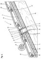
- the fastening system which, as shown in Figure 4, preferably for attaching roof accessories, e.g. of snow guard 2 for a log 22, used on a sloping, ventilated roof 1 with thermal insulation 3, consists of spacers of different designs.
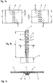
- the spacer 4 shown in FIGS. 1a to 1c is formed by two setting plates 5, 6 made of sheet steel or plastic, one of which has 5 form-like shapes 7, which are designed as circular, narrow webs and in a row 8 with a specific pitch t over the height h of the plate 5 are arranged in the middle thereof.
- the other setting plate 6 has a row 9, which extends over its height h in the middle of the plate and has the formations 7 of the first setting plate 5, the division t of which corresponds to the division of the formations 7.
- the desired height H or length of the spacer 4 can be set in stages.
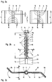
- the spacer 14 according to Figures 2a to 2c consists of two setting plates 5, 6, each having oppositely directed, identically shaped formations 7, 15, which are designed as circular, narrow webs, in a row 8 with a certain pitch t over the Height h of the plates 5, 6 are each separated from one another by openings 16 with the dimensions corresponding to the formations 7, 15.
- the setting plates 5, 6 of the spacer 14 can be assembled in the same way as in the case of the spacer 4 described above with reference to FIGS. 1a to 1c in different positions for setting the desired height H or length of the spacer 14 and by means of a fastening screw 11 on or on be attached to a support element 13, wherein the screw 11 for fastening the spacer 14 on the support element 13 can be used simultaneously for fastening a component to the spacer 14.
- the formations 7 and 15 of one plate engage in the openings 16 of the other plate, such that the formations 7, 15 form a through opening 12 for a fastening screw 11 or a screw bolt with a fastening nut.
- the plate edges 5a, 5b; pointing in the adjustment direction of the two setting plates 5, 6 of the spacer 14; 6a 6b are folded in opposite directions. Because of this profile shape are the assembled plates 5, 6 in a line or strip shape against each other, so that the formation of thermal bridges is avoided.
- An impact tip 20 which on the contact edge 5c of the on a support member 13 made of wood, e.g. a lower ratchet plate 5 standing on a rafters is formed, serves as an anti-rotation device for the spacers 14.
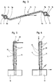
- the spacer 21 has two adjusting plates 5, 6 designed as grid plates, each with two rows of formations 7, 15 and openings 16, which on or in the folded plate edges 5a, 5b; 6a, 6b are arranged.
- the spacer 21 is adjustable in the height direction z of a right-angled coordinate system and can be extended in the x-direction of the coordinate system, and the two setting plates 5, 6 of the spacer 21 are provided with two Fastening screws 11 on a support element, such as a rafters, attached.
- FIG. 4 shows the installation of snow guard supports 2 with a round timber 22 in a roof 1 covered with flat roof tiles 23 and insulated on the outside by means of the spacers 21 according to FIG. 3.
- the insulation 3 fastened with counter battens 24 to the rafters 25 and the counter battens 24 the location provided for fastening the snow guard support 2 is cut out in accordance with the profile of the spacer 21.
- the height H of the spacer 21 is adjusted to the thickness of the insulation 3, the counter batten 24 and the roof batten 30 by appropriate assembly of the two setting plates 5, 6, the support leg 26 of the snow guard support 2, which has fastening holes 27, is placed on the spacer 21, and the two setting plates 5, 6 of the spacer 21 are together with the snow guard support 2 by means of the fastening screws 11, which are designed as wood screws, through the fastening holes 27 of the support leg 26 of the snow guard support 2 and the through openings 12 formed by the formations 7, 15 of the setting plates 5, 6 be plugged, locked firmly against each other.
- the fastening screws 11 are screwed into the rafters 25, so that the snow guard support 2 is fixedly attached to the substructure of the roof 1 by means of the spacer 21. Possibly. the insulation 3 is still sealed with a plastic compound in the area of the cut-out for the spacer 21.
- the fastening screws 11 of the spacers 14 are stabilized due to the guidance of the screw shaft 18 by the adjusting plates 5, 6 in such a way that failure of the screws 11 due to bending and shear forces P caused by snow loads acting in the roof pitch direction is excluded.
- Figure 5 shows a height and length adjustable spacer 28 with a Z-profile.
- FIG. 6 shows a spacer 29 with an inverted T-profile, which can be adjusted in the height direction z of a right-angled coordinate system and can be extended in the x and y directions of the coordinate system.
Landscapes
- Engineering & Computer Science (AREA)
- Architecture (AREA)
- Civil Engineering (AREA)
- Structural Engineering (AREA)
- Buildings Adapted To Withstand Abnormal External Influences (AREA)
- Roof Covering Using Slabs Or Stiff Sheets (AREA)
Abstract
Description
Die Erfindung betrifft ein Befestigungssystem für Bauteile unterschiedlicher Art, die unter Überbrückung einer nicht oder begrenzt tragfähigen Materialschicht, eines Zwischenraumes oder dergleichen an oder auf einem Tragelement anzubringen sind, insbesondere zur Befestigung von Dachzubehörteilen auf geneigten Dächern und Flachdächern, die gedämmt und/oder belüftet sind, und zur Befestigung von Bauteilen an gedämmten und/oder belüfteten Gebäudefassaden.The invention relates to a fastening system for components of different types, which are to be attached to or on a support element by bridging a non-or limited load-bearing material layer, a space or the like, in particular for fastening roof accessories on sloping roofs and flat roofs that are insulated and / or ventilated , and for fastening components to insulated and / or ventilated building facades.
Die Befestigung von Dachzubehörteilen wie Steigtritten, Laufrosten, Schneefanggittern und dergleichen auf der Dämmung eines geneigten Daches, die auf der Schalung des Daches oder den Dachsparren angebracht ist, erfordert die Verlegung von Festpunkten aus der Ebene der Dachsparren bzw. der Schalung des Daches über die Dämmung. Dies erreicht man mit höhenverstellbaren Haltern, die aus einem Fußteil und einem an diesem mittels Schrauben verstellbar befestigten Kopfteil bestehen. Nach der Befestigung der entsprechend der Stärke der Dämmschicht des Daches eingestellten Halter mit dem Fußteil auf den Dachsparren können am Kopfteil der Halter Dachzubehörteile angebracht werden. Die Halter können vor oder nach der Anbringung der Dämmplatten oder Dämmbahnen auf den Dachsparren befestigt werden, wobei im zweiten Fall die Dämmung an den Stellen des Daches, an denen Halter angebracht werden sollen, entsprechend ausgespart werden muß.Fastening roof accessories such as risers, gratings, snow guards and the like on the insulation of an inclined roof, which is attached to the formwork of the roof or the rafters, requires the laying of fixed points from the level of the rafters or the formwork of the roof over the insulation . This is achieved with height-adjustable brackets, which consist of a foot section and a head section that is attached to it by screws. After attaching the brackets to the rafters, which are adjusted according to the thickness of the insulation layer of the roof, roof accessories can be attached to the head section of the brackets. The brackets can be attached to the rafters before or after the installation of the insulation boards or insulation sheets, in the second case the insulation at the locations on the roof where brackets are to be attached must be cut out accordingly.
Die Anbringung der Halter auf einem Dach ist verhältnismäßig aufwendig, da zunächst die entsprechende Höhe der Halter mit mindestens einer Stellschraube eingestellt werden muß und danach die Halter mittels Holzschrauben oder Nägeln, die durch entsprechende Löcher in dem Aufstandsschenkel des zum Beispiel als Winkelprofil ausgebildeten Fußteils der Halter gesteckt werden, auf den Dachsparren bzw. den Brettern der Schalung des Daches festgeschraubt oder gestgenagelt werden müssen.The attachment of the holder on a roof is relatively complex, since first the corresponding height of the holder must be set with at least one adjusting screw and then the holder by means of Wood screws or nails, which are inserted through appropriate holes in the support leg of the foot part of the holder, for example an angular profile, must be screwed or nailed to the rafters or the boards of the formwork of the roof.
Ein weiterer Nachteil der bekannten Halter besteht darin, daß diese Wärmebrücken bilden, die Wärmeverluste bewirken.Another disadvantage of the known holder is that they form thermal bridges that cause heat loss.
Der Erfindung liegt die Aufgabe zugrunde, ein Befestigungssystem für Bauteile unterschiedlicher Art, insbesondere zur Befestigung von Dachzubehörteilen auf geneigten Dächern und Flachdächern mit Dämmung und/oder Belüftung und zur Befestigung von Bauteilen an gedämmten und/oder belüfteten Gebäudefassaden zu entwickeln, das sich durch eine einfache Montage der verwendeten Halter für die verschiedenen Bauteile und eine große Anwendungsbreite auszeichnet.The invention has for its object to develop a fastening system for components of different types, in particular for attaching roof accessories on pitched roofs and flat roofs with insulation and / or ventilation and for attaching components to insulated and / or ventilated building facades, which is simple Installation of the holder used for the various components and a wide range of applications.
Diese Aufgabe ist erfindungsgemäß gelöst durch ein Befestigungssystem, das aus Abstandshaltern gemäß den Patentansprüchen 1 und 2 besteht.This object is achieved according to the invention by a fastening system which consists of spacers according to patent claims 1 and 2.
Die Unteransprüche beinhalten vorteilhafte und zweckmäßige Weiterbildungen der Abstandshalter des Befestigungssystems.The subclaims contain advantageous and expedient developments of the spacers of the fastening system.
Die Abstandshalter des erfindungsgemäßen Befestigungssystems ermöglichen eine einfache und schnelle Montage von Bauteilen unterschiedlicher Art unter Überbrückung einer nicht oder begrenzt tragfähigen Materialschicht oder eines Zwischenraumes auf einem Tragelement, insbesondere von Dachzubehörteilen auf geneigten Dächern und Flachdächern mit einer Dämmung und/oder einer Belüftung sowie von Bauteilen an gedämmten und/oder belüfteten Gebäudefassaden. Die besondere Konstruktion der Abstandshalter des Befestigungssystems vermeidet die Bildung von Wärmebrücken.The spacers of the fastening system according to the invention enable simple and quick installation of components of different types by bridging a non-or limited load-bearing material layer or an intermediate space on a support element, in particular roof accessories on sloping roofs and flat roofs with insulation and / or ventilation and components insulated and / or ventilated building facades. The special construction of the spacers of the fastening system prevents the formation of thermal bridges.
Das erfindungsgemäße Befestigungssystem ist nachfolgend anhand verschiedener Ausführungsbeispiele von Abstandshaltern erläutert, die in schematischen Zeichnungsfiguren dargestellt sind, die im einzelnen folgendes zeigen:
- Figur 1a
- Ansichten der beiden Stellplatten einer ersten Ausführungsform eines Abstandshalters,
- Figur 1b
- den auf einem Tragelement befestigten Abstandshalter mit den Stellplatten nach Figur 1a in der Seitenansicht,
- Figur 1c
- einen um 90° gedrehten Querschnitt des Abstandshalters nach Linie Ic-Ic der Figur 1b,
- Figur 2a
- Ansichten der beiden Stellplatten einer zweiten Ausführungsform eines Abstandshalters,
- Figur 2b
- den auf einem Tragelement angebrachten Abstandshalter mit den Stellplatten nach Figur 2a im Schnitt nach Linie IIb-IIb der Figur 2c,
- Figur 2c
- einen um 90° gedrehten Querschnitt des Abstandshalters nach Linie IIc-IIc der Figur 2b,
- Fig. 3
- eine Draufsicht einer dritten Ausführungsform des Abstandhalters,
- Figur 4
- einen in Dachneigungsrichtung verlaufenden Schnitt durch ein mit flachen Dachsteinen gedecktes Dach mit einer mit einem Abstandhalter nach den Figuren 2a bis 2c auf einem Dachsparren befestigten Schneefangstütze für ein Rundholz und
- die
Figuren 5 und 6 - Seitenansichten von zwei weiteren Ausführungsformen des Abstandshalters des Befestigungssystems.
- Figure 1a
- Views of the two setting plates of a first embodiment of a spacer,
- Figure 1b
- the spacer attached to a support element with the setting plates according to Figure 1a in side view,
- Figure 1c
- 2 shows a cross section of the spacer rotated by 90 ° according to line Ic-Ic in FIG.
- Figure 2a
- Views of the two setting plates of a second embodiment of a spacer,
- Figure 2b
- the spacer attached to a support element with the setting plates according to FIG. 2a in section along line IIb-IIb of FIG. 2c,
- Figure 2c
- 3 shows a cross section of the spacer rotated by 90 ° according to line IIc-IIc of FIG. 2b,
- Fig. 3
- a plan view of a third embodiment of the spacer,
- Figure 4
- a section running in the roof pitch direction through a roof covered with flat roof tiles with a snow guard for a log and attached with a spacer according to Figures 2a to 2c on a rafters
- Figures 5 and 6
- Side views of two further embodiments of the spacer of the fastening system.
Das Befestigungssystem, das entsprechend der Darstellung in Figur 4 bevorzugt zur Anbringung von Dachzubehörteilen, z.B. von Schneefangstützen 2 für ein Rundholz 22, auf einem schrägen, belüfteten Dach 1 mit einer Wärmedämmung 3 verwendet wird, besteht aus Abstandshaltern unterschiedlicher Ausführung.The fastening system, which, as shown in Figure 4, preferably for attaching roof accessories, e.g. of snow guard 2 for a
Der in den Figuren 1a bis 1c dargestellte Abstandshalter 4 wird durch zwei aus Stahlblech oder Kunststoff hergestellte Stellplatten 5, 6 gebildet, deren eine 5 formgleiche Ausformungen 7 aufweist, die als kreisförmige, schmale Stege ausgebildet sind und in einer Reihe 8 mit einer bestimmten Teilung t über die Höhe h der Platte 5 in der Mitte derselben angeordnet sind.The spacer 4 shown in FIGS. 1a to 1c is formed by two setting
Die andere Stellplatte 6 weist eine über ihre Höhe h in der Plattenmitte verlaufende Reihe 9 mit den Ausformungen 7 der ersten Stellplatte 5 angepaßten Öffnungen 10 auf, deren Teilung t der Teilung der Ausformungen 7 entspricht.The
Durch Zusammensetzen der beiden Stellplatten 5, 6 in unterschiedlichen Schiebestellungen, in denen die Ausformungen 7 der einen Stellplatte 5 durch die Öffnungen 10 der anderen Stellplatte 6 gesteckt werden, kann die gewünschte Höhe H bzw. Länge des Abstandshalters 4 stufenweise eingestellt werden.By assembling the two
Eine Befestigungsschraube 11, die durch die zwischen den Ausformungen 7 der einen Stellplatte 5 und der anderen flachen Stellplatte 6 gebildete Durchgangsöffnung 12 durchgesteckt und in ein Tragelement 13, z.B. einen Dachsparren eines geneigten Daches eingeschraubt wird, dient zur Verriegelung und gegenseitigen Verspannung der beiden Stellplatten 5, 6 in der jeweiligen Höheneinstellung H des Abstandshalters 4 und zur Befestigung eines Bauteils auf dem Tragelement 13, z.B. einer Laufroststütze auf dem Dachsparren des Daches.A
Der Abstandshalter 14 nach den Figuren 2a bis 2c besteht aus zwei Stellplatten 5, 6, die jeweils entgegengesetzt gerichtete, gleich ausgebildete Ausformungen 7, 15 aufweisen, die als kreisförmige, schmale Stege ausgebildet sind, in einer Reihe 8 mit einer bestimmten Teilung t über die Höhe h der Platten 5, 6 jeweils durch Öffnungen 16 mit den den Ausformungen 7, 15 entsprechenden Abmessungen voneinander getrennt sind.The
Die Stellplatten 5, 6 des Abstandshalters 14 können in gleicher Weise wie bei dem vorstehend anhand der Figuren 1a bis 1c beschriebenen Abstandshalter 4 in unterschiedlichen Stellungen zur Einstellung der gewünschten Höhe H bzw. Länge des Abstandshalters 14 zusammengesetzt und mittels einer Befestigungsschraube 11 auf bzw. an einem Tragelement 13 angebracht werden, wobei die Schraube 11 zur Befestigung des Abstandshalters 14 auf dem Tragelement 13 gleichzeitig zur Befestigung eines Bauteils am Abstandshalter 14 verwendet werden kann. Beim Zusammenfügen der beiden Stellplatten 5, 6 greifen die Ausformungen 7 bzw. 15 der einen Platte in die Öffnungen 16 der anderen Platte, derart, daß die Ausformungen 7, 15 eine Durchgangsöffnung 12 für eine Befestigungsschraube 11 oder einen Schraubenbolzen mit einer Befestigungsmutter bilden.The
Die in Verstellrichtung der beiden Stellplatten 5, 6 des Abstandshalters 14 weisenden Plattenränder 5a, 5b; 6a 6b sind entgegengesetzt abgekantet. Aufgrund dieser Profilform liegen die zusammengesetzten Stellplatten 5, 6 linien- bzw. streifenförmig gegeneinander, so daß eine Ausbildung von Wärmebrücken vermieden wird.The plate edges 5a, 5b; pointing in the adjustment direction of the two
Bei den Abstandshaltern 14, deren Stellplatten 5, 6 entgegengesetzt gerichtete Ausformungen 7, 15 besitzen, weist die auf dem Tragelement 13, z.B. einem Dachsparren stehende bzw. die an dem Tragelement anliegende Stellplatte 5 an der Aufstandskante 5c eine zu den anderen Ausformungen 7 entgegengerichtete Ausformungen 7a zur Führung der Befestigungsschraube 11 auf, und die obere bzw. äußere Stellplatte 6 besitzt an der Oberkante bzw. Außenkante 6c eine zu den anderen Ausformungen 15 entgegengerichtete Ausformung 15a zur Abstützung des Kopfes 17 der Befestigungsschraube 11 oder einer auf einem Schraubenbolzen aufgeschraubten Befestigungsmutter.In the case of the
Eine auf dem Schaft 18 der Befestigungsschraube 11 sitzende Unterlegscheibe 19, die mittels einer Abkantung 19a gegen Verdrehen und Verkanten gesichert ist, dient zur Abstützung des Kopfes 17 der angezogenen Befestigungsschraube 11 oder eines Bauteils, z.B. einer Schneefangstütze 2 (Figur 4).A
Eine Einschlagspitze 20, die an der Aufstandskante 5c der auf einem Tragelement 13 aus Holz, z.B. einem Dachsparren stehenden unteren Stellplatte 5 angeformt ist, dient als Verdrehsicherung der Abstandshalter 14.An
Der Abstandshalter 21 nach Figur 3 weist zwei als Rasterplatten ausgebildete Stellplatten 5, 6 mit je zwei Reihen von Ausformungen 7, 15 und Öffnungen 16 auf, die an bzw. in den abgekanteten Plattenrändern 5a, 5b; 6a, 6b angeordnet sind. Der Abstandshalter 21 ist in Höhenrichtung z eines rechtwinkligen Koordinatensystems verstellbar und in x-Richtung des Koordinatensystems verlängerbar, und die beiden Stellplatten 5, 6 des Abstandshalters 21 werden mit zwei Befestigungsschrauben 11 auf einem Tragelement, z.B. einem Dachsparren, befestigt.The
Figur 4 zeigt den Einbau von Schneefangstützen 2 mit einem Rundholz 22 in ein mit flachen Dachsteinen 23 gedecktes, außen gedämmtes Dach 1 mittels der Abstandshalter 21 nach Figur 3. Zunächst werden die mit Konterlatten 24 auf den Dachsparren 25 befestigte Dämmung 3 und die Konterlatte 24 an der zur Befestigung der Schneefangstütze 2 vorgesehenen Stelle entsprechend dem Profil des Abstandshalters 21 ausgespart. Anschließend wird die Höhe H des Abstandshalters 21 durch entsprechendes Zusammensetzen der beiden Stellplatten 5, 6 auf die Stärke der Dämmung 3, der Konterlatte 24 und der Dachlatten 30 eingestellt, der Befestigungslöcher 27 aufweisende Auflageschenkel 26 der Schneefangstütze 2 wird auf den Abstandshalter 21 aufgesetzt, und die beiden Stellplatten 5, 6 des Abstandshalters 21 werden zusammen mit der Schneefangstütze 2 mittels der als Holzschrauben ausgebildeten Befestigungsschrauben 11, die durch die Befestigungslöcher 27 des Auflageschenkels 26 der Schneefangstütze 2 und die durch die Ausformungen 7, 15 der Stellplatten 5, 6 gebildeten Durchgangsöffnungen 12 gesteckt werden, fest gegeneinander verriegelt. Abschließend werden die Befestigungsschrauben 11 in den Dachsparren 25 eingeschraubt, so daß die Schneefangstütze 2 mittels des Abstandshalters 21 fest auf der Unterkonstruktion des Daches 1 angebracht ist. Ggf. wird die Dämmung 3 im Bereich der Aussparung für den Abstandshalter 21 noch mit einer Kunststoffmasse abgedichtet.FIG. 4 shows the installation of snow guard supports 2 with a
Die Befestigungsschrauben 11 der Abstandshalter 14 werden aufgrund der Führung des Schraubenschaftes 18 durch die Stellplatten 5, 6 derart stabilisiert, daß ein Versagen der Schrauben 11 aufgrund von in Dachneigungsrichtung auf diese wirkende, durch Schneelasten ausgelöste Biege- und Scherkräfte P ausgeschlossen ist.The fastening screws 11 of the
Figur 5 zeigt einen höhen- und längenverstellbaren Abstandshalter 28 mit einem Z-Profil.Figure 5 shows a height and length
Schließlich ist Figur 6 ein Abstandshalter 29 mit einer umgekehrten T-Profil zu entnehmen, der in Höhenrichtung z eines rechtwinkligen Koordinatensystems einstellbar sowie in x- und y-Richtung des Koordinatensystems verlängerbar ist.Finally, FIG. 6 shows a
Claims (12)
Applications Claiming Priority (2)
| Application Number | Priority Date | Filing Date | Title |
|---|---|---|---|
| DE19611482 | 1996-03-25 | ||
| DE1996111482 DE19611482C1 (en) | 1996-03-25 | 1996-03-25 | Fastening system for components, in particular for fastening roof accessories on pitched roofs and flat roofs |
Publications (2)
| Publication Number | Publication Date |
|---|---|
| EP0798427A2 true EP0798427A2 (en) | 1997-10-01 |
| EP0798427A3 EP0798427A3 (en) | 1998-07-29 |
Family
ID=7789173
Family Applications (1)
| Application Number | Title | Priority Date | Filing Date |
|---|---|---|---|
| EP97104691A Withdrawn EP0798427A3 (en) | 1996-03-25 | 1997-03-19 | Connecting system for construction elements, in particular for fixing roof accessories to inclined and flat roofs |
Country Status (2)
| Country | Link |
|---|---|
| EP (1) | EP0798427A3 (en) |
| DE (1) | DE19611482C1 (en) |
Families Citing this family (1)
| Publication number | Priority date | Publication date | Assignee | Title |
|---|---|---|---|---|
| DE102011056105B4 (en) * | 2010-12-17 | 2013-12-24 | Georg Lantenhammer | Mounting accessory for mounting components, e.g. Basement light shafts on building walls |
Citations (3)
| Publication number | Priority date | Publication date | Assignee | Title |
|---|---|---|---|---|
| US3307811A (en) * | 1965-07-27 | 1967-03-07 | Roy A Anderson | Wire tie down assembly |
| FR2284724A1 (en) * | 1974-07-15 | 1976-04-09 | Haag Erich | Ladder unit for climbing pitched tiled roofs - has hooked head fitting under the tile overlap and engaging batten |
| FR2674883A1 (en) * | 1991-04-03 | 1992-10-09 | Lr Etanco | ADJUSTABLE HARDWARE FOR THE SIMULTANEOUS FIXING OF INSULATING ELEMENTS AND EXTERIOR FACADE COATING PLATES. |
-
1996
- 1996-03-25 DE DE1996111482 patent/DE19611482C1/en not_active Expired - Fee Related
-
1997
- 1997-03-19 EP EP97104691A patent/EP0798427A3/en not_active Withdrawn
Patent Citations (3)
| Publication number | Priority date | Publication date | Assignee | Title |
|---|---|---|---|---|
| US3307811A (en) * | 1965-07-27 | 1967-03-07 | Roy A Anderson | Wire tie down assembly |
| FR2284724A1 (en) * | 1974-07-15 | 1976-04-09 | Haag Erich | Ladder unit for climbing pitched tiled roofs - has hooked head fitting under the tile overlap and engaging batten |
| FR2674883A1 (en) * | 1991-04-03 | 1992-10-09 | Lr Etanco | ADJUSTABLE HARDWARE FOR THE SIMULTANEOUS FIXING OF INSULATING ELEMENTS AND EXTERIOR FACADE COATING PLATES. |
Also Published As
| Publication number | Publication date |
|---|---|
| EP0798427A3 (en) | 1998-07-29 |
| DE19611482C1 (en) | 1997-09-11 |
Similar Documents
| Publication | Publication Date | Title |
|---|---|---|
| EP0293460B1 (en) | Roof window with mounting bracket | |
| DE20221913U1 (en) | Fastening device for components, in particular collectors | |
| EP1039549A1 (en) | Fastening system for a panel-shaped building element | |
| DE3016659C2 (en) | ||
| DD237529A5 (en) | PLATE-ENVIRONMENTAL CONSTRUCTION AND CONSTRUCTION CONSTRUCTION WITH SUCH COMPONENTS | |
| DE3515419C1 (en) | Spacers for spacing apart a roof substructure, provided beneath a roof covering, of the load-bearing roof structure | |
| EP2770133B1 (en) | Roof attachment device | |
| CH678882A5 (en) | Facade-tile invisible mounting - comprises hat-section rails with holes engaged by holding clamps | |
| DE19611482C1 (en) | Fastening system for components, in particular for fastening roof accessories on pitched roofs and flat roofs | |
| EP0592930B1 (en) | Ventilating element for roof edges | |
| EP1445395B1 (en) | Roof system and method for covering a roof | |
| CH661086A5 (en) | SUPPORT BODY FOR ROOF TILES. | |
| DE3106493A1 (en) | CONNECTION PROFILE FOR CORRUGATED PANELS | |
| EP0914528A1 (en) | Fixing device for roof fittings | |
| EP2425069B1 (en) | Leveling aid for wood/beam substructures, in particular of balcony and terrace covers | |
| DE3404814C2 (en) | ||
| EP4286622A1 (en) | Roof panel | |
| DE4320961A1 (en) | Load-bearing device for roof battens on a pitched monolithic roof | |
| DE1609943C (en) | Device for attaching roofing panels | |
| AT397268B (en) | CONTROL LATCH ANCHOR FOR SECURING THE CONTROL LATCHES ON ROOF CONSTRUCTIONS | |
| DE19609115A1 (en) | Fixture component for flat tile | |
| DE2254761A1 (en) | PROFILE PANEL MADE OF SHEET OR DGL. FOR CLADDING WALLS, CEILINGS, ROOFS, ETC. | |
| DE202016101792U1 (en) | Mounting system for mounting a solar module on a roof of a building | |
| EP0666384A1 (en) | Insulation and method for mounting insulation on ondulated sheets | |
| CH658289A5 (en) | THERMAL INSULATION PLATE. |
Legal Events
| Date | Code | Title | Description |
|---|---|---|---|
| PUAI | Public reference made under article 153(3) epc to a published international application that has entered the european phase |
Free format text: ORIGINAL CODE: 0009012 |
|
| AK | Designated contracting states |
Kind code of ref document: A2 Designated state(s): AT DK GB NL SE |
|
| PUAL | Search report despatched |
Free format text: ORIGINAL CODE: 0009013 |
|
| AK | Designated contracting states |
Kind code of ref document: A3 Designated state(s): AT DK GB NL SE |
|
| 17P | Request for examination filed |
Effective date: 19980901 |
|
| GRAG | Despatch of communication of intention to grant |
Free format text: ORIGINAL CODE: EPIDOS AGRA |
|
| GRAG | Despatch of communication of intention to grant |
Free format text: ORIGINAL CODE: EPIDOS AGRA |
|
| GRAH | Despatch of communication of intention to grant a patent |
Free format text: ORIGINAL CODE: EPIDOS IGRA |
|
| 17Q | First examination report despatched |
Effective date: 20010711 |
|
| STAA | Information on the status of an ep patent application or granted ep patent |
Free format text: STATUS: THE APPLICATION IS DEEMED TO BE WITHDRAWN |
|
| 18D | Application deemed to be withdrawn |
Effective date: 20011106 |