EP0798191B1 - Verbesserungen an Container-tragenden Eisenbahnwaggons - Google Patents
Verbesserungen an Container-tragenden Eisenbahnwaggons Download PDFInfo
- Publication number
- EP0798191B1 EP0798191B1 EP19970400675 EP97400675A EP0798191B1 EP 0798191 B1 EP0798191 B1 EP 0798191B1 EP 19970400675 EP19970400675 EP 19970400675 EP 97400675 A EP97400675 A EP 97400675A EP 0798191 B1 EP0798191 B1 EP 0798191B1
- Authority
- EP
- European Patent Office
- Prior art keywords
- reinforced
- spars
- spar
- platform
- wagons
- Prior art date
- Legal status (The legal status is an assumption and is not a legal conclusion. Google has not performed a legal analysis and makes no representation as to the accuracy of the status listed.)
- Expired - Lifetime
Links
- 239000000872 buffer Substances 0.000 claims description 13
- 238000005096 rolling process Methods 0.000 claims description 6
- 230000002787 reinforcement Effects 0.000 claims description 3
- 238000005452 bending Methods 0.000 description 3
- 230000003313 weakening effect Effects 0.000 description 3
- XEEYBQQBJWHFJM-UHFFFAOYSA-N Iron Chemical compound [Fe] XEEYBQQBJWHFJM-UHFFFAOYSA-N 0.000 description 2
- 230000000694 effects Effects 0.000 description 1
- 229910052742 iron Inorganic materials 0.000 description 1
- 238000004519 manufacturing process Methods 0.000 description 1
- 230000003014 reinforcing effect Effects 0.000 description 1
- 125000006850 spacer group Chemical group 0.000 description 1
- 238000005728 strengthening Methods 0.000 description 1
Images


Classifications
-
- B—PERFORMING OPERATIONS; TRANSPORTING
- B61—RAILWAYS
- B61F—RAIL VEHICLE SUSPENSIONS, e.g. UNDERFRAMES, BOGIES OR ARRANGEMENTS OF WHEEL AXLES; RAIL VEHICLES FOR USE ON TRACKS OF DIFFERENT WIDTH; PREVENTING DERAILING OF RAIL VEHICLES; WHEEL GUARDS, OBSTRUCTION REMOVERS OR THE LIKE FOR RAIL VEHICLES
- B61F5/00—Constructional details of bogies; Connections between bogies and vehicle underframes; Arrangements or devices for adjusting or allowing self-adjustment of wheel axles or bogies when rounding curves
- B61F5/26—Mounting or securing axle-boxes in vehicle or bogie underframes
- B61F5/30—Axle-boxes mounted for movement under spring control in vehicle or bogie underframes
- B61F5/301—Axle-boxes mounted for movement under spring control in vehicle or bogie underframes incorporating metal springs
- B61F5/302—Leaf springs
-
- B—PERFORMING OPERATIONS; TRANSPORTING
- B61—RAILWAYS
- B61F—RAIL VEHICLE SUSPENSIONS, e.g. UNDERFRAMES, BOGIES OR ARRANGEMENTS OF WHEEL AXLES; RAIL VEHICLES FOR USE ON TRACKS OF DIFFERENT WIDTH; PREVENTING DERAILING OF RAIL VEHICLES; WHEEL GUARDS, OBSTRUCTION REMOVERS OR THE LIKE FOR RAIL VEHICLES
- B61F1/00—Underframes
Definitions
- the present invention relates to railroad cars iron of the type known as "container ship” that is to say which are used exclusively for the transport of containers.
- the present invention relates a container wagon which is lowered, which is a very important advantage for handling these containers which are bulky and light.
- the present invention relates a modular set of several container wagons.
- the problem to solve is to have a lowered wagon, and lightened, that is to say whose tray, on which the container, has a light structure while being capable of resist torsional forces along the median longitudinal axis and to bending forces along the median transverse axis.
- the upper face of the railway cars is at a height (called height 945mm above the rail; thanks to the provisions described below, a loading height of 825mm is obtained, which makes a gain of 120mm.
- the containers being, due to their structure rigid enough to withstand the bending forces according to their median transverse axis the wagon platform can have a light structure: it will therefore be made up of both side rails in five elements mentioned above and on the other hand four light beams arranged between these two stringers.
- Containers, or cases have a standardized length (13.60 meters), which when the container is placed on the wagon protrude on each side beyond the side member indented and reinforced.
- the corner fixing box of the container (which is a standardized box) will therefore be carried by a portion of the side member which is lightened: preferably has a reinforcement piece of this spar between the housing and the reinforced side member.
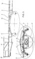
- the wagon platform according to the invention has two side members lateral 1, each spar being in five parts: one part central 1a, connected at each end to a reinforced part 1b, each part 1b being connected to an end part 1c.
- Each spar therefore consists of one end at the other by a terminal element 1c, an intermediate element reinforced 1b, a central element 1a, an intermediate element reinforced 1b, a terminal element 1c.
- the spar elements 1c are identical to the central part 1a but the invention is not limited to this specific detail.
- each spar element 1b has a notch 2 which has for purpose of allowing the wheel 3 of the rolling member to debate at height without its axis 4 hitting the spar 1.
- This notch 2 obviously has the effect of weakening the resistance of element 1b: by referring to FIGS. 4 and 6, we see that to compensate for this weakening the width of item 1b is increased, it is almost double that of the other elements 1a and 1c of the beam 1.
- This scaffolded and reinforced longitudinal member 1b carries the two usual brackets 5 to which the springs 6 are coupled by the binoculars 7, the springs 6 being arranged in position reversed in order to contribute to lowering the plate.
- the anchor box 8 by means of which the corners of the containers are fixed to the wagon platform are carried by the end parts 1c of each lateral spar 1.
- the anchor box 8 can advantageously have reinforcing pieces 9 between each housing 8 and the end of the reinforced spar element 1b corresponding.
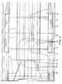
- the tray of the wagon is constituted by four longitudinal beams 10, parallel, arranged between the two side rails 1.
- these longitudinal members 10 are fairly thin sections, because these longitudinal members have practically no bending forces to absorb the fact that these efforts are supported by the container itself which rests on the tray only by its four corners fixed to the four boxes 9.
- this longitudinal structure constituted by the four side rails 10 arranged between the two side rails 1, risk of poorly withstanding torsional forces along the axis longitudinal median of the wagon.
- the tray of the wagon thus produced is so low that it is not possible to arrange the knockers or pads 20 in the extension of the tray receiving the containers.
- each spar 1 is slightly folded upwards and two of the side members 10 are cut at the place of the fold so that they don't go to the end of the tray.
- a vertical cross plate 21 is welded to the end of the two cut longitudinal members while being crossed by the other two to which it is welded.
- the two longitudinal members 10 which are not cut are those in the center.
- the plates 21 and 23 rise vertically from sufficient height for the pads 20 which are attached to the plate 23 are at the desired level, above the wagon platform. Elements 21, 22 and 23 constitute a raised boxwork by compared to the plateau.
- the lowered wagons and light structure described above are intended to be grouped together to form modular sets while remaining permanently hitched to each other.
- a module consists of four cars, and only the two ends of the assembly modular have two buffers 20.
- the wagon shown in Figure 1 is the wagon of the end on the right and the wagon on the other end, located on the left will be in an inverted symmetrical position, so that the module only has raised pads 20 at both extremities.
- connections between the wagons inside the module at four wagons are not then made by pairs of buffers such as the pairs of pads 20 which have a spacing, a standard height and dimensions; but by a tampon single 30 simply placed at the end of the longitudinal members 10. A the location corresponding to the missing buffer is placed a plate 31 against which single buffer 30 of the other wagon goes come and take support.
- the two cars located in the middle of the module of four wagons don't have buffers like 20 pads but only unique stamps such as stamp 30.
- the preferential module consists of four wagons, but it can just as easily have more or less wagons.
- the wagons are identical to that shown in Figure 1, but in position reversed; when it has more, the two end cars are similar to the wagon in Figure 1, but in the inverted position and between these two wagons we can have one, two, three or more, these wagons having at each end only a buffer 30 unique.
Landscapes
- Engineering & Computer Science (AREA)
- Mechanical Engineering (AREA)
- Handcart (AREA)
- Accommodation For Nursing Or Treatment Tables (AREA)
Claims (9)
- Containertragwagen, der flachgewölbt und in Leichtbauweise ausgeführt ist, dadurch gekennzeichnet, daß er zwei seitliche Längsträger (1) umfaßt, welche die Rollorgane (3, 4) aufweisen, wobei jeder seitliche Längsträger aus fünf Elementen besteht, nämlich aus einem mittleren Element (1a), zwei Endelementen (1c) und zwei verstärkten Elementen (1b), welche die Rollorgane tragen, wobei die verstärkten Elemente (1b) eine Aussparung (2) aufweisen, um die Ausfederung des Rades oder der Räder (3), die von kleinem Durchmesser sind, zuzulassen, wobei Träger (5) die Blattfedern (6) tragen und die letzteren sich in umgekehrter Stellung befinden.
- Containertragwagen nach Anspruch 1, dadurch gekennzeichnet, daß das Plateau des Wagens aus sechs Längsträgern gebildet wird, wobei die vier Längsträger (10), die zwischen den seitlichen Längsträgern (1) liegen, Stahlleichtprofile sind.
- Containertragwagen nach Anspruch 2, bei dem der Boden in seiner Mitte mit zwei X-förmig gekreuzten Stegen (11) verstärkt ist.
- Containertragwagen nach Anspruch 3, bei dem jedes ausgesparte und verstärkte Element (1b) der seitlichen Längsträger (1) von zwei Querstreben (12) eingerahmt ist.
- Containertragwagen nach Anspruch 4, bei dem jeder seitliche Längsträger (1) durch einen zusätzlichen Längsträger (14) verstärkt ist, der mit dem seitlichen Längsträger (1) über Verbindungsstücke (15) verbunden ist, die einen integralen Bestandteil der verstärkten Elemente (1b) rechtwinklig zu den Vertiefungen (2) bilden.
- Containertragwagen nach Anspruch 5, dadurch gekennzeichnet, daß die genormten Gehäuse (8) zur Befestigung der Ecken der Behälter auf den Endteilen (1c) der Längsträger (1) angebracht sind, wobei diese Endteile mit Verstärkungsteilen (9) verstärkt sind, die zwischen den Gehäusen (8) und dem verstärkten Element (1b) des Längsträgers (1) angeordnet sind.
- Containertragwagen nach einem der Ansprüche 1 bis 6, dadurch gekennzeichnet, daß er nur an einem seiner Enden Puffer (20) aufweist, wobei diese Puffer (20) von einem Kastensystem (21, 22, 23) getragen werden, das höher als der Boden des Wagens angebracht ist.
- Containertragwagen nach Anspruch 7, dadurch gekennzeichnet, daß er an seinem Ende, das dem mit über dem Boden angebrachten Puffern (20) versehenen Ende gegenüberliegt, einen einzigen Puffer (30) aufweist, der in der Ebene des Bodens in Höhe der Längsträger (10) angebracht ist.
- Modulare Einheit von Containertragwagen, dadurch gekennzeichnet, daß sie aus einer Vielzahl von Wagen nach den Ansprüchen 1 bis 8 besteht, wobei die beiden Endwagen an einem ihrer Enden, das nach außen gerichtet ist, ein Paar von höher liegenden Puffern (20) und an ihrem anderen Ende einen einzigen Puffer (30) auf der Höhe des Bodens umfassen, wobei die zwischen diesen beiden Endwagen befindlichen Wagen nur mit Einzelpuffern (30) ausgestattet sind.
Applications Claiming Priority (2)
| Application Number | Priority Date | Filing Date | Title |
|---|---|---|---|
| FR9603830A FR2746754B1 (fr) | 1996-03-27 | 1996-03-27 | Perfectionnements aux wagons de chemin de fer porte-conteneurs |
| FR9603830 | 1996-03-27 |
Publications (2)
| Publication Number | Publication Date |
|---|---|
| EP0798191A1 EP0798191A1 (de) | 1997-10-01 |
| EP0798191B1 true EP0798191B1 (de) | 1999-11-17 |
Family
ID=9490612
Family Applications (1)
| Application Number | Title | Priority Date | Filing Date |
|---|---|---|---|
| EP19970400675 Expired - Lifetime EP0798191B1 (de) | 1996-03-27 | 1997-03-26 | Verbesserungen an Container-tragenden Eisenbahnwaggons |
Country Status (4)
| Country | Link |
|---|---|
| EP (1) | EP0798191B1 (de) |
| DE (1) | DE69700794T2 (de) |
| ES (1) | ES2142135T3 (de) |
| FR (1) | FR2746754B1 (de) |
Families Citing this family (1)
| Publication number | Priority date | Publication date | Assignee | Title |
|---|---|---|---|---|
| PL132388U1 (pl) * | 2024-10-04 | 2026-04-07 | Wagony Świdnica Spółka Z Ograniczoną Odpowiedzialnością | Zestaw ograniczników w układzie biegowym wagonów dwuosiowych |
Family Cites Families (2)
| Publication number | Priority date | Publication date | Assignee | Title |
|---|---|---|---|---|
| DE3808800A1 (de) * | 1988-03-16 | 1989-10-05 | Graaff Kg | Untergestell fuer eisenbahngueterwagen |
| FR2711600B1 (fr) * | 1993-10-28 | 1996-01-05 | Arbel Fauvet Rail Sa | Suspension simple essieu pour une plate-forme de transport ferroviaire. |
-
1996
- 1996-03-27 FR FR9603830A patent/FR2746754B1/fr not_active Expired - Fee Related
-
1997
- 1997-03-26 DE DE1997600794 patent/DE69700794T2/de not_active Expired - Fee Related
- 1997-03-26 ES ES97400675T patent/ES2142135T3/es not_active Expired - Lifetime
- 1997-03-26 EP EP19970400675 patent/EP0798191B1/de not_active Expired - Lifetime
Also Published As
| Publication number | Publication date |
|---|---|
| EP0798191A1 (de) | 1997-10-01 |
| DE69700794T2 (de) | 2000-06-29 |
| FR2746754A1 (fr) | 1997-10-03 |
| FR2746754B1 (fr) | 1998-05-15 |
| ES2142135T3 (es) | 2000-04-01 |
| DE69700794D1 (de) | 1999-12-23 |
Similar Documents
| Publication | Publication Date | Title |
|---|---|---|
| CA2649218C (fr) | Plancher d'aeronef, utilisation d'un tel plancher et troncon d'aeronef muni d'un tel plancher | |
| CA2589933C (fr) | Ensemble structurel d'extremite de caisse de voiture ferroviaire | |
| EP1292478A1 (de) | Waggon für den kombinierten schienen/strassen- transpport mit zwei endseitigen plattformen, die eine drehbare tragstruktur für den lastkraftwagen tragen | |
| FR2659925A1 (fr) | Voiture de chemin de fer a applications multiples. | |
| EP0798191B1 (de) | Verbesserungen an Container-tragenden Eisenbahnwaggons | |
| CH623783A5 (de) | ||
| FR2760712A1 (fr) | Wagon porte-conteneurs | |
| FR2702441A1 (fr) | Structure support intermédiaire pour plateau basculant de véhicule utilitaire. | |
| EP0277059B1 (de) | Schienenfahrzeug mit Lastverteilung auf die vier bezüglich des Aufbaus einstellbaren Achsen | |
| FR2473018A1 (fr) | Conteneur-citerne comprenant une cuve retenue a l'interieur d'une ossature parallelepipedique | |
| EP0026680B1 (de) | Plattform für den Transport grosser Glasplatten | |
| FR2913654A1 (fr) | Boggie,notamment pour wagon de transport de marchandises. | |
| FR2625965A1 (fr) | Bogie de chemin de fer a trois essieux | |
| EP1227961A1 (de) | Erweiterbares drehgestell, insbesondere für eisenbahngüterwagen | |
| FR2828457A1 (fr) | Vehicules et rames ferroviaires ou routiers a niveau variable induit par roulement accessoire pour transports a grand gabarit | |
| FR2526386A1 (fr) | Suspension primaire pour vehicule ferroviaire et dispositif de reaction longitudinale | |
| FR2755417A1 (fr) | Wagon de chemin de fer dont le chassis comporte des longerons centraux | |
| EP3642124B1 (de) | Kombination aus einer transportpalette für rollwagen und einem oder mehreren rollwagen | |
| FR2544674A1 (fr) | Remorque porte-velos | |
| BE545995A (de) | ||
| EP0465367A1 (de) | Fahrzeug für Eisenbahnverkehr | |
| EP0827897A2 (de) | Fahrschemelvorrichtung für selbsttragende Sattelfahrzeuge oder Anhänger | |
| FR3068011B1 (fr) | Palette de transport de chariots comportant des organes de blocage | |
| FR2682068A1 (fr) | Unite routiere rail/route a rallonge d'extremite. | |
| FR3162179A1 (fr) | Dispositif d’emport de quadricycle pour tracteur agricole |
Legal Events
| Date | Code | Title | Description |
|---|---|---|---|
| PUAI | Public reference made under article 153(3) epc to a published international application that has entered the european phase |
Free format text: ORIGINAL CODE: 0009012 |
|
| AK | Designated contracting states |
Kind code of ref document: A1 Designated state(s): DE ES FR |
|
| 17P | Request for examination filed |
Effective date: 19980324 |
|
| GRAG | Despatch of communication of intention to grant |
Free format text: ORIGINAL CODE: EPIDOS AGRA |
|
| 17Q | First examination report despatched |
Effective date: 19990329 |
|
| GRAG | Despatch of communication of intention to grant |
Free format text: ORIGINAL CODE: EPIDOS AGRA |
|
| GRAH | Despatch of communication of intention to grant a patent |
Free format text: ORIGINAL CODE: EPIDOS IGRA |
|
| GRAH | Despatch of communication of intention to grant a patent |
Free format text: ORIGINAL CODE: EPIDOS IGRA |
|
| GRAA | (expected) grant |
Free format text: ORIGINAL CODE: 0009210 |
|
| AK | Designated contracting states |
Kind code of ref document: B1 Designated state(s): DE ES FR |
|
| REF | Corresponds to: |
Ref document number: 69700794 Country of ref document: DE Date of ref document: 19991223 |
|
| REG | Reference to a national code |
Ref country code: ES Ref legal event code: FG2A Ref document number: 2142135 Country of ref document: ES Kind code of ref document: T3 |
|
| PLBE | No opposition filed within time limit |
Free format text: ORIGINAL CODE: 0009261 |
|
| STAA | Information on the status of an ep patent application or granted ep patent |
Free format text: STATUS: NO OPPOSITION FILED WITHIN TIME LIMIT |
|
| 26N | No opposition filed | ||
| REG | Reference to a national code |
Ref country code: FR Ref legal event code: TP |
|
| PGFP | Annual fee paid to national office [announced via postgrant information from national office to epo] |
Ref country code: FR Payment date: 20040331 Year of fee payment: 8 |
|
| PGFP | Annual fee paid to national office [announced via postgrant information from national office to epo] |
Ref country code: DE Payment date: 20040406 Year of fee payment: 8 |
|
| PGFP | Annual fee paid to national office [announced via postgrant information from national office to epo] |
Ref country code: ES Payment date: 20040419 Year of fee payment: 8 |
|
| PG25 | Lapsed in a contracting state [announced via postgrant information from national office to epo] |
Ref country code: ES Free format text: LAPSE BECAUSE OF NON-PAYMENT OF DUE FEES Effective date: 20050328 |
|
| PG25 | Lapsed in a contracting state [announced via postgrant information from national office to epo] |
Ref country code: DE Free format text: LAPSE BECAUSE OF NON-PAYMENT OF DUE FEES Effective date: 20051001 |
|
| PG25 | Lapsed in a contracting state [announced via postgrant information from national office to epo] |
Ref country code: FR Free format text: LAPSE BECAUSE OF NON-PAYMENT OF DUE FEES Effective date: 20051130 |
|
| REG | Reference to a national code |
Ref country code: FR Ref legal event code: ST Effective date: 20051130 |
|
| REG | Reference to a national code |
Ref country code: ES Ref legal event code: FD2A Effective date: 20050328 |