EP0798147A2 - Gangschaltgerät für ein automatisches Getriebe - Google Patents
Gangschaltgerät für ein automatisches Getriebe Download PDFInfo
- Publication number
- EP0798147A2 EP0798147A2 EP97103793A EP97103793A EP0798147A2 EP 0798147 A2 EP0798147 A2 EP 0798147A2 EP 97103793 A EP97103793 A EP 97103793A EP 97103793 A EP97103793 A EP 97103793A EP 0798147 A2 EP0798147 A2 EP 0798147A2
- Authority
- EP
- European Patent Office
- Prior art keywords
- gear
- lever
- selector lever
- shift device
- transmission member
- Prior art date
- Legal status (The legal status is an assumption and is not a legal conclusion. Google has not performed a legal analysis and makes no representation as to the accuracy of the status listed.)
- Ceased
Links
Images

Classifications
-
- F—MECHANICAL ENGINEERING; LIGHTING; HEATING; WEAPONS; BLASTING
- F16—ENGINEERING ELEMENTS AND UNITS; GENERAL MEASURES FOR PRODUCING AND MAINTAINING EFFECTIVE FUNCTIONING OF MACHINES OR INSTALLATIONS; THERMAL INSULATION IN GENERAL
- F16H—GEARING
- F16H59/00—Control inputs to control units of change-speed- or reversing-gearings for conveying rotary motion
- F16H59/02—Selector apparatus
- F16H59/08—Range selector apparatus
- F16H59/10—Range selector apparatus comprising levers
-
- F—MECHANICAL ENGINEERING; LIGHTING; HEATING; WEAPONS; BLASTING
- F16—ENGINEERING ELEMENTS AND UNITS; GENERAL MEASURES FOR PRODUCING AND MAINTAINING EFFECTIVE FUNCTIONING OF MACHINES OR INSTALLATIONS; THERMAL INSULATION IN GENERAL
- F16H—GEARING
- F16H59/00—Control inputs to control units of change-speed- or reversing-gearings for conveying rotary motion
- F16H59/02—Selector apparatus
- F16H59/0204—Selector apparatus for automatic transmissions with means for range selection and manual shifting, e.g. range selector with tiptronic
-
- B—PERFORMING OPERATIONS; TRANSPORTING
- B60—VEHICLES IN GENERAL
- B60K—ARRANGEMENT OR MOUNTING OF PROPULSION UNITS OR OF TRANSMISSIONS IN VEHICLES; ARRANGEMENT OR MOUNTING OF PLURAL DIVERSE PRIME-MOVERS IN VEHICLES; AUXILIARY DRIVES FOR VEHICLES; INSTRUMENTATION OR DASHBOARDS FOR VEHICLES; ARRANGEMENTS IN CONNECTION WITH COOLING, AIR INTAKE, GAS EXHAUST OR FUEL SUPPLY OF PROPULSION UNITS IN VEHICLES
- B60K20/00—Arrangement or mounting of change-speed gearing control devices in vehicles
- B60K20/02—Arrangement or mounting of change-speed gearing control devices in vehicles of initiating means
-
- F—MECHANICAL ENGINEERING; LIGHTING; HEATING; WEAPONS; BLASTING
- F16—ENGINEERING ELEMENTS AND UNITS; GENERAL MEASURES FOR PRODUCING AND MAINTAINING EFFECTIVE FUNCTIONING OF MACHINES OR INSTALLATIONS; THERMAL INSULATION IN GENERAL
- F16H—GEARING
- F16H59/00—Control inputs to control units of change-speed- or reversing-gearings for conveying rotary motion
- F16H59/02—Selector apparatus
- F16H2059/0239—Up- and down-shift or range or mode selection by repeated movement
-
- Y—GENERAL TAGGING OF NEW TECHNOLOGICAL DEVELOPMENTS; GENERAL TAGGING OF CROSS-SECTIONAL TECHNOLOGIES SPANNING OVER SEVERAL SECTIONS OF THE IPC; TECHNICAL SUBJECTS COVERED BY FORMER USPC CROSS-REFERENCE ART COLLECTIONS [XRACs] AND DIGESTS
- Y10—TECHNICAL SUBJECTS COVERED BY FORMER USPC
- Y10T—TECHNICAL SUBJECTS COVERED BY FORMER US CLASSIFICATION
- Y10T74/00—Machine element or mechanism
- Y10T74/20—Control lever and linkage systems
- Y10T74/20012—Multiple controlled elements
- Y10T74/20018—Transmission control
- Y10T74/20049—Transmission controlled by flexible cable
-
- Y—GENERAL TAGGING OF NEW TECHNOLOGICAL DEVELOPMENTS; GENERAL TAGGING OF CROSS-SECTIONAL TECHNOLOGIES SPANNING OVER SEVERAL SECTIONS OF THE IPC; TECHNICAL SUBJECTS COVERED BY FORMER USPC CROSS-REFERENCE ART COLLECTIONS [XRACs] AND DIGESTS
- Y10—TECHNICAL SUBJECTS COVERED BY FORMER USPC
- Y10T—TECHNICAL SUBJECTS COVERED BY FORMER US CLASSIFICATION
- Y10T74/00—Machine element or mechanism
- Y10T74/20—Control lever and linkage systems
- Y10T74/20012—Multiple controlled elements
- Y10T74/20018—Transmission control
- Y10T74/20067—Control convertible between automatic and manual operation
Definitions
- the invention relates to a gear-shift device for an automatic gearbox of a motor vehicle according to the preamble of Claim 1.
- a gear-shift device for an automatic gearbox of a motor vehicle is already known from EP 0 413 116 B1.
- the movement of a selector lever is taken up by an entrainment means and is transmitted to an actuating lever.
- An actuating rod mounted on the actuating lever then leads to the gearbox.
- the selector lever and the entrainment means are mounted on a common shaft.
- the gear-shift device shown has a large structural depth since the actuating lever is situated opposite the selector lever.
- the gear-shift device illustrated is obviously intended for insertion in an aperture in the body, the selector lever being arranged on one side of the body and the actuating lever on the other.
- the object of the present invention is to provide a gear-shift device for an automatic gearbox which is suitable for mounting on a body, i.e. does not penetrate the body.
- a gear-shift device comprising a pivotably mounted selector lever for actuation by the driver, a pivotably mounted actuating lever linked thereto, and a transmission member which is articulated to the actuating lever and which acts upon the automatic gearbox, in such a way that the gear-shift device is arranged on the surface of a body, the selector lever is mounted close to the said surface, the articulation point of the transmission member on the actuating lever is formed close to the said surface, and the coupling point is situated on the selector lever between the pivot shaft and an actuating face of the selector lever.
- an actuating face is to be understood as being that face of the selector lever which is gripped by the driver in order to actuate the selector lever.
- both the pivot shaft of the selector lever and the guide of the transmission member leading to the gearbox are situated close to the body.
- the actuating stroke produced at the transmission member can be set without fundamental structural alterations, so that the gear-shift device can be adapted to various gearboxes, and in particular while retaining the movement ratios on the selector lever.
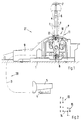
- Fig. 1 shows a gear-shift device 1 which is held on a body 1 and which is connected to a control slide 4 of an automatic gearbox 5 by a Bowden cable 3 acting as a transmission means.
- the gear-shift device 1 comprises a selector lever 6, which has a push button 7, a transmission lever 8, which is connected to the Bowden cable 3, a housing 9, a locking device 10 and a locking means 11.
- An indented guide slot 12 is formed in the housing 9 and is part of both the locking device 10 and the locking means 11.
- a first gear-shift gate 13 has the positions P , R , N and D , as known in a conventional manner for the automatic operation of the automatic gearbox 5.
- the locking means 11 is not unlocked by pressing the push button 7, the selector lever 6 is held firmly in these positions in the first gear-shift gate 13 by the locking means 11 which cooperates with the indented guide slot 12; in the illustration according to Fig. 1 the selector lever 6 is in position N .
- the push button 7 at the same time forms the upper boundary of the actuating face of the selector lever 6.
- the selector lever can be pivoted by way of a transverse gate 14 into the second gear-shift gate 15 which is arranged parallel to the first gear-shift gate 13.
- the selector lever 6 occupies a neutral central position M under the action of a spring and can be moved out of the said position M by longitudinal pivoting inside the second gear-shift gate 15 into a position "+” or in the opposite direction into a position "-".
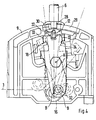
- the transmission lever 8 is linked to a second lever 16 which has a slide 17.
- the transmission lever 8 is mounted pivotably on a shaft A .
- the second lever 16 is likewise mounted pivotably on a shaft B , which extends parallel to and at a distance d from the shaft A , and it is linked to the transmission lever 8 in an area 18.
- the slide 17 is held by means of a guide 19 on the second lever 16 and is held there pre-stressed by a spring 20 in the direction of the indented guide slot 12.
- a further slide 21, which has a pin 22, is provided on the selector lever 6 which is pivotable transversely to the first gear-shift gate 13 about a shaft C .
- the slide 21 is held by a spring 23 in its rest position illustrated.
- a thrust rod 24 connects the push button 7 to the slide 21.
- the shaft C is formed in an intermediate member 25 which in turn is mounted in the housing 9 by a shaft B which extends at right angles to the shaft C .
- the shaft B allows the selector lever 6 to be pivoted in the longitudinal direction both of the first gear-shift gate 13 and of the second gear-shift gate 15.
- a spring-loaded catch member 26 cooperates with a pin 27 mounted on the selector lever 6, in such a way that the selector lever 6 occupies either a position in the first gear-shift gate 13 or a position in the second gear-shift gate 15 during movement along the transverse gate 14 without remaining in an intermediate position.
- a guide finger 28 arranged on the selector lever 6 above the slide 21 engages in a groove 29 which is formed in the housing 9.
- the selector lever 6 is guided in the first gear-shift gate 13.
- the groove 29 opens out to form a transverse groove 30, so that the selector lever 6 can now move along the transverse gate 14.
- the guide finger 28 is guided with slight play both in the groove 29 and in the transverse groove 30.
- the shaft A on which the transmission lever 8 is mounted, is formed by a bolt 31 screwed into the housing 9.
- a ball end 32 for fastening the Bowden cable 3 is provided at one end of the transmission lever 8, whereas two spaced projections 33 are formed at the opposite end of the transmission lever 8.
- the ball end 32 comes to be situated adjacent to the body 1 to which the gear-shift device 2 is secured.
- the Bowden cable 3 can be guided therewith at a slight distance from the body 1.
- the second lever 16 on the other hand, is mounted at one end thereof on the shaft B and is provided at the opposite end with a bulging area 34.
- Two projections 35 are provided therebetween, the said projections 35 embracing the selector lever 6 when it is in the first gear-shift gate 13, so that the second lever 16 moves in synchronism with the selector lever 6.
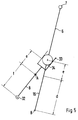
- Fig. 5 shows once more the linking of the transmission lever 8 to the second lever 16 by way of a diagram.
- the path covered on the ball end 32 depends primarily upon the ratios of the distances d , e and f , the distance d being formed between the shafts A and B , the distance e being formed between the shaft A and the centre of the bulging area 34, and the distance f being formed between the shaft A and the centre of the ball end 32. Since the position of the shafts A and B and therefore the distance d can be altered only by altering the design of the housing 9, the distance d is to be regarded as being essentially invariable.
- the operating path on the ball end 32 is thus preferably set by altering the distances e and f , which in turn depend only on the shape of the transmission lever 8 and of the second lever 16. It is therefore possible to adapt the operating path on the ball end 32 in an extremely inexpensive manner by simply altering two sheet-metal [ sic ] components, namely the transmission lever 8 and the second lever 16.
- the distance f can be chosen to be such that the ball end 32 and together therewith the Bowden cable 3 extend at a slight distance from the body 1, so that the Bowden cable 3 can be secured and set on the body 1 without additional means, such as for example spacer blocks.
Landscapes
- Engineering & Computer Science (AREA)
- General Engineering & Computer Science (AREA)
- Mechanical Engineering (AREA)
- Arrangement Or Mounting Of Control Devices For Change-Speed Gearing (AREA)
- Gear-Shifting Mechanisms (AREA)
- Control Of Transmission Device (AREA)
Applications Claiming Priority (2)
| Application Number | Priority Date | Filing Date | Title |
|---|---|---|---|
| IT96TO000248A IT1286288B1 (it) | 1996-03-29 | 1996-03-29 | Dispositivo di comando per un cambio automatico |
| ITTO960248 | 1996-03-29 |
Publications (2)
| Publication Number | Publication Date |
|---|---|
| EP0798147A2 true EP0798147A2 (de) | 1997-10-01 |
| EP0798147A3 EP0798147A3 (de) | 1998-11-25 |
Family
ID=11414504
Family Applications (1)
| Application Number | Title | Priority Date | Filing Date |
|---|---|---|---|
| EP97103793A Ceased EP0798147A3 (de) | 1996-03-29 | 1997-03-07 | Gangschaltgerät für ein automatisches Getriebe |
Country Status (5)
| Country | Link |
|---|---|
| US (1) | US5870929A (de) |
| EP (1) | EP0798147A3 (de) |
| JP (1) | JPH1029443A (de) |
| KR (1) | KR970065084A (de) |
| IT (1) | IT1286288B1 (de) |
Cited By (1)
| Publication number | Priority date | Publication date | Assignee | Title |
|---|---|---|---|---|
| EP0997669A3 (de) * | 1998-10-30 | 2002-08-21 | FUJI KIKO Co., Ltd. | Schalthebelvorrichtung für Automatikgetriebe mit Handschaltmodus |
Families Citing this family (9)
| Publication number | Priority date | Publication date | Assignee | Title |
|---|---|---|---|---|
| DE19720327C1 (de) * | 1997-05-15 | 1998-04-30 | Preh Elektro Feinmechanik | Bedienelement |
| JP3840330B2 (ja) * | 1998-02-10 | 2006-11-01 | マツダ株式会社 | 自動変速機の変速操作入力装置 |
| US6295886B1 (en) | 1998-10-08 | 2001-10-02 | Dura Global Technologies | Vehicle shift mechanism for an automatic transmission |
| DE19937698C2 (de) * | 1999-08-10 | 2001-09-13 | Zf Lemfoerder Metallwaren Ag | Schaltvorrichtung eines automatischen Kraftfahrzeuggetriebes |
| US6382046B1 (en) | 2000-02-09 | 2002-05-07 | Dura Automotive Properties | Transmission shifter with cable disengagement mechanism |
| US6569058B2 (en) * | 2000-12-20 | 2003-05-27 | Daimlerchrysler Corporation | Linear motion shifter |
| JP3611111B2 (ja) * | 2001-04-17 | 2005-01-19 | 川崎重工業株式会社 | 車両用変速レバー装置 |
| DE102006034939A1 (de) * | 2006-07-28 | 2008-01-31 | Dr.Ing.H.C. F. Porsche Ag | Schaltvorrichtung für ein automatisiertes oder automatisches Getriebe |
| US8656802B2 (en) * | 2011-09-30 | 2014-02-25 | Kongsberg Automotive Ab | Shifter assembly for providing mechanical and electronic actuation to a transmission of a vehicle and a method of operating the shifter assembly |
Family Cites Families (5)
| Publication number | Priority date | Publication date | Assignee | Title |
|---|---|---|---|---|
| US4326432A (en) * | 1980-04-17 | 1982-04-27 | General Motors Corporation | Floor mounted transmission shift console |
| EP0307846B1 (de) * | 1987-09-14 | 1992-02-26 | Kabushiki Kaisha Tokai Rika Denki Seisakusho | Einrichtung zum Sperren des Schalthebels eines automatischen Getriebes |
| JPH03153957A (ja) * | 1989-11-09 | 1991-07-01 | Aisin Aw Co Ltd | 車両用自動変速機の手動選択装置 |
| EP0575658B1 (de) * | 1992-06-30 | 1998-10-28 | Aisin Aw Co., Ltd. | Schaltanlage mit manuellem Übersetzungswahlmechanismus für ein automatisches Kraftfahrzeuggetriebe |
| EP0736408B1 (de) * | 1995-04-08 | 1999-01-13 | Ford Global Technologies, Inc. | Wählhebelanordnung für automatische Getriebe für Kraftfahrzeuge mit manueller Schaltmöglichkeit |
-
1996
- 1996-03-29 IT IT96TO000248A patent/IT1286288B1/it active IP Right Grant
-
1997
- 1997-03-07 EP EP97103793A patent/EP0798147A3/de not_active Ceased
- 1997-03-28 KR KR1019970011201A patent/KR970065084A/ko not_active Ceased
- 1997-03-28 JP JP9077802A patent/JPH1029443A/ja active Pending
- 1997-03-31 US US08/829,289 patent/US5870929A/en not_active Expired - Fee Related
Cited By (1)
| Publication number | Priority date | Publication date | Assignee | Title |
|---|---|---|---|---|
| EP0997669A3 (de) * | 1998-10-30 | 2002-08-21 | FUJI KIKO Co., Ltd. | Schalthebelvorrichtung für Automatikgetriebe mit Handschaltmodus |
Also Published As
| Publication number | Publication date |
|---|---|
| US5870929A (en) | 1999-02-16 |
| ITTO960248A0 (de) | 1996-03-29 |
| ITTO960248A1 (it) | 1997-09-29 |
| EP0798147A3 (de) | 1998-11-25 |
| IT1286288B1 (it) | 1998-07-08 |
| JPH1029443A (ja) | 1998-02-03 |
| KR970065084A (ko) | 1997-10-13 |
Similar Documents
| Publication | Publication Date | Title |
|---|---|---|
| CA1118321A (en) | Manual transmission shifter for operating a transmission with flexible cables | |
| US5682789A (en) | Selector lever system for manually shiftable automatic transmissions | |
| EP0760917B1 (de) | Schaltmechanismus zum manuellen schalten eines automatischen getriebes | |
| US4328712A (en) | Lockout for gimbal-type automotive transmission gear shifter | |
| US4474085A (en) | Transmission floor shifter control with a park/lock mechanism | |
| US7137313B2 (en) | Shifting device for transmitting shift commands to an automatic transmission | |
| US4520640A (en) | Position control mechanism for a vehicle ignition lock | |
| US5794748A (en) | Park lock mechanism for an automatic transmission | |
| US5870929A (en) | Gear-shift device for an automatic gearbox | |
| USRE31451E (en) | Manual transmission shifter for operating a transmission with elongated actuators such as flexible cables | |
| US4986399A (en) | Shifter brake interlock system | |
| US20050028633A1 (en) | Shifting device for an automatic transmission | |
| US20050235769A1 (en) | Shift-by-wire shifting with P position | |
| US6931963B2 (en) | Automatic shift knob actuator | |
| US4532824A (en) | Automobile automatic transmission control device | |
| US6435052B1 (en) | Gearshift lever with locking bar | |
| CA1298171C (en) | Park position shift selector mechanism and method | |
| US6231476B1 (en) | Park-lock shifter cable | |
| US7131349B2 (en) | Device for actuating a gearbox and pulse control method | |
| EP0798148B1 (de) | Verriegelungseinrichtung für einen Schalthebel | |
| US6701798B2 (en) | Shift device for a motor vehicle gearbox | |
| US6915718B2 (en) | Selector handle in a motor vehicle | |
| EP0798146B1 (de) | Gasse für einen Schalthebel | |
| CA1228242A (en) | Position control mechanism for a vehicle ignition lock | |
| EP0443992A1 (de) | Schaltung für Fahrzeuggetriebe, insbesondere für landwirtschaftliche Traktoren |
Legal Events
| Date | Code | Title | Description |
|---|---|---|---|
| PUAI | Public reference made under article 153(3) epc to a published international application that has entered the european phase |
Free format text: ORIGINAL CODE: 0009012 |
|
| AK | Designated contracting states |
Kind code of ref document: A2 Designated state(s): DE ES FR GB IT NL SE |
|
| PUAL | Search report despatched |
Free format text: ORIGINAL CODE: 0009013 |
|
| AK | Designated contracting states |
Kind code of ref document: A3 Designated state(s): DE ES FR GB IT NL SE |
|
| 17P | Request for examination filed |
Effective date: 19990316 |
|
| 17Q | First examination report despatched |
Effective date: 19990503 |
|
| RAP1 | Party data changed (applicant data changed or rights of an application transferred) |
Owner name: DR.ING.H.C. F. PORSCHE AKTIENGESELLSCHAFT |
|
| STAA | Information on the status of an ep patent application or granted ep patent |
Free format text: STATUS: THE APPLICATION HAS BEEN REFUSED |
|
| 18R | Application refused |
Effective date: 20010330 |