EP0798037A2 - Verfahren zum Einspritzen von körnigem Feststoff in einem Wirbelschichtreaktor - Google Patents
Verfahren zum Einspritzen von körnigem Feststoff in einem Wirbelschichtreaktor Download PDFInfo
- Publication number
- EP0798037A2 EP0798037A2 EP97103438A EP97103438A EP0798037A2 EP 0798037 A2 EP0798037 A2 EP 0798037A2 EP 97103438 A EP97103438 A EP 97103438A EP 97103438 A EP97103438 A EP 97103438A EP 0798037 A2 EP0798037 A2 EP 0798037A2
- Authority
- EP
- European Patent Office
- Prior art keywords
- particulate material
- standpipe
- fluidized bed
- gas
- bed reactor
- Prior art date
- Legal status (The legal status is an assumption and is not a legal conclusion. Google has not performed a legal analysis and makes no representation as to the accuracy of the status listed.)
- Granted
Links
- 239000011236 particulate material Substances 0.000 title claims abstract description 78
- 238000000034 method Methods 0.000 title claims abstract description 37
- 238000005243 fluidization Methods 0.000 claims abstract description 25
- 239000007787 solid Substances 0.000 claims abstract description 12
- 239000000571 coke Substances 0.000 claims description 27
- 239000000203 mixture Substances 0.000 claims description 25
- 239000002245 particle Substances 0.000 claims description 18
- GWEVSGVZZGPLCZ-UHFFFAOYSA-N Titan oxide Chemical compound O=[Ti]=O GWEVSGVZZGPLCZ-UHFFFAOYSA-N 0.000 claims description 11
- 239000000463 material Substances 0.000 claims description 11
- 238000011144 upstream manufacturing Methods 0.000 claims description 2
- 239000007789 gas Substances 0.000 description 18
- RTAQQCXQSZGOHL-UHFFFAOYSA-N Titanium Chemical compound [Ti] RTAQQCXQSZGOHL-UHFFFAOYSA-N 0.000 description 13
- 239000010936 titanium Substances 0.000 description 13
- 229910052719 titanium Inorganic materials 0.000 description 13
- 238000005273 aeration Methods 0.000 description 9
- 238000012545 processing Methods 0.000 description 6
- 238000006243 chemical reaction Methods 0.000 description 5
- 239000003575 carbonaceous material Substances 0.000 description 4
- 238000002347 injection Methods 0.000 description 4
- 239000007924 injection Substances 0.000 description 4
- HCHKCACWOHOZIP-UHFFFAOYSA-N Zinc Chemical compound [Zn] HCHKCACWOHOZIP-UHFFFAOYSA-N 0.000 description 3
- 238000005660 chlorination reaction Methods 0.000 description 3
- 239000003245 coal Substances 0.000 description 3
- 238000002485 combustion reaction Methods 0.000 description 3
- 239000003208 petroleum Substances 0.000 description 3
- 238000007670 refining Methods 0.000 description 3
- 229910052725 zinc Inorganic materials 0.000 description 3
- 239000011701 zinc Substances 0.000 description 3
- ZAMOUSCENKQFHK-UHFFFAOYSA-N Chlorine atom Chemical compound [Cl] ZAMOUSCENKQFHK-UHFFFAOYSA-N 0.000 description 2
- XEEYBQQBJWHFJM-UHFFFAOYSA-N Iron Chemical compound [Fe] XEEYBQQBJWHFJM-UHFFFAOYSA-N 0.000 description 2
- QVGXLLKOCUKJST-UHFFFAOYSA-N atomic oxygen Chemical compound [O] QVGXLLKOCUKJST-UHFFFAOYSA-N 0.000 description 2
- 239000000460 chlorine Substances 0.000 description 2
- 229910052801 chlorine Inorganic materials 0.000 description 2
- 238000005516 engineering process Methods 0.000 description 2
- 229910052751 metal Inorganic materials 0.000 description 2
- 239000002184 metal Substances 0.000 description 2
- 229910001510 metal chloride Inorganic materials 0.000 description 2
- 229910052760 oxygen Inorganic materials 0.000 description 2
- 239000001301 oxygen Substances 0.000 description 2
- 239000000843 powder Substances 0.000 description 2
- 239000004576 sand Substances 0.000 description 2
- XJDNKRIXUMDJCW-UHFFFAOYSA-J titanium tetrachloride Chemical compound Cl[Ti](Cl)(Cl)Cl XJDNKRIXUMDJCW-UHFFFAOYSA-J 0.000 description 2
- 235000019738 Limestone Nutrition 0.000 description 1
- 238000009835 boiling Methods 0.000 description 1
- 239000006227 byproduct Substances 0.000 description 1
- 239000011329 calcined coke Substances 0.000 description 1
- 238000004939 coking Methods 0.000 description 1
- 230000000694 effects Effects 0.000 description 1
- 239000003344 environmental pollutant Substances 0.000 description 1
- 238000002474 experimental method Methods 0.000 description 1
- 239000010419 fine particle Substances 0.000 description 1
- 239000011521 glass Substances 0.000 description 1
- 230000005484 gravity Effects 0.000 description 1
- 229910052742 iron Inorganic materials 0.000 description 1
- YDZQQRWRVYGNER-UHFFFAOYSA-N iron;titanium;trihydrate Chemical compound O.O.O.[Ti].[Fe] YDZQQRWRVYGNER-UHFFFAOYSA-N 0.000 description 1
- 239000006028 limestone Substances 0.000 description 1
- 238000012423 maintenance Methods 0.000 description 1
- 150000002739 metals Chemical class 0.000 description 1
- 238000005065 mining Methods 0.000 description 1
- 239000007800 oxidant agent Substances 0.000 description 1
- 239000003415 peat Substances 0.000 description 1
- 239000002006 petroleum coke Substances 0.000 description 1
- 238000005504 petroleum refining Methods 0.000 description 1
- JTJMJGYZQZDUJJ-UHFFFAOYSA-N phencyclidine Chemical class C1CCCCN1C1(C=2C=CC=CC=2)CCCCC1 JTJMJGYZQZDUJJ-UHFFFAOYSA-N 0.000 description 1
- 239000000049 pigment Substances 0.000 description 1
- 231100000719 pollutant Toxicity 0.000 description 1
- 239000000047 product Substances 0.000 description 1
- 239000002893 slag Substances 0.000 description 1
- XTQHKBHJIVJGKJ-UHFFFAOYSA-N sulfur monoxide Chemical class S=O XTQHKBHJIVJGKJ-UHFFFAOYSA-N 0.000 description 1
- 229910052815 sulfur oxide Inorganic materials 0.000 description 1
- 239000000725 suspension Substances 0.000 description 1
- 239000004408 titanium dioxide Substances 0.000 description 1
- 239000002023 wood Substances 0.000 description 1
Images
Classifications
-
- B—PERFORMING OPERATIONS; TRANSPORTING
- B01—PHYSICAL OR CHEMICAL PROCESSES OR APPARATUS IN GENERAL
- B01J—CHEMICAL OR PHYSICAL PROCESSES, e.g. CATALYSIS OR COLLOID CHEMISTRY; THEIR RELEVANT APPARATUS
- B01J8/00—Chemical or physical processes in general, conducted in the presence of fluids and solid particles; Apparatus for such processes
- B01J8/18—Chemical or physical processes in general, conducted in the presence of fluids and solid particles; Apparatus for such processes with fluidised particles
- B01J8/24—Chemical or physical processes in general, conducted in the presence of fluids and solid particles; Apparatus for such processes with fluidised particles according to "fluidised-bed" technique
-
- B—PERFORMING OPERATIONS; TRANSPORTING
- B01—PHYSICAL OR CHEMICAL PROCESSES OR APPARATUS IN GENERAL
- B01J—CHEMICAL OR PHYSICAL PROCESSES, e.g. CATALYSIS OR COLLOID CHEMISTRY; THEIR RELEVANT APPARATUS
- B01J8/00—Chemical or physical processes in general, conducted in the presence of fluids and solid particles; Apparatus for such processes
- B01J8/0005—Catalytic processes under superatmospheric pressure
-
- B—PERFORMING OPERATIONS; TRANSPORTING
- B01—PHYSICAL OR CHEMICAL PROCESSES OR APPARATUS IN GENERAL
- B01J—CHEMICAL OR PHYSICAL PROCESSES, e.g. CATALYSIS OR COLLOID CHEMISTRY; THEIR RELEVANT APPARATUS
- B01J8/00—Chemical or physical processes in general, conducted in the presence of fluids and solid particles; Apparatus for such processes
- B01J8/0015—Feeding of the particles in the reactor; Evacuation of the particles out of the reactor
- B01J8/003—Feeding of the particles in the reactor; Evacuation of the particles out of the reactor in a downward flow
-
- B—PERFORMING OPERATIONS; TRANSPORTING
- B01—PHYSICAL OR CHEMICAL PROCESSES OR APPARATUS IN GENERAL
- B01J—CHEMICAL OR PHYSICAL PROCESSES, e.g. CATALYSIS OR COLLOID CHEMISTRY; THEIR RELEVANT APPARATUS
- B01J2208/00—Processes carried out in the presence of solid particles; Reactors therefor
- B01J2208/00743—Feeding or discharging of solids
- B01J2208/00752—Feeding
-
- Y—GENERAL TAGGING OF NEW TECHNOLOGICAL DEVELOPMENTS; GENERAL TAGGING OF CROSS-SECTIONAL TECHNOLOGIES SPANNING OVER SEVERAL SECTIONS OF THE IPC; TECHNICAL SUBJECTS COVERED BY FORMER USPC CROSS-REFERENCE ART COLLECTIONS [XRACs] AND DIGESTS
- Y10—TECHNICAL SUBJECTS COVERED BY FORMER USPC
- Y10S—TECHNICAL SUBJECTS COVERED BY FORMER USPC CROSS-REFERENCE ART COLLECTIONS [XRACs] AND DIGESTS
- Y10S423/00—Chemistry of inorganic compounds
- Y10S423/09—Reaction techniques
- Y10S423/16—Fluidization
Definitions
- This invention relates to an improved method for injecting particulate material into a fluidized bed reactor.
- Fluidized bed processes are used commercially for the chlorination of titanium containing materials, ore roasting or refining, petroleum processing and refining, combustion of solid carbonaceous material such as coal, etc.
- particulate material a suitable fluidizing gas such as air, oxygen or other oxidizing agents are fed into a reaction chamber, and the desired temperature and pressure are maintained. As necessary, the flow rates are adjusted so that the particulate material becomes fluidised, i.e., it is maintained in a state of suspension and has the appearance of boiling.
- a suitable fluidizing gas such as air, oxygen or other oxidizing agents
- a good example of a commercial fluidized bed process is that for chlorinating titanium containing material.
- particulate coke, particulate titanium containing material, chlorine and optionally oxygen or air are fed into a reaction chamber, and a suitable reaction temperature, pressure and flow rates are maintained to sustain the fluidized bed.
- Gaseous titanium tetrachloride and other metal chlorides are exhausted from the reactor chamber. The gaseous titanium tetrachloride so produced can then be separated from the other metal chlorides and used to produce titanium dioxide pigment or titanium metal.
- Fluidization has many advantages, but also can present certain problems. For example, if the particle size distribution is wide, a gas flow sufficient to fluidize the large particles may blow unreacted small particles out of the fluidized bed. Conversely, a gas flow just sufficient to fluidize the fine particles may not be sufficient to fluidize the large particles.
- Commonly used pneumatic feed where significant amounts of air or other gas is used to transport the particulate materials to the fluidized bed reactor, can also be a problem. For example, the air or gas injected can aggravate the problem of fines being blown out of the reactor.
- pneumatic feed is undesirable because of the reasons previously mentioned.
- mechanical feed devices are undesirable because they can have significant wear and maintenance costs.
- U.S. Patent 5,320,815 discloses a process for feeding fine, particulate material to a fluidized bed.
- U.S. Patents, 5,325,603 and 5,175,943 disclose a process and an apparatus for feeding particulate material to a fluidized bed reactor.
- "Effects of System and Geometrical Parameters on the Flow of Class B Solids in Overflow Standpipes, R. A. Sauer", I. H. Chan, and T. M. Knowlton, American Institute of Chemical Engineers Symposium Series No. 234, Vol. 80, (1983) discloses various parameters for operating standpipes.
- a process for feeding particulate material to a fluidized bed reactor comprising:
- the process of this invention can inject particulate material into a fluidized bed without the use of a mechanical feed device.
- the process of this invention can also inject particulate material into a fluidized bed without the addition of significant amounts of gas or air and without conveying the particulate material pneumatically.
- the process of this invention is especially useful for feeding particulate materials to fluidized bed reactors operating at greater than atmospheric pressure.
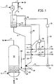
- Fig. 1 discloses an embodiment of this invention. It is used to feed a simulated fluidized bed reactor described in the Example.
- fluidized bed reactor any fluidized bed where chemical reactions, physical processing, mixing, contacting or transferring takes place.
- fluidized bed reactors that can utilize the concept of this invention include combustion of carbonaceous material (such as coal, wood, peat, etc.); ore refining or roasting (such as chlorination of titanium containing material); processing of metallic ores including those containing zinc, cooper or iron; and petroleum processing.
- the process of this invention is especially useful for introducing particulate material into fluidized bed reactors that are operating at greater than atmospheric pressure.
- the particulate material can have any particle size range that functions satisfactorily in the process of this invention. Typically, the particulate material will have a particle size of about 1-5000 microns. Often, the mean particle size will be about 100-500 microns. If particulate material is used that has a particle size of about 1-50 microns, then preferably it will not exceed 50 percent by weight of the total amount of particulate material.
- the particulate material will be Type B, as defined by D. Geldart, Types of Fluidization, Powder Technology, Volume 7, pages 285-292 (1973), which is hereby incorporated by reference.
- such particulate material is bubbly and behaves similarly to beach sand.
- Dense particulate materials such as glass, sand, ore and light particles over about 150 microns are likely to be Type B.
- Such particles display essentially no cohesive properties; therefore, once the minimum fluidization velocity is exceeded, most of the excess gas appears in the form of gas bubbles. See also chapter 1, page 3-4 of Gas Fluidization by M. Pell, which is volume 8 of the Handbook of Powder Technology, published by Elsevier in 1990. This publication is also hereby incorporated by reference.
- Typical conditions for commercial fluidized beds for chlorinating titanium containing material are as follows: reaction temperature of about 900° - 1300°C., pressure of about 1.5-3 atmospheres, reactor size of about 6-25 feet in diameter with multiple chlorine jets in the base, reactor superficial velocity of about 0.5-1.5 feet per second, and a settled bed depth of about 6-25 feet.
- the titanium containing material initially fed has a particle size of about 50-800 microns in diameter and the coke initially fed has a particle size of about 300-3000 microns in diameter. If desired, up to about 50 percent of coke and/or ore particulate material can have a particle size of less than 50 microns. Often the mean particle size of the coke and ore blend fed to the reactor will be about 100-500 microns.
- the titanium containing material can be any suitable titanium-bearing source material such as titanium containing ores including rutile, ilmenite or anatase ore; beneficiates thereof; titanium containing by-products or slags; and mixtures thereof.
- Suitable coke for use in the fluidized bed process for chlorinating titanium containing material is any particulate carbonaceous material that has been subjected to a coking process.
- Preferred is coke or calcined coke that is derived from petroleum or coal or mixtures of such cokes.
- Fluidized bed reactors for petroleum refining and processing are well known and are set forth for example in U.S. Patents 3,850,582; 2,892,773; 2,881,133; 4,774,299; and 2,905,635. The disclosures of such patents are hereby incorporated by reference.
- step (a) of the process of this invention there is used a device that mixes or aerates the particulate material.
- Suitable devices include fluidized beds and cyclones. Preferred is a fluidized bed. Preferably, such fluidized bed will use a fluidization velocity of about 300-500 percent of the minimum fluidization velocity of the particulate material.
- the standpipe preferably it will be substantially vertical. However, it can be disposed at any angle that still permits the particulate material to flow satisfactorily. Often the standpipe will have a angle from the vertical of about 45 degrees or less.
- the standpipe At a location before the particulate material is fed to the fluidized bed reactor, the standpipe will have a bend having an angle greater than the angle of repose of the particulate material. Often the bend will be in the shape of an "L", “J” or “U” bend.
- An “L” bend is a 90 degree bend or substantially a 90 degree bend from the vertical.
- a “J” bend is a bend between about 90 degrees and 180 degrees from vertical.
- a “U” bend is a 180 degree bend or substantially a 180 degree bend from the vertical.
- Gas will be injected into the particulate material at one or more locations on the standpipe before the bend and preferably at two or more locations on the standpipe before the bend. It should be noted that two or more gas injection points often will be desirable if the standpipe has significant height, e.g., if it has a height of at least 20-50 feet. The reason for this is that at such heights, the relative gas-solids velocity in the standpipe will be higher at the lower portion of the standpipe due to the gas being compressed at the lower portion of the standpipe. Therefore, with higher standpipes, preferably 3 or more, and most preferably 4 or more, injection points often will be desirable to ensure that fluidization is essentially avoided over the entire height of the standpipe.
- the injected gas should be in an amount sufficient to decrease the relative gas-solids velocity in the standpipe so that fluidization of the particulate material is prevented. Often, the amount of the gas injected will be such that it causes the relative gas-solids velocity in the standpipe to be less than about 95 percent, and preferably about 20-80 percent of the minimum fluidization velocity.
- the standpipe will not be operated in fluidized bed mode.
- the downward flow of the particulate material in the standpipe is in packed bed mode.
- at least one location for injecting gas is upstream of the bend in the standpipe at a distance not to exceed the length of the inside diameter of the standpipe.
- a suitable means is to determine the total pressure drop, i.e., differential pressure, required from the top of the standpipe to the point where the standpipe enters the fluidized bed reactor, including the pressure drop contributed by any particulate flow device such as an "L” valve ("Delta P tot").
- the pressure drop per unit of length of the standpipe at minimum fluidization conditions (“Delta P/Lmf"), which can be determined by experiments in a laboratory scale standpipe.
- the process of this invention is especially useful when the ratio of (a) the absolute pressure where the standpipe enters the fluidized bed reactor to (b) the absolute pressure where the particulate material enters the standpipe is at least about 1.5, preferably at least 2.0, and most preferably about 3.
- a preferred ratio is about 3 - 4.3:1.
- the process of this invention is especially useful when the minimum fluidization velocity for the particulate material being used is about 0.05 - 0.5 feet per second, and preferably about 0.1 - 0.3 feet per second.
- the process of this invention is also especially useful when a mixture of two or more different particulate materials is used.
- a coke/ore mixture 1 consisting of 20 weight percent particulate petroleum coke and 80 weight percent particulate TiO 2 ore was fed via conduit 3 to a cyclone 2 at a rate of about 11,000 pounds per hour.
- the bulk density of such mixture was about 125 pounds per cubic foot.
- the particle size of the coke/ore mixture was about 90-3500 microns and the mean particle size was about 250 microns.
- the coke/ore mixture 1 was entrained in air and was fed by a vacuum blower (not shown) to the cyclone 2 at a velocity of about 58 feet per second.
- the cyclone 2 had an elevation of about 95 feet, and the pressure in the cyclone was about 10.5 pounds per square inch absolute ("psia").
- the coke/ore mixture 1 was fed by gravity flow via conduit 4 to the mixing/aeration upper fluidized bed 5.
- the diameter of the mixing/aeration upper fluidized reactor 5 was 12 inches, and its height was 6 feet.
- Excess air 33 from the mixing aerating fluidized bed 5 and the cyclone 2 exits via conduits 6 and 7.
- a valve 8 can be opened or closed to adjust the amount of excess air 33 exiting the mixing/aeration fluidized bed 5.
- the coke ore mixture 1 exits the mixing/aeration upper fluidized bed reactor 5 via a 4 inch diameter standpipe 9.
- the standpipe 9 is vertical except for (a) a sloped section, which is at an angle of about 22 1 ⁇ 2 degrees from the vertical, and (b) a short horizontal section.
- Air 10C at the rate of about 2.5 standard cubic feet per minute ("SCFM"), having a pressure of about 45 pounds per square inch gage (“psig”) and a velocity of about 2.5 feet per second, was injected via conduit 11 into standpipe 9. This caused the gas to flow controllably around the L-Valve.
- the coke /ore mixture 1 in the standpipe 9 flowed downward in packed bed flow.
- a motorized valve 12 can be used to regulate the amount of air fed to the standpipe 9.
- An "L” valve 13 i.e., a right angle bend
- Air 10A and 10B is also injected into standpipe 9 via conduits 26 and 27.
- the injection can be automated as follows: Conduits 26 and 27 can have motorized valves 28 and 29.
- the amount of air 10A and 10B injected through conduits 26 and 27 preferably should be in an amount sufficient to cause the relative gas-solids velocity in the standpipe to be about 20-80 percent of the minimum fluidization velocity for the coke/ore mixture.
- Such minimum fluidization velocity is approximately equivalent to the minimum fluidization velocity for the coke/ore mixture 1 in mixing/aeration upper fluidized bed 5.
- the differential pressure determined by detector 19, during fluidization conditions in mixing/aeration upper fluidized bed 5, divided by the length over which such differential pressure is measured (“DP/Lmf"), is the control signal for such minimum fluidization velocity.
- a control signal that is 20-80% of the DP/Lmf (“MF Control Specification”) can be used to maintain 20-80% of the minimum fluidization velocity in standpipe 9.
- controller 30 senses that the differential pressure read out by detector 21 or 22 divided by the length over which such differential pressue is measured ("DP/L 21 " or "DP/L 22 "), as the case may be, is not within the MF Control Specification, then controller 30 sends a signal to motorized valve 28 or 29, as the case may be, and such valve is opened or closed, as required, to bring the DP/L 21 or DP/L 22 , as the case may be, to within the MF Control Specification.
- a control system which can maintain the desired level of the coke/ore mixture 1 in mixing aeration upper fluidized bed 5, was used for the apparatus utilized in Example 1.
- the differential pressure read out by detector 18 divided by the length over which such differential pressure is measured is observed and becomes the Bed Height Control Specification.
- controller 31 senses that the differential pressure read out by detector 18 divided by the length over which such differential pressue is measured (“DP/L 18 ") is less than or more than the Bed Height Control Specification, then a signal is sent by controller 31 to motorized valve 12, which is then adjusted by opening or closing, as required, which will increase or decrease the air 10C flow rate into standpipe 9, via conduit 11, until the DP/L 18 sensed by detector 18 is within the Bed Height Control Specification. Such adjustment will then reestablish the desired level of fluidized coke ore mixture 1 in upper mixing/aeration fluidized bed 5.
- the coke/ore mixture 1 was fed to a 36 inch diameter, simulated, fluidized bed reactor 14 via the horizontal section of the standpipe 9. Fluidizing air 15 was injected via conduit 16 at a velocity of about 0.6 feet per second, and in an amount of about 645 SCFM into simulated fluidized bed reactor 14. The pressure above the surface of the fluidized coke/ore mixture 1 in the simulated fluidized bed reactor 14 was about 22.5 psig. Excess air 34 exits simulated fluidized bed reactor 14 via conduit 17.
- Air 10D at the rate of about 1.1 SCFM, was fed into the horizontal section of standpipe 9 via conduit 33 to help prevent surging of the coke/air mixture 1.
- Simulated product 35 exited the simulated fluidized bed reactor 14 via 6 inch conduit 36.
- air 10C having suitable pressure, can be fed via conduit 11 to standpipe 9 to form a pressure seal and prevent the coke/ore mixture in fluidized bed 14 from backing up the standpipe 9.
- the differential pressure in various sections of the equipment used in Example 1 was determined by detectors 18, 19, 20, 21, 22, 23, 24, and 25.
- the differential pressure, length over which the differential pressure was measured, and the ratio of such differential to such length are set forth below in TABLE 1.
- TABLE 1 Detector Length of Section Over Which Differential Pressure Was Measured (Feet) Differential Pressure (psi) Ratio of Differential Pressure (psi)/Length (feet) 18 5.4 1.08 0.2 19 1.0 0.77 0.77 20 14.0 5.60 0.40 21 17.5 5.40 0.32 22 15.5 10.10 0.65 23 16.5 8.60 0.52 24 1.0 1.62 1.62 25 3.0 1.66 0.55
Landscapes
- Chemical & Material Sciences (AREA)
- Organic Chemistry (AREA)
- Chemical Kinetics & Catalysis (AREA)
- Engineering & Computer Science (AREA)
- Combustion & Propulsion (AREA)
- Devices And Processes Conducted In The Presence Of Fluids And Solid Particles (AREA)
Applications Claiming Priority (2)
| Application Number | Priority Date | Filing Date | Title |
|---|---|---|---|
| US623071 | 1996-03-28 | ||
| US08/623,071 US5968460A (en) | 1996-03-28 | 1996-03-28 | Process for injecting particulate material into a fluidized bed reactor |
Publications (3)
| Publication Number | Publication Date |
|---|---|
| EP0798037A2 true EP0798037A2 (de) | 1997-10-01 |
| EP0798037A3 EP0798037A3 (de) | 1997-11-19 |
| EP0798037B1 EP0798037B1 (de) | 2001-09-19 |
Family
ID=24496653
Family Applications (1)
| Application Number | Title | Priority Date | Filing Date |
|---|---|---|---|
| EP97103438A Expired - Lifetime EP0798037B1 (de) | 1996-03-28 | 1997-03-03 | Verfahren zum Einspritzen von körnigem Feststoff in einem Wirbelschichtreaktor |
Country Status (5)
| Country | Link |
|---|---|
| US (1) | US5968460A (de) |
| EP (1) | EP0798037B1 (de) |
| JP (1) | JPH105576A (de) |
| AU (1) | AU715610B2 (de) |
| DE (1) | DE69706732T2 (de) |
Cited By (2)
| Publication number | Priority date | Publication date | Assignee | Title |
|---|---|---|---|---|
| EP1192000A4 (de) * | 1999-07-14 | 2003-08-13 | Intercat Equipment Inc | Vorrichtung und verfahren zur regenerierung von partikelförmigem material |
| CN103395829A (zh) * | 2013-07-30 | 2013-11-20 | 攀钢集团攀枝花钢铁研究院有限公司 | 一种循环氯化生产四氯化钛的方法和设备 |
Families Citing this family (4)
| Publication number | Priority date | Publication date | Assignee | Title |
|---|---|---|---|---|
| US7429407B2 (en) * | 1998-12-30 | 2008-09-30 | Aeromatic Fielder Ag | Process for coating small bodies, including tablets |
| US8728302B2 (en) | 2010-06-25 | 2014-05-20 | Exxonmobil Research And Engineering Company | Spent catalyst riser distributor |
| ES2839076T3 (es) | 2013-01-22 | 2021-07-05 | Anellotech Inc | Reactor con inyector de gas y método para la pirolisis rápida catalítica |
| BR112021000789B1 (pt) * | 2018-07-16 | 2023-01-17 | Anellotech, Inc | Injeção de biomassa em reator de pirólise catalítica de leito fluido |
Family Cites Families (9)
| Publication number | Priority date | Publication date | Assignee | Title |
|---|---|---|---|---|
| US2892773A (en) * | 1953-12-29 | 1959-06-30 | Gulf Research Development Co | Fluidized process and apparatus for the transfer of solids in a fluidized system |
| JPS5898135A (ja) * | 1981-12-08 | 1983-06-10 | Kawasaki Heavy Ind Ltd | 連結した流動床の運転方法 |
| US4591334A (en) * | 1984-06-15 | 1986-05-27 | Trw Inc. | Fluidization aid |
| US4738828A (en) * | 1984-12-20 | 1988-04-19 | Trw Inc. | Fluidization aid including low bulk density fluidization aid |
| JPS6230545A (ja) * | 1985-07-31 | 1987-02-09 | Mitsubishi Heavy Ind Ltd | 触媒の充填方法 |
| JPS62132539A (ja) * | 1985-12-05 | 1987-06-15 | Kobe Steel Ltd | 流動層反応装置 |
| US5320815A (en) * | 1987-07-13 | 1994-06-14 | E. I. Du Pont De Nemours And Company | Fluidized bed process |
| US4860694A (en) * | 1988-09-12 | 1989-08-29 | The Babcock & Wilcox Company | Controlled discharge from a standpipe containing particulate materials |
| US5175943A (en) * | 1990-05-23 | 1993-01-05 | E. I. Du Pont De Nemours And Company | Solids feed system and method for feeding fluidized beds |
-
1996
- 1996-03-28 US US08/623,071 patent/US5968460A/en not_active Expired - Lifetime
-
1997
- 1997-03-03 EP EP97103438A patent/EP0798037B1/de not_active Expired - Lifetime
- 1997-03-03 DE DE69706732T patent/DE69706732T2/de not_active Expired - Lifetime
- 1997-03-05 AU AU15131/97A patent/AU715610B2/en not_active Expired
- 1997-03-27 JP JP9074959A patent/JPH105576A/ja active Pending
Cited By (3)
| Publication number | Priority date | Publication date | Assignee | Title |
|---|---|---|---|---|
| EP1192000A4 (de) * | 1999-07-14 | 2003-08-13 | Intercat Equipment Inc | Vorrichtung und verfahren zur regenerierung von partikelförmigem material |
| CN103395829A (zh) * | 2013-07-30 | 2013-11-20 | 攀钢集团攀枝花钢铁研究院有限公司 | 一种循环氯化生产四氯化钛的方法和设备 |
| CN103395829B (zh) * | 2013-07-30 | 2015-04-29 | 攀钢集团攀枝花钢铁研究院有限公司 | 一种循环氯化生产四氯化钛的方法和设备 |
Also Published As
| Publication number | Publication date |
|---|---|
| DE69706732T2 (de) | 2002-07-04 |
| EP0798037A3 (de) | 1997-11-19 |
| AU715610B2 (en) | 2000-02-03 |
| EP0798037B1 (de) | 2001-09-19 |
| JPH105576A (ja) | 1998-01-13 |
| AU1513197A (en) | 1997-10-02 |
| US5968460A (en) | 1999-10-19 |
| DE69706732D1 (de) | 2001-10-25 |
Similar Documents
| Publication | Publication Date | Title |
|---|---|---|
| US5175943A (en) | Solids feed system and method for feeding fluidized beds | |
| AU665719B2 (en) | Apparatus for treating gases and particulate solids in a fluid bed | |
| US4014976A (en) | Process for production of titanium tetrachloride | |
| US5968460A (en) | Process for injecting particulate material into a fluidized bed reactor | |
| US3699206A (en) | Process for beneficiation of titaniferous ores | |
| CN1059930C (zh) | 流化床法处理粒状材料的方法和实施该方法的设备 | |
| EP0315985B2 (de) | Verfahren und Verwendung von Koks zum Chlorieren titanhaltiger Stoffe im Fliessbett | |
| US3105736A (en) | Reactor feed method | |
| Terasaka et al. | Development of a J-shaped pneumatic valve to control the solid particle circulation rate in a circulating fluidized bed | |
| US5320815A (en) | Fluidized bed process | |
| US4961911A (en) | Process for reducing carbon monoxide emissions from a fluidized bed titanium dioxide chlorinator | |
| EP0165543B1 (de) | Verfahren zur Rückgewinnung von Chlor | |
| US5585078A (en) | Process for reducing carbon monoxide and carbonyl sulfide emissions from a fluidized bed titanium dioxide chlorinator | |
| AU7310494A (en) | Improved fluidized bed process | |
| EP0754091A1 (de) | Wirbelbettverfahren | |
| EP0922121B1 (de) | Verfahren zur verminderung des co- und cos-schadstoffausstosses bei der chlorierung titanhaltiger stoffe in einem wirbelschichtreaktor | |
| CA2185332A1 (en) | Improved fluidized bed process | |
| JPH0519075B2 (de) | ||
| JPH01242724A (ja) | 紛粒体循環流動層反応装置 |
Legal Events
| Date | Code | Title | Description |
|---|---|---|---|
| PUAI | Public reference made under article 153(3) epc to a published international application that has entered the european phase |
Free format text: ORIGINAL CODE: 0009012 |
|
| AK | Designated contracting states |
Kind code of ref document: A2 Designated state(s): BE DE GB NL |
|
| PUAL | Search report despatched |
Free format text: ORIGINAL CODE: 0009013 |
|
| AK | Designated contracting states |
Kind code of ref document: A3 Designated state(s): BE DE GB NL |
|
| 17P | Request for examination filed |
Effective date: 19980316 |
|
| 17Q | First examination report despatched |
Effective date: 19990928 |
|
| GRAG | Despatch of communication of intention to grant |
Free format text: ORIGINAL CODE: EPIDOS AGRA |
|
| GRAG | Despatch of communication of intention to grant |
Free format text: ORIGINAL CODE: EPIDOS AGRA |
|
| GRAH | Despatch of communication of intention to grant a patent |
Free format text: ORIGINAL CODE: EPIDOS IGRA |
|
| GRAH | Despatch of communication of intention to grant a patent |
Free format text: ORIGINAL CODE: EPIDOS IGRA |
|
| GRAA | (expected) grant |
Free format text: ORIGINAL CODE: 0009210 |
|
| AK | Designated contracting states |
Kind code of ref document: B1 Designated state(s): BE DE GB NL |
|
| REF | Corresponds to: |
Ref document number: 69706732 Country of ref document: DE Date of ref document: 20011025 |
|
| REG | Reference to a national code |
Ref country code: GB Ref legal event code: IF02 |
|
| PLBE | No opposition filed within time limit |
Free format text: ORIGINAL CODE: 0009261 |
|
| STAA | Information on the status of an ep patent application or granted ep patent |
Free format text: STATUS: NO OPPOSITION FILED WITHIN TIME LIMIT |
|
| 26N | No opposition filed | ||
| PGFP | Annual fee paid to national office [announced via postgrant information from national office to epo] |
Ref country code: NL Payment date: 20050303 Year of fee payment: 9 |
|
| PGFP | Annual fee paid to national office [announced via postgrant information from national office to epo] |
Ref country code: BE Payment date: 20050509 Year of fee payment: 9 |
|
| PG25 | Lapsed in a contracting state [announced via postgrant information from national office to epo] |
Ref country code: BE Free format text: LAPSE BECAUSE OF NON-PAYMENT OF DUE FEES Effective date: 20060331 |
|
| PG25 | Lapsed in a contracting state [announced via postgrant information from national office to epo] |
Ref country code: NL Free format text: LAPSE BECAUSE OF NON-PAYMENT OF DUE FEES Effective date: 20061001 |
|
| NLV4 | Nl: lapsed or anulled due to non-payment of the annual fee |
Effective date: 20061001 |
|
| BERE | Be: lapsed |
Owner name: E.I. *DU PONT DE NEMOURS AND CY Effective date: 20060331 |
|
| PGFP | Annual fee paid to national office [announced via postgrant information from national office to epo] |
Ref country code: DE Payment date: 20160223 Year of fee payment: 20 |
|
| PGFP | Annual fee paid to national office [announced via postgrant information from national office to epo] |
Ref country code: GB Payment date: 20160302 Year of fee payment: 20 |
|
| REG | Reference to a national code |
Ref country code: DE Ref legal event code: R071 Ref document number: 69706732 Country of ref document: DE |
|
| REG | Reference to a national code |
Ref country code: GB Ref legal event code: PE20 Expiry date: 20170302 |
|
| PG25 | Lapsed in a contracting state [announced via postgrant information from national office to epo] |
Ref country code: GB Free format text: LAPSE BECAUSE OF EXPIRATION OF PROTECTION Effective date: 20170302 |