EP0796998A1 - Unite de Dialyse - Google Patents
Unite de Dialyse Download PDFInfo
- Publication number
- EP0796998A1 EP0796998A1 EP97104549A EP97104549A EP0796998A1 EP 0796998 A1 EP0796998 A1 EP 0796998A1 EP 97104549 A EP97104549 A EP 97104549A EP 97104549 A EP97104549 A EP 97104549A EP 0796998 A1 EP0796998 A1 EP 0796998A1
- Authority
- EP
- European Patent Office
- Prior art keywords
- conduit
- along
- vessel
- fluid
- point
- Prior art date
- Legal status (The legal status is an assumption and is not a legal conclusion. Google has not performed a legal analysis and makes no representation as to the accuracy of the status listed.)
- Granted
Links
Images

Classifications
-
- F—MECHANICAL ENGINEERING; LIGHTING; HEATING; WEAPONS; BLASTING
- F04—POSITIVE - DISPLACEMENT MACHINES FOR LIQUIDS; PUMPS FOR LIQUIDS OR ELASTIC FLUIDS
- F04B—POSITIVE-DISPLACEMENT MACHINES FOR LIQUIDS; PUMPS
- F04B43/00—Machines, pumps, or pumping installations having flexible working members
- F04B43/12—Machines, pumps, or pumping installations having flexible working members having peristaltic action
- F04B43/1253—Machines, pumps, or pumping installations having flexible working members having peristaltic action by using two or more rollers as squeezing elements, the rollers moving on an arc of a circle during squeezing
- F04B43/1284—Means for pushing the backing-plate against the tubular flexible member
-
- A—HUMAN NECESSITIES
- A61—MEDICAL OR VETERINARY SCIENCE; HYGIENE
- A61M—DEVICES FOR INTRODUCING MEDIA INTO, OR ONTO, THE BODY; DEVICES FOR TRANSDUCING BODY MEDIA OR FOR TAKING MEDIA FROM THE BODY; DEVICES FOR PRODUCING OR ENDING SLEEP OR STUPOR
- A61M1/00—Suction or pumping devices for medical purposes; Devices for carrying-off, for treatment of, or for carrying-over, body-liquids; Drainage systems
- A61M1/14—Dialysis systems; Artificial kidneys; Blood oxygenators ; Reciprocating systems for treatment of body fluids, e.g. single needle systems for hemofiltration or pheresis
- A61M1/16—Dialysis systems; Artificial kidneys; Blood oxygenators ; Reciprocating systems for treatment of body fluids, e.g. single needle systems for hemofiltration or pheresis with membranes
- A61M1/1601—Control or regulation
- A61M1/1603—Regulation parameters
- A61M1/1605—Physical characteristics of the dialysate fluid
- A61M1/1607—Physical characteristics of the dialysate fluid before use, i.e. upstream of dialyser
-
- A—HUMAN NECESSITIES
- A61—MEDICAL OR VETERINARY SCIENCE; HYGIENE
- A61M—DEVICES FOR INTRODUCING MEDIA INTO, OR ONTO, THE BODY; DEVICES FOR TRANSDUCING BODY MEDIA OR FOR TAKING MEDIA FROM THE BODY; DEVICES FOR PRODUCING OR ENDING SLEEP OR STUPOR
- A61M1/00—Suction or pumping devices for medical purposes; Devices for carrying-off, for treatment of, or for carrying-over, body-liquids; Drainage systems
- A61M1/14—Dialysis systems; Artificial kidneys; Blood oxygenators ; Reciprocating systems for treatment of body fluids, e.g. single needle systems for hemofiltration or pheresis
- A61M1/16—Dialysis systems; Artificial kidneys; Blood oxygenators ; Reciprocating systems for treatment of body fluids, e.g. single needle systems for hemofiltration or pheresis with membranes
- A61M1/1601—Control or regulation
- A61M1/1603—Regulation parameters
- A61M1/1605—Physical characteristics of the dialysate fluid
- A61M1/1609—Physical characteristics of the dialysate fluid after use, i.e. downstream of dialyser
-
- A—HUMAN NECESSITIES
- A61—MEDICAL OR VETERINARY SCIENCE; HYGIENE
- A61M—DEVICES FOR INTRODUCING MEDIA INTO, OR ONTO, THE BODY; DEVICES FOR TRANSDUCING BODY MEDIA OR FOR TAKING MEDIA FROM THE BODY; DEVICES FOR PRODUCING OR ENDING SLEEP OR STUPOR
- A61M1/00—Suction or pumping devices for medical purposes; Devices for carrying-off, for treatment of, or for carrying-over, body-liquids; Drainage systems
- A61M1/14—Dialysis systems; Artificial kidneys; Blood oxygenators ; Reciprocating systems for treatment of body fluids, e.g. single needle systems for hemofiltration or pheresis
- A61M1/16—Dialysis systems; Artificial kidneys; Blood oxygenators ; Reciprocating systems for treatment of body fluids, e.g. single needle systems for hemofiltration or pheresis with membranes
- A61M1/1621—Constructional aspects thereof
- A61M1/165—Constructional aspects thereof with a dialyser bypass on the dialysis fluid line
-
- A—HUMAN NECESSITIES
- A61—MEDICAL OR VETERINARY SCIENCE; HYGIENE
- A61M—DEVICES FOR INTRODUCING MEDIA INTO, OR ONTO, THE BODY; DEVICES FOR TRANSDUCING BODY MEDIA OR FOR TAKING MEDIA FROM THE BODY; DEVICES FOR PRODUCING OR ENDING SLEEP OR STUPOR
- A61M2205/00—General characteristics of the apparatus
- A61M2205/33—Controlling, regulating or measuring
- A61M2205/3379—Masses, volumes, levels of fluids in reservoirs, flow rates
- A61M2205/3393—Masses, volumes, levels of fluids in reservoirs, flow rates by weighing the reservoir
-
- A—HUMAN NECESSITIES
- A61—MEDICAL OR VETERINARY SCIENCE; HYGIENE
- A61M—DEVICES FOR INTRODUCING MEDIA INTO, OR ONTO, THE BODY; DEVICES FOR TRANSDUCING BODY MEDIA OR FOR TAKING MEDIA FROM THE BODY; DEVICES FOR PRODUCING OR ENDING SLEEP OR STUPOR
- A61M2205/00—General characteristics of the apparatus
- A61M2205/33—Controlling, regulating or measuring
- A61M2205/3379—Masses, volumes, levels of fluids in reservoirs, flow rates
- A61M2205/3396—Reservoirs being alternately filled and emptied for measuring flow rate or delivered volume
-
- A—HUMAN NECESSITIES
- A61—MEDICAL OR VETERINARY SCIENCE; HYGIENE
- A61M—DEVICES FOR INTRODUCING MEDIA INTO, OR ONTO, THE BODY; DEVICES FOR TRANSDUCING BODY MEDIA OR FOR TAKING MEDIA FROM THE BODY; DEVICES FOR PRODUCING OR ENDING SLEEP OR STUPOR
- A61M2205/00—General characteristics of the apparatus
- A61M2205/50—General characteristics of the apparatus with microprocessors or computers
- A61M2205/52—General characteristics of the apparatus with microprocessors or computers with memories providing a history of measured variating parameters of apparatus or patient
Definitions
- the present invention relates to a dialysis unit.
- the present invention also relates to a dialysis method.
- peristaltic pumps for pumping fluids along the various conduits of the unit
- sophisticated, high-cost devices for determining the weight loss of the patient by measuring fluid flow along the conduits.
- fluid flow is measured using invasive members, i.e. members coming into contact with the fluid circulating along the conduits, the members must be variously sterilized between one treatment and the next.
- the peristaltic pumps were accurate enough, however, the flow measuring members could be dispensed with, and the weight loss of the patient determined by simply determining the functional characteristics of the pumps and so working out the resulting fluid flow.
- the accuracy of peristaltic pumps falls far short of that required for dialysis treatment, which, to prevent cardiac imbalance, requires close monitoring of the weight loss of the patient throughout the treatment.
- a dialysis unit comprising:
- a dialysis method characterized by comprising:
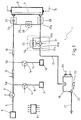
- Number 1 in Figure 1 indicates a dialysis unit, which is substantially defined by three parts: a first part in which the dialysis solution is prepared; a second part in which the dialysis solution is used; and a third part for draining the fluid from the second part and controlling the weight loss of the patient.
- the second part of unit 1 comprises a known dialyzer 3 in which a membrane 4 defines two channels, a first for extracorporeal blood flowing along a conduit 9, and a second for the dialysis fluid.
- the first part of unit 1 comprises:
- the third part of unit 1 comprises:
- Intercepting means 26, 27, 28 and 33 may be controlled manually and comprise, for example, straightforward grippers, or may be controlled electrically and comprise, for example, solenoid valves.
- Pump 31, branch 17d, conduit 32 and intercepting means 33 define an assembly 41, which provides for two different operating modes. More specifically, assembly 41 may permit flow along conduit 32 only, by cutting off branch 17d by means of pump 31 (as explained in detail later on), or may permit flow along branch 17d only by operating pump 31 and cutting off conduit 32.
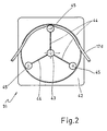
- Pump 31 of unit 1 in Figure 1 is a typical peristaltic pump and, as shown schematically in Figure 2, comprises an elongated hollow cylindrical body 42; a rotary shaft 43 rotated by an electric motor (not shown); three arms 44 extending radially from shaft 43 and spaced 120° apart; and idle wheels 45, each fitted to the free end of a respective arm 44.
- Shaft 43 is coaxial with body 42, which houses arms 44; the length of arms 44 and the diameter of wheels 45 are such that wheels 45 substantially contact the inner surface of body 42; and a portion of the inner surface of body 42 extending about an arc of over 120° houses a portion of conduit 17, so that, when pump 31 is turned off, at least one of wheels 45 presses on said conduit portion, cutting off all flow along conduit 17.
- wheels 45 naturally exert pressure successively along the whole of said portion of conduit 17, thus producing the known pumping effect.
- Number 51 in Figures 3 and 4 indicates a known pump, which may be fitted between points 17b and 17c of conduit 17 in place of assembly 41, and which, like assembly 41, provides for two different operating modes. More specifically, pump 51 is designed to permit free flow along branch 17d when disabled, and controlled flow along branch 17d when operated as a normal peristaltic pump.
- Pump 51 comprises an elongated body 52 formed from a cylindrical body (similar to body 42) from which is removed an axial portion extending in section about an angle of over 120°; a rotary shaft 53 rotated by an electric motor (not shown); three arms 54 extending radially from shaft 53 and spaced 120° apart; and idle wheels 55, each fitted to the free end of a respective arm 54.
- Shaft 53 is coaxial with body 52, which houses arms 54; and the length of arms 54 and the diameter of wheels 55 are such that wheels 55 substantially contact the inner surface of body 52.
- Pump 51 also comprises an elongated plate 56 extending in section about an arc of a radius equal to the inside radius of body 52. That is, plate 56 is so formed as to substantially define said portion removed from the cylindrical body from which body 52 is formed, and is movable, via actuating means 57, between a first position in which the inner surface of plate 56 is a continuation of the inner surface of body 52, and a second position in which the distance between the inner surface of plate 56 and the longitudinal axis of body 52 is greater than the inside radius of body 52.
- the inner surface of plate 56 houses a portion of conduit 17, so that, when pump 51 is turned off, at least one of wheels 55 presses on said conduit portion, cutting off all flow along conduit 17.
- wheels 55 naturally exert pressure successively along the whole of said portion of conduit 17, thus producing the known pumping effect.
- unit 1 also comprises an electronic central control unit 61 for controlling operation of unit 1, and more specifically all the peristaltic pumps, solenoid valve 22, and the intercepting means if these are electrically operated, and which is connected to sensors 15, 16 and means 23, 24.
- unit 61 for controlling operation of unit 1, and more specifically all the peristaltic pumps, solenoid valve 22, and the intercepting means if these are electrically operated, and which is connected to sensors 15, 16 and means 23, 24.
- the dialysis method substantially comprises two main operating cycles, the first of which provides for self-calibrating the flow of dialysis fluid along conduit 5 downstream from point 5b, and the second for determining and controlling the quantity of substances extracted from the blood at dialyzer 3, and hence the weight loss of the patient.
- the first cycle comprises:
- the second cycle comprises:
- Means 24 may be used in place of or in conjunction with means 23, so that flow into vessel 18 may be determined either by weighing (means 23) and/or by determining the level of the fluid fed in time into vessel 18. Means 24 may also be used to determine when a predetermined threshold level is exceeded, in which case, the fluid in vessel 18 is drained off by solenoid valve 22. Self-calibration of the pumps and control of the weight loss of the patient as described above may be performed repeatedly during treatment to control the weight loss of the patient more accurately and possibly also to adjust at various times during treatment both the dialysis solution flow and composition parameters and the desired weight loss.
- the unit provides for a unit and method enabling highly accurate control of the weight loss of the patient, by virtue of control not requiring detection of the functional characteristics of the peristaltic pumps to determine the flow rates involved.
- the method is fast and easy to implement, and may be performed repeatedly during treatment.
- the unit itself is straightforward in design, and requires no invasive flow detecting devices, and hence, no sterilization between one treatment and the next.
Applications Claiming Priority (2)
| Application Number | Priority Date | Filing Date | Title |
|---|---|---|---|
| IT96BO000150A IT1285624B1 (it) | 1996-03-18 | 1996-03-18 | Apparecchiatura per trattamenti di dialisi |
| ITBO960150 | 1996-03-18 |
Publications (2)
| Publication Number | Publication Date |
|---|---|
| EP0796998A1 true EP0796998A1 (fr) | 1997-09-24 |
| EP0796998B1 EP0796998B1 (fr) | 2003-05-21 |
Family
ID=11341265
Family Applications (1)
| Application Number | Title | Priority Date | Filing Date |
|---|---|---|---|
| EP97104549A Expired - Lifetime EP0796998B1 (fr) | 1996-03-18 | 1997-03-17 | Unite de Dialyse |
Country Status (5)
| Country | Link |
|---|---|
| EP (1) | EP0796998B1 (fr) |
| AT (1) | ATE240751T1 (fr) |
| DE (1) | DE69722065T2 (fr) |
| ES (1) | ES2200093T3 (fr) |
| IT (1) | IT1285624B1 (fr) |
Cited By (10)
| Publication number | Priority date | Publication date | Assignee | Title |
|---|---|---|---|---|
| EP2368582A3 (fr) * | 2003-11-05 | 2012-04-18 | Baxter International Inc. | Hémodialyse et systèmes d'hémofiltration |
| US8882692B2 (en) | 2003-11-05 | 2014-11-11 | Baxter International Inc. | Hemodialysis system with multiple cassette interference |
| US9095661B2 (en) | 2009-12-22 | 2015-08-04 | Gambro Lundia Ab | Method and apparatus for controlling a fluid flow rate in a fluid transport line of a medical device |
| CN105903095A (zh) * | 2015-02-25 | 2016-08-31 | B·布莱恩·阿维图姆股份公司 | 整合在壳体正面中的血泵 |
| US9697334B2 (en) | 2008-07-09 | 2017-07-04 | Baxter International Inc. | Dialysis system having approved therapy prescriptions presented for selection |
| US9764074B1 (en) | 2002-07-19 | 2017-09-19 | Baxter International Inc. | Systems and methods for performing dialysis |
| US9925320B2 (en) | 2007-10-24 | 2018-03-27 | Baxter International Inc. | Renal therapy machine and system including a priming sequence |
| EP3238761A4 (fr) * | 2014-12-25 | 2018-06-06 | Asahi Kasei Medical Europe GmbH | Système de traitement du sang |
| US10232103B1 (en) | 2001-11-13 | 2019-03-19 | Baxter International Inc. | System, method, and composition for removing uremic toxins in dialysis processes |
| EP1699505B2 (fr) † | 2003-12-16 | 2022-08-03 | Baxter International Inc. | Systemes de controle de flux de therapie fluidique medicale |
Families Citing this family (3)
| Publication number | Priority date | Publication date | Assignee | Title |
|---|---|---|---|---|
| US8803044B2 (en) | 2003-11-05 | 2014-08-12 | Baxter International Inc. | Dialysis fluid heating systems |
| WO2023174604A1 (fr) * | 2022-03-16 | 2023-09-21 | Gambro Lundia Ab | Génération de fluide médical pour thérapie de remplacement rénal |
| WO2023237358A1 (fr) * | 2022-06-09 | 2023-12-14 | Shl Medical Ag | Ensemble d'entraînement pour dispositif de distribution de médicament |
Citations (7)
| Publication number | Priority date | Publication date | Assignee | Title |
|---|---|---|---|---|
| US3878095A (en) * | 1974-05-02 | 1975-04-15 | Advanced Medical Sciences Inc | Dialysis apparatus |
| US4137168A (en) * | 1976-10-02 | 1979-01-30 | Klauschenz & Perrot Kg | Device for dialysation of blood |
| US4769132A (en) * | 1985-06-07 | 1988-09-06 | Miren S.R.L. | Device for controlling the water balance of patients undergoing haemodialysis |
| US4889635A (en) * | 1986-04-25 | 1989-12-26 | Hospal Industrie | Method and apparatus for controlling the quantities of liquid circulating in the dialysis liquid circuit of an artificial kidney |
| EP0403401A1 (fr) * | 1989-05-29 | 1990-12-19 | Hospal Industrie | Méthode de contrôle de l'ultrafiltration et dispositif pour sa mise en oeuvre |
| US5052900A (en) * | 1990-04-11 | 1991-10-01 | Austin Jon W | Pressure relief valve for positive pressure pumps |
| EP0678301A2 (fr) * | 1991-09-10 | 1995-10-25 | Hospal Industrie | Appareil multifonction pour le traitement de l'insuffisance rénale |
-
1996
- 1996-03-18 IT IT96BO000150A patent/IT1285624B1/it active IP Right Grant
-
1997
- 1997-03-17 DE DE69722065T patent/DE69722065T2/de not_active Expired - Fee Related
- 1997-03-17 AT AT97104549T patent/ATE240751T1/de not_active IP Right Cessation
- 1997-03-17 EP EP97104549A patent/EP0796998B1/fr not_active Expired - Lifetime
- 1997-03-17 ES ES97104549T patent/ES2200093T3/es not_active Expired - Lifetime
Patent Citations (7)
| Publication number | Priority date | Publication date | Assignee | Title |
|---|---|---|---|---|
| US3878095A (en) * | 1974-05-02 | 1975-04-15 | Advanced Medical Sciences Inc | Dialysis apparatus |
| US4137168A (en) * | 1976-10-02 | 1979-01-30 | Klauschenz & Perrot Kg | Device for dialysation of blood |
| US4769132A (en) * | 1985-06-07 | 1988-09-06 | Miren S.R.L. | Device for controlling the water balance of patients undergoing haemodialysis |
| US4889635A (en) * | 1986-04-25 | 1989-12-26 | Hospal Industrie | Method and apparatus for controlling the quantities of liquid circulating in the dialysis liquid circuit of an artificial kidney |
| EP0403401A1 (fr) * | 1989-05-29 | 1990-12-19 | Hospal Industrie | Méthode de contrôle de l'ultrafiltration et dispositif pour sa mise en oeuvre |
| US5052900A (en) * | 1990-04-11 | 1991-10-01 | Austin Jon W | Pressure relief valve for positive pressure pumps |
| EP0678301A2 (fr) * | 1991-09-10 | 1995-10-25 | Hospal Industrie | Appareil multifonction pour le traitement de l'insuffisance rénale |
Cited By (32)
| Publication number | Priority date | Publication date | Assignee | Title |
|---|---|---|---|---|
| US10980931B2 (en) | 2001-11-13 | 2021-04-20 | Baxter International Inc. | System, method, and composition for removing uremic toxins in dialysis processes |
| US10232103B1 (en) | 2001-11-13 | 2019-03-19 | Baxter International Inc. | System, method, and composition for removing uremic toxins in dialysis processes |
| US9764074B1 (en) | 2002-07-19 | 2017-09-19 | Baxter International Inc. | Systems and methods for performing dialysis |
| US10245369B2 (en) | 2003-11-05 | 2019-04-02 | Baxter International Inc. | Systems and methods for priming hemodialysis using dialysis fluid |
| US9072843B2 (en) | 2003-11-05 | 2015-07-07 | Baxter International Inc. | Renal therapy system having pump reversing fluid control |
| US9889243B2 (en) | 2003-11-05 | 2018-02-13 | Baxter International Inc. | Dialysis system including automatic priming |
| US9050411B2 (en) | 2003-11-05 | 2015-06-09 | Baxter International Inc. | Dialysis system including downloaded prescription entry |
| US8882692B2 (en) | 2003-11-05 | 2014-11-11 | Baxter International Inc. | Hemodialysis system with multiple cassette interference |
| US10426883B2 (en) | 2003-11-05 | 2019-10-01 | Baxter International Inc. | Systems and methods for priming hemodialysis using multiple fluid sources |
| US9144641B2 (en) | 2003-11-05 | 2015-09-29 | Baxter International Inc. | Dialysis system with balance chamber prime and rinseback |
| US10293096B2 (en) | 2003-11-05 | 2019-05-21 | Baxter International Inc. | Dialysis system including cassette with pumping tubes |
| US9642961B2 (en) | 2003-11-05 | 2017-05-09 | Baxter International Inc. | Renal failure therapy machines and methods including convective and diffusive clearance |
| US9675745B2 (en) | 2003-11-05 | 2017-06-13 | Baxter International Inc. | Dialysis systems including therapy prescription entries |
| EP2368582A3 (fr) * | 2003-11-05 | 2012-04-18 | Baxter International Inc. | Hémodialyse et systèmes d'hémofiltration |
| US10245370B2 (en) | 2003-11-05 | 2019-04-02 | Baxter International Inc. | Renal failure therapy machines and methods including convective and diffusive clearance |
| US9872950B2 (en) | 2003-11-05 | 2018-01-23 | Baxter International Inc. | Renal therapy system having pump reversing fluid control |
| US9884144B2 (en) | 2003-11-05 | 2018-02-06 | Baxter International Inc. | Hemodialysis system with cassette-based blood and dialysate pumping |
| US9039648B2 (en) | 2003-11-05 | 2015-05-26 | Baxter International Inc. | Dialysis system with enhanced features |
| US9028436B2 (en) | 2003-11-05 | 2015-05-12 | Baxter International Inc. | Hemodialysis system with cassette-based blood and dialyste pumping |
| US9005152B2 (en) | 2003-11-05 | 2015-04-14 | Baxter International Inc. | Dialysis system with cassette based balance chambers and volumetric pumps |
| US10155080B2 (en) | 2003-11-05 | 2018-12-18 | Baxter International Inc. | Renal therapy system with cassette-based blood and dialysate pumping |
| US10183109B2 (en) | 2003-11-05 | 2019-01-22 | Baxter International Inc. | Hemodialysis system including a disposable cassette |
| US8926540B2 (en) | 2003-11-05 | 2015-01-06 | Baxter Healthcare Inc. | Hemodialysis system with separate dialysate cassette |
| EP1699505B2 (fr) † | 2003-12-16 | 2022-08-03 | Baxter International Inc. | Systemes de controle de flux de therapie fluidique medicale |
| US10695479B2 (en) | 2007-10-24 | 2020-06-30 | Baxter International Inc. | Renal therapy machine and method including a priming sequence |
| US9925320B2 (en) | 2007-10-24 | 2018-03-27 | Baxter International Inc. | Renal therapy machine and system including a priming sequence |
| US11291752B2 (en) | 2007-10-24 | 2022-04-05 | Baxter International Inc. | Hemodialysis system including a disposable set and a dialysis instrument |
| US9697334B2 (en) | 2008-07-09 | 2017-07-04 | Baxter International Inc. | Dialysis system having approved therapy prescriptions presented for selection |
| US9095661B2 (en) | 2009-12-22 | 2015-08-04 | Gambro Lundia Ab | Method and apparatus for controlling a fluid flow rate in a fluid transport line of a medical device |
| EP3238761A4 (fr) * | 2014-12-25 | 2018-06-06 | Asahi Kasei Medical Europe GmbH | Système de traitement du sang |
| CN105903095A (zh) * | 2015-02-25 | 2016-08-31 | B·布莱恩·阿维图姆股份公司 | 整合在壳体正面中的血泵 |
| CN105903095B (zh) * | 2015-02-25 | 2020-12-11 | B·布莱恩·阿维图姆股份公司 | 整合在壳体正面中的血泵 |
Also Published As
| Publication number | Publication date |
|---|---|
| ITBO960150A0 (it) | 1996-03-18 |
| DE69722065T2 (de) | 2004-04-08 |
| EP0796998B1 (fr) | 2003-05-21 |
| ATE240751T1 (de) | 2003-06-15 |
| IT1285624B1 (it) | 1998-06-18 |
| DE69722065D1 (de) | 2003-06-26 |
| ITBO960150A1 (it) | 1997-09-18 |
| ES2200093T3 (es) | 2004-03-01 |
Similar Documents
| Publication | Publication Date | Title |
|---|---|---|
| EP0796998B1 (fr) | Unite de Dialyse | |
| EP0796997A1 (fr) | Unité de dialyse | |
| US20210340968A1 (en) | Device for extracorporeal blood treatment | |
| EP0745400B1 (fr) | Réglage automatique de l'occlusion d'une pompe péristaltique | |
| EP1434646B2 (fr) | Dispositif de commande d'un appareil de dialyse | |
| CA2784205C (fr) | Dispositif d'equilibrage, dispositif fonctionnel medical externe, dispositif de traitement et procedes correspondants | |
| JPH01119262A (ja) | 血液を透析し、限外濾液を抜き出す装置 | |
| RU2759193C1 (ru) | Высокоточная система управления расходом перистальтического насоса | |
| EP3034106B1 (fr) | Systèmes et procédés d'étalonnage de volumes de course de pompe pendant une procédure de séparation du sang | |
| WO2019142925A1 (fr) | Dispositif de réglage de détecteur de pression | |
| JP5873859B2 (ja) | 少なくとも1つの濾過値の制御のための装置、血液透析装置、並びにそのための方法及びその使用 | |
| JP2912801B2 (ja) | 血液透析装置 | |
| US4458877A (en) | Flushing apparatus | |
| CA1142449A (fr) | Regulateur de rythme d'ultrafiltration | |
| EP0824021B1 (fr) | Unité de dialyse | |
| EP0911042A1 (fr) | Dispositif pour traitement par dialyse | |
| JPH02239870A (ja) | 血液透析装置の除水量制御装置 | |
| CN116367880A (zh) | 阀装置、流出物袋和方法 | |
| JPS649866B2 (fr) | ||
| JPS60156471A (ja) | 人工透析装置 | |
| JPH0212111B2 (fr) | ||
| JPH0356740B2 (fr) | ||
| CS267871B3 (cs) | Zařízení pro řízenou ultrafiltraci,zejména při dialýze |
Legal Events
| Date | Code | Title | Description |
|---|---|---|---|
| PUAI | Public reference made under article 153(3) epc to a published international application that has entered the european phase |
Free format text: ORIGINAL CODE: 0009012 |
|
| AK | Designated contracting states |
Kind code of ref document: A1 Designated state(s): AT BE CH DE ES FR GB GR LI NL SE |
|
| 17P | Request for examination filed |
Effective date: 19980319 |
|
| 17Q | First examination report despatched |
Effective date: 20011016 |
|
| GRAH | Despatch of communication of intention to grant a patent |
Free format text: ORIGINAL CODE: EPIDOS IGRA |
|
| RIC1 | Information provided on ipc code assigned before grant |
Free format text: 7A 61M 1/16 A, 7F 04B 43/12 B |
|
| RIC1 | Information provided on ipc code assigned before grant |
Free format text: 7A 61M 1/16 A, 7F 04B 43/12 B |
|
| RIC1 | Information provided on ipc code assigned before grant |
Free format text: 7A 61M 1/16 A, 7F 04B 43/12 B |
|
| GRAH | Despatch of communication of intention to grant a patent |
Free format text: ORIGINAL CODE: EPIDOS IGRA |
|
| GRAA | (expected) grant |
Free format text: ORIGINAL CODE: 0009210 |
|
| RAP1 | Party data changed (applicant data changed or rights of an application transferred) |
Owner name: BELLCO S.P.A. |
|
| AK | Designated contracting states |
Designated state(s): AT BE CH DE ES FR GB GR LI NL SE |
|
| REG | Reference to a national code |
Ref country code: GB Ref legal event code: FG4D |
|
| REG | Reference to a national code |
Ref country code: CH Ref legal event code: EP |
|
| REF | Corresponds to: |
Ref document number: 69722065 Country of ref document: DE Date of ref document: 20030626 Kind code of ref document: P |
|
| REG | Reference to a national code |
Ref country code: SE Ref legal event code: TRGR |
|
| REG | Reference to a national code |
Ref country code: GR Ref legal event code: EP Ref document number: 20030403157 Country of ref document: GR |
|
| REG | Reference to a national code |
Ref country code: CH Ref legal event code: NV Representative=s name: NOVAGRAAF INTERNATIONAL SA |
|
| REG | Reference to a national code |
Ref country code: ES Ref legal event code: FG2A Ref document number: 2200093 Country of ref document: ES Kind code of ref document: T3 |
|
| PLBE | No opposition filed within time limit |
Free format text: ORIGINAL CODE: 0009261 |
|
| STAA | Information on the status of an ep patent application or granted ep patent |
Free format text: STATUS: NO OPPOSITION FILED WITHIN TIME LIMIT |
|
| ET | Fr: translation filed | ||
| 26N | No opposition filed |
Effective date: 20040224 |
|
| REG | Reference to a national code |
Ref country code: CH Ref legal event code: PCAR Free format text: NOVAGRAAF INTERNATIONAL SA;25, AVENUE DU PAILLY;1220 LES AVANCHETS (CH) |
|
| PGFP | Annual fee paid to national office [announced via postgrant information from national office to epo] |
Ref country code: DE Payment date: 20090313 Year of fee payment: 13 |
|
| PGFP | Annual fee paid to national office [announced via postgrant information from national office to epo] |
Ref country code: CH Payment date: 20100323 Year of fee payment: 14 |
|
| PGFP | Annual fee paid to national office [announced via postgrant information from national office to epo] |
Ref country code: GB Payment date: 20100317 Year of fee payment: 14 Ref country code: AT Payment date: 20100312 Year of fee payment: 14 |
|
| PGFP | Annual fee paid to national office [announced via postgrant information from national office to epo] |
Ref country code: NL Payment date: 20100304 Year of fee payment: 14 |
|
| PG25 | Lapsed in a contracting state [announced via postgrant information from national office to epo] |
Ref country code: DE Free format text: LAPSE BECAUSE OF NON-PAYMENT OF DUE FEES Effective date: 20101001 |
|
| REG | Reference to a national code |
Ref country code: CH Ref legal event code: PFA Owner name: BELLCO S.P.A. Free format text: BELLCO S.P.A.#VIA BORGONUOVO, 14#20121 MILANO (IT) -TRANSFER TO- BELLCO S.P.A.#VIA BORGONUOVO, 14#20121 MILANO (IT) |
|
| REG | Reference to a national code |
Ref country code: NL Ref legal event code: V1 Effective date: 20111001 |
|
| REG | Reference to a national code |
Ref country code: CH Ref legal event code: PL |
|
| GBPC | Gb: european patent ceased through non-payment of renewal fee |
Effective date: 20110317 |
|
| PG25 | Lapsed in a contracting state [announced via postgrant information from national office to epo] |
Ref country code: AT Free format text: LAPSE BECAUSE OF NON-PAYMENT OF DUE FEES Effective date: 20110317 |
|
| PG25 | Lapsed in a contracting state [announced via postgrant information from national office to epo] |
Ref country code: CH Free format text: LAPSE BECAUSE OF NON-PAYMENT OF DUE FEES Effective date: 20110331 Ref country code: LI Free format text: LAPSE BECAUSE OF NON-PAYMENT OF DUE FEES Effective date: 20110331 Ref country code: NL Free format text: LAPSE BECAUSE OF NON-PAYMENT OF DUE FEES Effective date: 20111001 |
|
| PG25 | Lapsed in a contracting state [announced via postgrant information from national office to epo] |
Ref country code: GB Free format text: LAPSE BECAUSE OF NON-PAYMENT OF DUE FEES Effective date: 20110317 |
|
| PGFP | Annual fee paid to national office [announced via postgrant information from national office to epo] |
Ref country code: GR Payment date: 20130319 Year of fee payment: 17 |
|
| PGFP | Annual fee paid to national office [announced via postgrant information from national office to epo] |
Ref country code: SE Payment date: 20140311 Year of fee payment: 18 |
|
| PGFP | Annual fee paid to national office [announced via postgrant information from national office to epo] |
Ref country code: FR Payment date: 20140311 Year of fee payment: 18 |
|
| PGFP | Annual fee paid to national office [announced via postgrant information from national office to epo] |
Ref country code: BE Payment date: 20140312 Year of fee payment: 18 |
|
| PGFP | Annual fee paid to national office [announced via postgrant information from national office to epo] |
Ref country code: ES Payment date: 20140227 Year of fee payment: 18 |
|
| REG | Reference to a national code |
Ref country code: GR Ref legal event code: ML Ref document number: 20030403157 Country of ref document: GR Effective date: 20141002 |
|
| PG25 | Lapsed in a contracting state [announced via postgrant information from national office to epo] |
Ref country code: GR Free format text: LAPSE BECAUSE OF NON-PAYMENT OF DUE FEES Effective date: 20141002 |
|
| PG25 | Lapsed in a contracting state [announced via postgrant information from national office to epo] |
Ref country code: SE Free format text: LAPSE BECAUSE OF NON-PAYMENT OF DUE FEES Effective date: 20150318 |
|
| REG | Reference to a national code |
Ref country code: SE Ref legal event code: EUG |
|
| REG | Reference to a national code |
Ref country code: FR Ref legal event code: ST Effective date: 20151130 |
|
| PG25 | Lapsed in a contracting state [announced via postgrant information from national office to epo] |
Ref country code: FR Free format text: LAPSE BECAUSE OF NON-PAYMENT OF DUE FEES Effective date: 20150331 |
|
| REG | Reference to a national code |
Ref country code: ES Ref legal event code: FD2A Effective date: 20160426 |
|
| PG25 | Lapsed in a contracting state [announced via postgrant information from national office to epo] |
Ref country code: ES Free format text: LAPSE BECAUSE OF NON-PAYMENT OF DUE FEES Effective date: 20150318 |
|
| PG25 | Lapsed in a contracting state [announced via postgrant information from national office to epo] |
Ref country code: BE Free format text: LAPSE BECAUSE OF NON-PAYMENT OF DUE FEES Effective date: 20150331 |