EP0796823A2 - Verfahren und Vorrichtung zur Zuführung von Abfallstoffen in einen Heizkessel - Google Patents
Verfahren und Vorrichtung zur Zuführung von Abfallstoffen in einen Heizkessel Download PDFInfo
- Publication number
- EP0796823A2 EP0796823A2 EP97104713A EP97104713A EP0796823A2 EP 0796823 A2 EP0796823 A2 EP 0796823A2 EP 97104713 A EP97104713 A EP 97104713A EP 97104713 A EP97104713 A EP 97104713A EP 0796823 A2 EP0796823 A2 EP 0796823A2
- Authority
- EP
- European Patent Office
- Prior art keywords
- slurry
- waste
- hydrothermal reaction
- subjected
- boiler
- Prior art date
- Legal status (The legal status is an assumption and is not a legal conclusion. Google has not performed a legal analysis and makes no representation as to the accuracy of the status listed.)
- Withdrawn
Links
Images
Classifications
-
- C—CHEMISTRY; METALLURGY
- C02—TREATMENT OF WATER, WASTE WATER, SEWAGE, OR SLUDGE
- C02F—TREATMENT OF WATER, WASTE WATER, SEWAGE, OR SLUDGE
- C02F11/00—Treatment of sludge; Devices therefor
- C02F11/18—Treatment of sludge; Devices therefor by thermal conditioning
-
- B—PERFORMING OPERATIONS; TRANSPORTING
- B09—DISPOSAL OF SOLID WASTE; RECLAMATION OF CONTAMINATED SOIL
- B09B—DISPOSAL OF SOLID WASTE NOT OTHERWISE PROVIDED FOR
- B09B3/00—Destroying solid waste or transforming solid waste into something useful or harmless
- B09B3/30—Destroying solid waste or transforming solid waste into something useful or harmless involving mechanical treatment
- B09B3/35—Shredding, crushing or cutting
-
- B—PERFORMING OPERATIONS; TRANSPORTING
- B09—DISPOSAL OF SOLID WASTE; RECLAMATION OF CONTAMINATED SOIL
- B09B—DISPOSAL OF SOLID WASTE NOT OTHERWISE PROVIDED FOR
- B09B3/00—Destroying solid waste or transforming solid waste into something useful or harmless
- B09B3/70—Chemical treatment, e.g. pH adjustment or oxidation
-
- B—PERFORMING OPERATIONS; TRANSPORTING
- B09—DISPOSAL OF SOLID WASTE; RECLAMATION OF CONTAMINATED SOIL
- B09C—RECLAMATION OF CONTAMINATED SOIL
- B09C1/00—Reclamation of contaminated soil
- B09C1/06—Reclamation of contaminated soil thermally
-
- C—CHEMISTRY; METALLURGY
- C02—TREATMENT OF WATER, WASTE WATER, SEWAGE, OR SLUDGE
- C02F—TREATMENT OF WATER, WASTE WATER, SEWAGE, OR SLUDGE
- C02F11/00—Treatment of sludge; Devices therefor
- C02F11/10—Treatment of sludge; Devices therefor by pyrolysis
-
- Y—GENERAL TAGGING OF NEW TECHNOLOGICAL DEVELOPMENTS; GENERAL TAGGING OF CROSS-SECTIONAL TECHNOLOGIES SPANNING OVER SEVERAL SECTIONS OF THE IPC; TECHNICAL SUBJECTS COVERED BY FORMER USPC CROSS-REFERENCE ART COLLECTIONS [XRACs] AND DIGESTS
- Y02—TECHNOLOGIES OR APPLICATIONS FOR MITIGATION OR ADAPTATION AGAINST CLIMATE CHANGE
- Y02W—CLIMATE CHANGE MITIGATION TECHNOLOGIES RELATED TO WASTEWATER TREATMENT OR WASTE MANAGEMENT
- Y02W10/00—Technologies for wastewater treatment
- Y02W10/40—Valorisation of by-products of wastewater, sewage or sludge processing
-
- Y—GENERAL TAGGING OF NEW TECHNOLOGICAL DEVELOPMENTS; GENERAL TAGGING OF CROSS-SECTIONAL TECHNOLOGIES SPANNING OVER SEVERAL SECTIONS OF THE IPC; TECHNICAL SUBJECTS COVERED BY FORMER USPC CROSS-REFERENCE ART COLLECTIONS [XRACs] AND DIGESTS
- Y10—TECHNICAL SUBJECTS COVERED BY FORMER USPC
- Y10S—TECHNICAL SUBJECTS COVERED BY FORMER USPC CROSS-REFERENCE ART COLLECTIONS [XRACs] AND DIGESTS
- Y10S210/00—Liquid purification or separation
- Y10S210/918—Miscellaneous specific techniques
- Y10S210/919—Miscellaneous specific techniques using combined systems by merging parallel diverse waste systems
Definitions
- This invention relates to a method of feeding wastes into a boiler, more particularly, to a method of heat treatment by which municipal wastes, night soil, sewage sludge, industrial wastes and other forms of wastes that contain organic matter are converted into a fuel in the presence of water such that it can be fed into a boiler, as well as a method by which high-moisture wastes containing halogens can be converted into a fuel for supply into a boiler.
- a solids-containing waste is finely divided and converted into a slurry, from which inorganics such as glass, tiles and pebbles, metals, etc. are removed as much as possible. If the waste is already of a fine size and need not be ground or if it is substantially free of solids as in the case of sludge or liquid waste, it may optionally be passed through a screen to remove coarse solids. Then, the slurry is pressurized, heated to a suitable temperature between 250°C and 350°C depending upon waste type and held at that temperature typically for several tens of minutes in order to cause a hydrothermal reaction. As a result, the organic matter in the waste is dehalogenated and/or decarbonated such that it is converted to carbides (generally called "char"), pitch or tar-like oil, from which the aqueous phase is removed to form a fuel.
- char carbides
- the slurry to be pressurized is mixed with a sufficient amount of alkali that the slurry remains alkaline and will not become acidic even if it is subjected to a hydrothermal reaction.
- This alkali addition is performed in order to increase the yield of the oil as the reaction product and examples of the alkali commonly added include Na 2 CO 3 , NaOH and Ca(OH) 2 . If hydrochloric acid or other strong acids occur during the reaction, the pH of the slurry decreases so much that those parts of the reactor, heat exchangers, pipes and other system components which are in contact with the liquid will be attacked by severe corrosion and alkalies are added in order to prevent this problem.
- the effluent resulting from the removal of the aqueous phase has very high BOD and COD levels (> several tens of thousand ppm) and cannot be treated easily.
- the waste contains alkaline earth metal elements such as calcium and magnesium, the latter will enter into a precipitation reaction with the sulfur oxides and carbonic acid that have occurred in the hydrothermal reaction, causing scale deposition on the surfaces of those areas of the reactor, heat exchangers, pipes and other system components which are in contact with the liquid; the scale will gradually grow until the system operation is no longer possible.
- alkaline earth metal elements such as calcium and magnesium
- the present invention has been accomplished under these circumstances and has as an object providing a method by which wastes can be supplied as a mass of high heat value into a boiler in such a manner that the organic matter is transferred by a smaller amount into the aqueous phase during a hydrothermal reaction and that there is no scale deposit on the surfaces of those areas of the system components in contact with the liquid.
- This object can be attained by a method for feeding a waste containing organic solids into a boiler after it has been subjected to a hydrothermal reaction treatment in the presence of water, which method comprises the steps of holding a slurry containing said waste under a high-temperature and high-pressure condition to cause a hydrothermal reaction such that an acidic slurry is formed during part of or throughout the process of said hydrothermal reaction, thereby reducing the content of oxygen in said waste relative to the carbon atoms in the building molecule of said waste, concurrently causing any halogens in said building molecule to be transferred into said slurry, then cooling said slurry, dewatering the cooled slurry and feeding the dewatered slurry into the combustion section of the boiler.
- an apparatus for feeding a wasste containing organic solids into a boiler comprising a grinder for reducing the size of the waste in water, a filter with which an aqueous suspension of the ground waste as taken out of said grinder is freed of a certain amount of water so as to make a slurry of the waste, a storage tank for storing said waste slurry temporarily before it is subjected to a hydrothermal reaction, a reactor in which the slurry as taken out of said storage tank is subjected to a hydrothermal reaction under a high-temperature and high-pressure condition, a cooler for cooling the waste slurry which has been subjected to the hydrothermal reaction, a filter for dewatering said cooled waste slurry, and a conveyor for feeding the boiler with a fuel composed of the dewatered waste slurry.
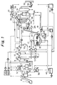
- Fig 1 is a diagram showing the general scheme for supplying a waste into a boiler according to the method of the invention.
- the oil content is mostly made of pitch-like solids at ordinary temperature. Therefore, by changing the nature of the slurry from alkalinity to acidity, the yield of the feed to boiler that can be obtained by removing the aqueous phase from the slurry after the reaction is increased to a much higher level than has been possible in the prior art and the BOD and COD levels in the removed aqueous phase are reduced markedly.
- the slurry was in the form of a cololoid because the oxygen atoms and hydroxyl groups in the molecule contributed to attract the molecules of water; however, such a molecular structure is disrupted during the reaction, thereby transforming the slurry to a form of extremely high settleability, namely, a slurry that can be dewatered most efficiently. Further improvements in settleability and dewatering property can be accomplished by adjusting the slurry to weak alkalinity in the range of pH 8 - 9 after the reaction.
- Any halogens that are contained in compounds in the waste start to leave them at temperatures of about 250°C.
- the leaving reaction will not proceed smoothly in an oxidizing atmosphere but in the method of the present invention which does not involve oxygen blowing, a strong reducing atmosphere predominates to provide a favorable condition for the progress of a dehalogenation reaction.
- the hydrothermal reaction is diverse and the pH also changes in various ways during the reaction depending upon the type of the feed to be treated.
- a waste slurry that contains a halogen compound such as poly (vinyl chloride)
- the halogen is transferred into the aqueous phase to be ionized, causing a marked drop in pH.
- the pH will increase due to the formation of ammonium ions and amino groups.
- the ideal operation is such that the waste to be treated is sorted into two types for storage, one which will experience a drop in pH as the result of the hydrothermal reaction and the other which will experience an increase in pH, and the two types of waste are subjected to the hydrothermal reaction as they are mixed in a ratio that is varied in accordance with the desired pH of the reaction products such that the pH of the waste slurry is maintained in a weakly acidic condition (pH ca. 3 - 5) throughout the progress of the hydrothermal reaction. At a pH above 6, the effectiveness of allowing the reaction to proceed under an acidic condition is reduced.
- the reaction products are acidic enough to prevent the precipitation of sulfates or carbonates of alkaline earth metal elements such as calcium and magnesium and, hence, there is little formation of scale which has been a problem in the prior art.
- the acidic nature of the waste slurry also has the advantage of causing most of the salts in the waste to dissolve in the aqueous phase.
- substantial portions of heavy metals such as Pb, Cd, Zn and As will be transferred into the aqueous phase under the acidic condition of the waste slurry.
- the organic matter in the waste selectively releases oxygen from its building molecule to turn into friable carbides some of which have a higher degree of carbonization.
- the reaction products are preferably burnt in a boiler having a fluidized bed or divided into a fine size in a liquid to form a coal-oil mixture (COM) or a coal-water mixture (CWM) which are subsequently stored, transported or burnt.
- COM coal-oil mixture
- CWM coal-water mixture
- Fig 1 shows the general scheme for the method of supplying a waste into a boiler by the method of the invention.
- a waste 1 containing organic solids is transported on a charging conveyor 2 to be charged into a wet grinder 3.
- the conveyor speed is adjusted such that the waste 1 is charged to ensure that an aqueous suspension in the wet grinder 3 will contain the ground waste at a concentration that is as constant as possible.
- the waste is ground into fine particles of a few millimeters in the wet grinder 3, from which they emerge and enter a foreign matter separator 4, where sand and metals are separated by inertia.
- the waste slurry is supplied onto a coarse belt filter 5 with an appropriate setting of the distance between the filter head and the position in which the waste slurry is supplied.
- the waste slurry is adjusted to an appropriate water content as it is transported on the belt filter 5.
- the adjusted water content should be within such a range that there will be no problem with the handling of the slurry.
- the slurry is stored in tanks 6.
- the filtrate from the belt filter 5 will flow back into the wet grinder 3.
- part of the aqueous suspension of the ground waste emerging from the foreign matter separator 4 is returned into the wet grinder 3 so as to prevent the drop in the rate of the slurry flowing through the separator 4, thereby ensuring that the latter will exhibit the intended performance in inertial separation.
- the tanks 6 consist of an alkali tank 6a for storing the waste slurry the pH of which will increase as the result of the hydrothermal reaction and an acid tank 6b for storing the slurry the pH of which will decrease during the hydrothermal reaction. Selection between the two tanks is made by means of a switching chute 7 such that the slurry originating from a waste of high contents of proteins and garbage is retained in the alkali tank 6a whereas the slurry originating from a waste of high content of scrap plastics is retained in the acid tank 6b.
- the waste slurry in the tanks 6 is pressurized to about 170 atmospheres by means of a high-pressure pump 8 and passed through successive heat exchangers 9, 10 and 11; in the heat exchanger 9, the slurry is subjected to heat exchange with flash vapor; in the next heat exchanger 10, the slurry is subjected to heat exchange with the waste slurry that has undergone the hydrothermal reaction; in the final heat exchanger 11, the slurry is subjected to heat exchange with the heating medium so that it is heated to a temperature of about 325°C.
- the thus heated slurry is then fed into a hydrothermal reactor 12, where it is held at the same temperature for several tens of minutes.
- the liquid pressure in the reactor 12 is held higher than the vapor pressure at the retained temperature so as to prevent the slurry from boiling.
- the temperature of the heating medium is controlled to be such that the temperature of the waste slurry within the reactor 12 will reach a predetermined setting.
- the opening of the valves on the tanks 6a and 6b through which the respective types of waste slurry are supplied are adjusted in such a way that the pH of the slurry at the exit of the reactor 12 will be in the weak acidic range of 3 - 5. If the control of the valve openings is not completely effective or in the case where the tank of the slurry which need be supplied in order to adjust the pH to be within the stated range has become empty, hydrochloric acid or sodium hydroxide shall be injected into the slurry emerging from that tank. Before performing degassing and cooling in a flash tank 13 to be described in the next paragraph, sodium hydroxide is injected into the waste slurry that has been subjected to the hydrothermal reaction, thereby adjusting the pH of the slurry to about 8. At least in the case of performing cooling within the heat exchanger 10, the pH of the waste slurry should be adjusted to be within the weak acidic range of about 3 - 5 so as to prevent scaling in the high-temperature and high-pressure areas.
- the waste slurry is returned to the heat exchanger 10, where it is subjected to heat exchange with the slurry which is yet to be subjected to the reaction; the slurry then leaves the heat exchanger 10 to enter the flash tank 13, where it is rapidly depressurized to cause evaporation of water and simultaneous cooling, whereupon gases such as nitrogen, carbon dioxide, methylmercaptan hydrogen sulfide which are contained in the waste are separated together with the vapor which has been generated as the result of depressurization.
- gases such as nitrogen, carbon dioxide, methylmercaptan hydrogen sulfide which are contained in the waste are separated together with the vapor which has been generated as the result of depressurization.
- This step may be a single-stage or a multiple-stage step, in which a plurality of heat exchangers 9 for performing heat exchange between the waste slurry to be subjected to the reaction and the flash vapor are respectively combined with a corresponding number of flash tanks 13 for flashing the waste slurry that has been subjected to the reaction and the individual combinations are connected in series to ensure that degassing is performed more thoroughly and that the waste slurry to be subjected to the reaction will be heated to an even higher temperature by means of the flash vapor. It should be noted that since the waste slurry which has been subjected to the reaction was already neutralized to weak alkalinity before it was flashed, the flash vapor will not contain hydrochloric acid but may occasionally contain ammonia gas.
- the waste slurry that has been cooled to 100°C by flashing after the reaction then enters a heat exchanger 14, where it is further cooled by heat exchange with the boiler feedwater.
- the cooled slurry is passed through a belt filter 15 to have the aqueous phase squeezed off and washed with the water formed by condensing the flash vapor with the boiler feedwater in a heat exchanger 16 and which has been separated from the vapor by means of a gas-liquid separator 17; the washed slurry is dewatered again by means of the belt filter 15.
- the aqueous phase squeezed off the slurry is fed into a drum-type dryer 18, where it is evaporated to dryness with a vapor to turn into a salt.
- the exhaust from the dryer 18 is supplied to a cooler 19, where it is cooled with the boiler feedwater to yield drain water, which is collected in a tank 20 for subsequent use on the belt filter 15 to wash the waste slurry which has been subjected to the reaction, as well as to wash the foreign matter that will be removed in a foreign matter separator 39.
- a liquid waste 40 that results from the final washing is returned to the wet grinder 3.
- the oil content resulting from dewatering with the belt filter 15 is smaller in quantity than the solid phase including char and mostly composed of a heavy fraction which will solidify into a pitch-like mass at a temperature below 30 - 50°C; hence, upon cooling, the oil content is accompanied by the solid phase through adsorption and can be easily separated from the aqueous phase together with the solid phase.
- a raw fuel composed of the resulting oil-containing solid phase is transported by a boiler charging conveyor 21 and dumped into a feeder hopper 22, from which it is passed through a feeder 23 to be charged into a fluidized bed 24 for combustion.
- the cooled exhaust gas in the flash vapor, the cooled exhaust gas from the drum-type dryer 18 and the ventilation from the wet grinder 3 are supplied as boiler combustion air into a boiler 26 via a forced-draft fan 25, whereby any odor-producing components will be decomposed by oxidation.
- a tube 27 for heating the heating medium is inserted into the furnace in the boiler and by controlling the rate at which the heating medium to be subjected to heat exchange with the boiler feedwater in the heat exchanger 35 will flow through said heat exchanger, the radiation of heat from the heating medium is controlled so as to adjust its temperature.
- the exhaust combustion gas from the fluidized bed 24 is heat recovered by means of a superheater 28 and a group of heat transfer pipes in a boiler bank 29, cooled with an economizer 30, has the dust collected by means of a bag filter 31 and passed through an induced draft fan 32 to be discharged from a stack 33.
- the boiler feedwater is preheated with the waste slurry in the heat exchanger 14 after it has been subjected to the reaction, with the flash vapor in the heat exchanger 16 and by cooling the exhaust from the drum-type dryer 18 in the cooler 19.
- the preheated boiler feedwater then passes through the economizer 30 to be subjected to heat exchange with the heating medium in the heat exchanger 35 and thereafter enters the boiler bank 29.
- the vapor generated in the boiler bank 29 is heated in the super heater 28, supplied into a bleeder turbine 36 to drive a generator 37, condensed into water in a condenser 38 such that it returns to a boiler feedwater tank 34.
- the steam drawn from the bleeder turbine 36 causes the aqueous phase to evaporate to dryness in the drum-type dryer 18, whereupon it is condensed into water which will flow back to the boiler feedwater tank 34.
- the excess amount is not fed into the boiler but either withdrawn for storage or transported for use as a fuel in another boiler. Converting the excess fuel into COM or CWM by means of a wet grinder is preferred for handling in the storing or transporting operation.
- All of the ash contained in the raw fuel will accompany the exhaust combustion gas from the furnace and it is collected with a bag filter for subsequent discharge to the ambient atmosphere.
- the ash settling in the flue as on the bottom of the boiler or in the lower part of the economizer is transported pneumatically by means of a pneumatic blower and returned as "return ash" from the bottom of the fluidised bed to the top. This allows almost all of the unburnt carbon in the return ash to be burnt up, thereby increasing the efficiency of combustion.
- the method of the present invention accepts all kinds of municipal and industrial wastes irrespective of whether they are in a solid, sludge of liquid form and performs a hydrothermal reaction to achieve dehalogenation of the wastes while dewatering them to increase their heat value such that they can be fed into a boiler for combustion with high efficiency.
- the method has the additional advantage of reducing the contents of heavy metals in the waste slurry.
- the yield in the hydrothermal reaction is markedly improved over what has been achieved in the prior art whereas the BOD and COD levels in the resulting effluent are significantly reduced.
- the invention also eliminates the scaling in the high-temperature and high-pressure areas which has been a problem with the continued operation for an extended period of time. Hence, the process contemplated by the invention which was at the R&D stage before the accomplishment of the invention has been advanced to a commercially feasible level.
- the invention method reduces the moisture content of the wastes so as to reduce the exhaust gas from the boiler; in addition, any foreign matter is sufficiently removed to prevent the formation of incombustible items on the bottom of the furnace and there will be no problem of corrosion by halogen compounds.
- the raw fuel is processed into a COM or CWM which is comparable to a liquid fuel, it can be burnt together with conventional liquid fuels and this contributes to enhance the efficiency of power generation with a turbine by producing high-temperature and high-pressure vapor while eliminating the need to equip the boiler with facilities for handling solids and withdrawing incombustible items from the bottom of the furnace, thereby helping realize a compact, highly efficient, inexpensive but highly reliable boiler.
- the combustion-induced generation of organohalogen compounds typified by extremely toxic dioxins can be suppressed while, at the same time, the content of heavy metals in the ash can be reduced.
- the invention makes a great contribution to increase the efficiency of the heat cycle of wastes.
- the invention relates to a method for feeding a waste into a boiler after it has been subjected to a hydrothermal reaction treatment in the presence of water, which method comprises the steps of holding a slurry containing said waste under a high-temperature and high-pressure condition to cause a hydrothermal reaction.
Landscapes
- Environmental & Geological Engineering (AREA)
- Engineering & Computer Science (AREA)
- Life Sciences & Earth Sciences (AREA)
- Chemical & Material Sciences (AREA)
- Physics & Mathematics (AREA)
- Hydrology & Water Resources (AREA)
- Water Supply & Treatment (AREA)
- Organic Chemistry (AREA)
- Thermal Sciences (AREA)
- General Chemical & Material Sciences (AREA)
- General Health & Medical Sciences (AREA)
- Toxicology (AREA)
- Chemical Kinetics & Catalysis (AREA)
- Health & Medical Sciences (AREA)
- Soil Sciences (AREA)
- Processing Of Solid Wastes (AREA)
Applications Claiming Priority (2)
| Application Number | Priority Date | Filing Date | Title |
|---|---|---|---|
| JP89038/96 | 1996-03-19 | ||
| JP8903896A JPH09257234A (ja) | 1996-03-19 | 1996-03-19 | 廃棄物のボイラへの供給方法 |
Publications (2)
| Publication Number | Publication Date |
|---|---|
| EP0796823A2 true EP0796823A2 (de) | 1997-09-24 |
| EP0796823A3 EP0796823A3 (de) | 1998-07-22 |
Family
ID=13959731
Family Applications (1)
| Application Number | Title | Priority Date | Filing Date |
|---|---|---|---|
| EP19970104713 Withdrawn EP0796823A3 (de) | 1996-03-19 | 1997-03-19 | Verfahren und Vorrichtung zur Zuführung von Abfallstoffen in einen Heizkessel |
Country Status (4)
| Country | Link |
|---|---|
| US (1) | US5976387A (de) |
| EP (1) | EP0796823A3 (de) |
| JP (1) | JPH09257234A (de) |
| CN (1) | CN1171516A (de) |
Cited By (2)
| Publication number | Priority date | Publication date | Assignee | Title |
|---|---|---|---|---|
| WO2013117600A1 (de) * | 2012-02-06 | 2013-08-15 | Eurofoam Deutschland Gmbh | Hydrothermale karbonisierung von kunststoffmaterial |
| ITNA20130033A1 (it) * | 2013-06-18 | 2014-12-19 | Giovanni Perillo | Trattamento termico dei fanghi biologici civili e industriali per variare lo stato fisico e renderli filtrabili |
Families Citing this family (11)
| Publication number | Priority date | Publication date | Assignee | Title |
|---|---|---|---|---|
| US6585890B2 (en) * | 2000-02-04 | 2003-07-01 | Applied Research Associates, Inc. | Process for producing sterile water for injection from potable water |
| EP1701774A4 (de) * | 2003-12-02 | 2007-07-04 | Sylvan Source Inc | Verbesserte selbstreinigende wasserverarbeitungsvorrichtung |
| US7678235B2 (en) * | 2005-10-19 | 2010-03-16 | Sylvan Source, Inc. | Water purification system |
| US20070012556A1 (en) * | 2003-12-02 | 2007-01-18 | Lum Gary W | Water processing apparatus |
| US20070068791A1 (en) * | 2003-12-02 | 2007-03-29 | Thom Douglas M | Automated water processing control system |
| US20070288755A1 (en) * | 2006-06-09 | 2007-12-13 | Trajectoire, Inc. | Method and apparatus for identifying internet registrants |
| CN102906502A (zh) * | 2009-11-24 | 2013-01-30 | 三角洲热能公司 | 通过水热分解和资源再循环使废料变能源 |
| WO2011072136A2 (en) * | 2009-12-11 | 2011-06-16 | The Insite Group Re Llc | Method and system for the processing of medical and other wastes with integrated waste to energy conversion |
| SE539202C2 (en) * | 2015-06-29 | 2017-05-09 | C-Green Tech Ab | System and method for heat treatment of sludge |
| US10645950B2 (en) | 2017-05-01 | 2020-05-12 | Usarium Inc. | Methods of manufacturing products from material comprising oilcake, compositions produced from materials comprising processed oilcake, and systems for processing oilcake |
| US11839225B2 (en) | 2021-07-14 | 2023-12-12 | Usarium Inc. | Method for manufacturing alternative meat from liquid spent brewers' yeast |
Family Cites Families (6)
| Publication number | Priority date | Publication date | Assignee | Title |
|---|---|---|---|---|
| US4657681A (en) * | 1985-04-22 | 1987-04-14 | Hughes William L | Method of converting organic material into useful products and disposable waste |
| US5485728A (en) * | 1985-12-26 | 1996-01-23 | Enertech Environmental, Inc. | Efficient utilization of chlorine and moisture-containing fuels |
| US5120448A (en) * | 1990-09-19 | 1992-06-09 | Dorica Josesph G | Removal of aox frm bleach plant mill effluents by ph shift using the alkalinity/acidity sources available at the mill |
| US5188739A (en) * | 1991-12-02 | 1993-02-23 | Texaco Inc. | Disposal of sewage sludge |
| US5188740A (en) * | 1991-12-02 | 1993-02-23 | Texaco Inc. | Process for producing pumpable fuel slurry of sewage sludge and low grade solid carbonaceous fuel |
| US5217625A (en) * | 1992-10-02 | 1993-06-08 | Texaco Inc. | Process for disposing of sewage sludge |
-
1996
- 1996-03-19 JP JP8903896A patent/JPH09257234A/ja active Pending
-
1997
- 1997-03-18 US US08/819,936 patent/US5976387A/en not_active Expired - Fee Related
- 1997-03-18 CN CN97104513A patent/CN1171516A/zh active Pending
- 1997-03-19 EP EP19970104713 patent/EP0796823A3/de not_active Withdrawn
Cited By (2)
| Publication number | Priority date | Publication date | Assignee | Title |
|---|---|---|---|---|
| WO2013117600A1 (de) * | 2012-02-06 | 2013-08-15 | Eurofoam Deutschland Gmbh | Hydrothermale karbonisierung von kunststoffmaterial |
| ITNA20130033A1 (it) * | 2013-06-18 | 2014-12-19 | Giovanni Perillo | Trattamento termico dei fanghi biologici civili e industriali per variare lo stato fisico e renderli filtrabili |
Also Published As
| Publication number | Publication date |
|---|---|
| EP0796823A3 (de) | 1998-07-22 |
| CN1171516A (zh) | 1998-01-28 |
| JPH09257234A (ja) | 1997-09-30 |
| US5976387A (en) | 1999-11-02 |
Similar Documents
| Publication | Publication Date | Title |
|---|---|---|
| US4290269A (en) | Process for the efficient conversion of water-containing organic materials as fuels into energy | |
| US5976387A (en) | Method for feeding wastes into a boiler | |
| US5485728A (en) | Efficient utilization of chlorine and moisture-containing fuels | |
| US4935038A (en) | Process for recovery of usable gas from garbage | |
| US4441437A (en) | Process for thermic treatment of sludges, particularly treatment of clarification sludges | |
| US20140309475A1 (en) | Waste to Energy By Way of Hydrothermal Decomposition and Resource Recycling | |
| KR19990022338A (ko) | 염소 및/또는 수분 함유 연료 및 폐기물의 효과적인 이용 | |
| EP0465479B1 (de) | Verfahren zur verwertung von klärschlamm | |
| US4506631A (en) | Process to produce hydrogen and oxygen utilizing the energy content of waste materials | |
| CN1533991A (zh) | 一种将城市污水垃圾资源化的发电供热清洁生产系统 | |
| US4673510A (en) | Process for the disposal of settled sludge derived from a biological sewage-disposal plant | |
| GB2199842A (en) | Power generating system and method utilizing hydropyrolysis | |
| DE2931427A1 (de) | Anlage zur energiegewinnung aus festen fossilen brennstoffen, insbesondere steinkohle | |
| CN112094004A (zh) | 一种可回收碳源的新型污泥热水解处理系统和方法 | |
| SK281217B6 (sk) | Spôsob parciálnej oxidácie uhľovodíkovej suroviny a spôsob sušenia sadze obsahujúceho kalu vznikajúceho touto oxidáciou | |
| EP0126619A2 (de) | Verfahren und Vorrichtung zur Verbrennung von Materialien | |
| JP2005008662A (ja) | 炭化物処理方法及び装置 | |
| CN119318810A (zh) | 一种气化细渣脱水干燥回用方法和系统 | |
| JPS5889998A (ja) | 汚泥の処理方法 | |
| NO174002B (no) | Fremgangsmaate og anlegg for gjenvinning av utnyttbar gassfra soeppel ved pyrolyse | |
| CN223422543U (zh) | 一种污泥的电解冷干焚烧系统 | |
| HUP0101267A2 (hu) | Eljárás és elrendezés a füstgázhő hasznosítására barnaszén-tüzelésű erőművekben nedves füstgáz-kéntelenítéssel | |
| CN217763445U (zh) | 一种工业固废及污泥处置系统 | |
| CA1213844A (en) | Production of beneficiated lignite and brown coals | |
| CN1308558A (zh) | 生产so2吸收剂和利用这种so2吸收剂使燃烧气体脱硫的方法 |
Legal Events
| Date | Code | Title | Description |
|---|---|---|---|
| PUAI | Public reference made under article 153(3) epc to a published international application that has entered the european phase |
Free format text: ORIGINAL CODE: 0009012 |
|
| AK | Designated contracting states |
Kind code of ref document: A2 Designated state(s): DE FR GB |
|
| PUAL | Search report despatched |
Free format text: ORIGINAL CODE: 0009013 |
|
| AK | Designated contracting states |
Kind code of ref document: A3 Designated state(s): DE FR GB |
|
| 17P | Request for examination filed |
Effective date: 19990113 |
|
| 17Q | First examination report despatched |
Effective date: 20030212 |
|
| STAA | Information on the status of an ep patent application or granted ep patent |
Free format text: STATUS: THE APPLICATION IS DEEMED TO BE WITHDRAWN |
|
| 18D | Application deemed to be withdrawn |
Effective date: 20030624 |