EP0796757B1 - Fault tolerant motor drive power converter - Google Patents
Fault tolerant motor drive power converter Download PDFInfo
- Publication number
- EP0796757B1 EP0796757B1 EP97103748A EP97103748A EP0796757B1 EP 0796757 B1 EP0796757 B1 EP 0796757B1 EP 97103748 A EP97103748 A EP 97103748A EP 97103748 A EP97103748 A EP 97103748A EP 0796757 B1 EP0796757 B1 EP 0796757B1
- Authority
- EP
- European Patent Office
- Prior art keywords
- sub
- drive
- converter
- voltage
- converters
- Prior art date
- Legal status (The legal status is an assumption and is not a legal conclusion. Google has not performed a legal analysis and makes no representation as to the accuracy of the status listed.)
- Expired - Lifetime
Links
Images

Classifications
-
- B—PERFORMING OPERATIONS; TRANSPORTING
- B60—VEHICLES IN GENERAL
- B60L—PROPULSION OF ELECTRICALLY-PROPELLED VEHICLES; SUPPLYING ELECTRIC POWER FOR AUXILIARY EQUIPMENT OF ELECTRICALLY-PROPELLED VEHICLES; ELECTRODYNAMIC BRAKE SYSTEMS FOR VEHICLES IN GENERAL; MAGNETIC SUSPENSION OR LEVITATION FOR VEHICLES; MONITORING OPERATING VARIABLES OF ELECTRICALLY-PROPELLED VEHICLES; ELECTRIC SAFETY DEVICES FOR ELECTRICALLY-PROPELLED VEHICLES
- B60L3/00—Electric devices on electrically-propelled vehicles for safety purposes; Monitoring operating variables, e.g. speed, deceleration or energy consumption
- B60L3/0023—Detecting, eliminating, remedying or compensating for drive train abnormalities, e.g. failures within the drive train
- B60L3/003—Detecting, eliminating, remedying or compensating for drive train abnormalities, e.g. failures within the drive train relating to inverters
-
- H—ELECTRICITY
- H02—GENERATION; CONVERSION OR DISTRIBUTION OF ELECTRIC POWER
- H02J—CIRCUIT ARRANGEMENTS OR SYSTEMS FOR SUPPLYING OR DISTRIBUTING ELECTRIC POWER; SYSTEMS FOR STORING ELECTRIC ENERGY
- H02J9/00—Circuit arrangements for emergency or stand-by power supply, e.g. for emergency lighting
- H02J9/04—Circuit arrangements for emergency or stand-by power supply, e.g. for emergency lighting in which the distribution system is disconnected from the normal source and connected to a standby source
- H02J9/06—Circuit arrangements for emergency or stand-by power supply, e.g. for emergency lighting in which the distribution system is disconnected from the normal source and connected to a standby source with automatic change-over, e.g. UPS systems
- H02J9/062—Circuit arrangements for emergency or stand-by power supply, e.g. for emergency lighting in which the distribution system is disconnected from the normal source and connected to a standby source with automatic change-over, e.g. UPS systems for AC powered loads
-
- H—ELECTRICITY
- H02—GENERATION; CONVERSION OR DISTRIBUTION OF ELECTRIC POWER
- H02M—APPARATUS FOR CONVERSION BETWEEN AC AND AC, BETWEEN AC AND DC, OR BETWEEN DC AND DC, AND FOR USE WITH MAINS OR SIMILAR POWER SUPPLY SYSTEMS; CONVERSION OF DC OR AC INPUT POWER INTO SURGE OUTPUT POWER; CONTROL OR REGULATION THEREOF
- H02M7/00—Conversion of ac power input into dc power output; Conversion of dc power input into ac power output
- H02M7/42—Conversion of dc power input into ac power output without possibility of reversal
- H02M7/44—Conversion of dc power input into ac power output without possibility of reversal by static converters
- H02M7/48—Conversion of dc power input into ac power output without possibility of reversal by static converters using discharge tubes with control electrode or semiconductor devices with control electrode
-
- B—PERFORMING OPERATIONS; TRANSPORTING
- B60—VEHICLES IN GENERAL
- B60L—PROPULSION OF ELECTRICALLY-PROPELLED VEHICLES; SUPPLYING ELECTRIC POWER FOR AUXILIARY EQUIPMENT OF ELECTRICALLY-PROPELLED VEHICLES; ELECTRODYNAMIC BRAKE SYSTEMS FOR VEHICLES IN GENERAL; MAGNETIC SUSPENSION OR LEVITATION FOR VEHICLES; MONITORING OPERATING VARIABLES OF ELECTRICALLY-PROPELLED VEHICLES; ELECTRIC SAFETY DEVICES FOR ELECTRICALLY-PROPELLED VEHICLES
- B60L2200/00—Type of vehicles
- B60L2200/26—Rail vehicles
Definitions
- the invention relates to a drive converter a voltage intermediate circuit with one of several capacitors existing capacitor bank and at least seven Similar phase modules, each of which can be switched off power semiconductors have and each electrically conductive connected to the busbars of the voltage intermediate circuit are.
- Modern rail vehicles have variable-speed drives with extensive control and power electronics on board.
- the numerous advantages of this technology such as the Possibility of using almost maintenance-free, very powerful Asynchronous motors continue to reinforce this Trend of development.
- the electronics are maintenance-free another advantage. The fact that electronics failures rarely, but statistically, and hardly by regular, Preventive maintenance can be reduced, however operational disadvantage in rail transport.
- a drive converter according to the preamble of the claim 1 is, for example, from the DE magazine "ABB technology", Issue 10, 1991, pages 3 to 10, known.
- the picture 5 of this Publication shows a block diagram of an inverter in GTO technology.
- This drive converter shown exists from two electrically connected feed converters, a voltage intermediate circuit and a load side Power converter with two drive motors at its outputs are connected.
- the feed-in converters will be also known as a four quadrant and are called Network controller used for both the almost exclusive Active power consumption from the network as well Energy recovery from electrical braking Responsible for energy as pure active power to the grid are. Furthermore, the four quadrant controller is for maintenance the constant DC link voltage, regardless of the burden.
- the DC link has one of several Capacitors built on capacitor bank, which for provides sufficient smoothing of the DC link voltage. Electrically parallel to the capacitor bank is usually still a suction circuit switched to a resonance frequency of 33 1/3 Hz (twice the mains frequency) is tuned.
- the load side The converter forms the DC link DC voltage into a three-phase voltage system and feeds the two Drive motors of a bogie.
- a pulse inverter is provided as a load-side converter.
- the drive converter has seven identical phase modules on.
- a phase module is surrounded by a broken line.
- Such a phase module is for example in the Essay "High power GTO converters for the new German high speed train ICE ", printed in the conference volume” EPE Aachen “, 1989, pages 583 to 587, described and illustrated in detail.
- This drive converter per bogie works with one small number of phase modules, with regard to their Current load and the thermal load relatively evenly can be exploited (cheaply).
- This configuration of the drive converter could reduce the weight of the drive head same performance can be significantly reduced, simplified the control and the number of power semiconductor components decreased dramatically.
- EP 0 646 487 A1 describes a method and a device to compensate for malfunctions or failures of Known power converters:
- the load-side converter exists from at least two main inverters that are electrically in Row are connected to the DC link.
- the Outputs of each inverter are with a drive motor connected.
- two auxiliary inverters are provided, which are also electrically in series on the DC link are switched. These are on the output side Auxiliary inverters with one primary winding each Transformer connected, on the secondary winding one Auxiliary supply line, for example for lighting and ventilation, connected.
- the main and auxiliary inverters are each by means of a switch from the DC link can be switched off.
- auxiliary inverters form or the main inverters in the event of a malfunction or a failure of a main inverter or Auxiliary inverter the redundancy.
- the invention is based on the problem of a fault-tolerant Specify drive inverter in the event of an error the class a) or b) is able to continue the full To provide traction without the number of phase modules of the drive converter.
- each sub-converter can replace any sub-converter and that any sub-converter every function (feed converter, load-side Converter) of the drive converter.
- phase modules per Sub-converter it is possible to change the number of phase modules per Sub-converter to choose different from two. For example can three phase modules with a capacitor one Form sub-converters. Such sub-converters would be an industrial converter on a three-phase network is conceivable. Such a converter would need at least nine Phase modules for three sub-converters can be provided.
- the sub-converter is used for disconnection one switch each, each connection to the positive or negative busbar of the voltage intermediate circuit interrupts.
- the Sub-converters each use a fuse that either the connection to the positive or negative Busbar of the voltage intermediate circuit breaks.
- a new drive converter circuit can be built, at least one switch and several switches of the switch matrix be operated. This is done by a control device adopted, the existing actual values of the drive converter be fed.
- the number the separation points of the sub-converters of the drive converter to a busbar of the voltage intermediate circuit can be kept as small, with the attachment of Separation points themselves should be carried out with low inductance.
- the changeover switches of the changeover matrix are stressed and the permissible inductances are not critical. You can for example spatially on a shift drum be arranged casually.
- fuses By using fuses to disconnect the sub-converters from a busbar of the voltage intermediate circuit the volume and cost of the drive converter again significantly reduced.
- the fuses are oversized with respect to the nominal current, whereby for the interpretation the melting integral when the intermediate circuit is discharged is used. This gives good selectivity to the other fuses in the event of a fault.
- the drive converter is another capacitor between the busbars of the voltage intermediate circuit switched. With this additional capacitor, the Selectivity can be further improved.
- the inventive configuration of the drive converter you get a fault-tolerant drive converter, in which the full despite the failure of a sub-converter Traction is maintained. In addition, the reduced remains Performance (at high speeds) with then 75% of Nominal value (with two drive units per journey) so high that despite a serious failure in general scheduled operation can be guaranteed.
- the troubleshooting can therefore be carried out as soon as possible Maintenance appointment be postponed, using an error log or a light indicator of the defective sub-converter can be localized immediately.
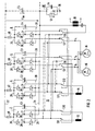
- FIG. 1 shows a basic circuit diagram of a first embodiment of a drive converter according to the invention.
- This Drive converter has four sub-converters 2, 4, 6 and 8, a switching matrix 10 and a plurality of load elements 12, 14, 16 and 18.
- the four sub-converters 2 to 8 point each have the same phase modules 20, each of which can be switched off Use thyristors as power semiconductors.
- phase modules 20 have been used in traction drives for years used and are in the EPE article mentioned in the introduction described in detail.
- the outputs 21 of the phase modules 20 of the sub-converters 2 and 4 are by means of the switch matrix 10 each with a low-voltage traction winding 12 and 14 of a traction transformer, not shown connectable. Switches S9, S10, S11 and S12 are provided. These sub-converters 2 and 4 form thus one infeed converter, which is also used as Four-quadrant (4q-S) is called.
- the voltage intermediate circuit has a positive and a negative Busbar 22 and 24 and one of several capacitors C1, ..., C4 existing capacitor bank.
- the capacitors C1, ..., C4 are on the sub-converters 2, 4, 6 and 8 divided.
- the sub-converters 6 and 8 form a load-side converter and an auxiliary power inverter. Instead of the Auxiliary inverter functions include also the function Resistance brake possible.
- the capacitors C1, ..., C4 are each electrically parallel to the DC connections 26 and 28 of the sub-converters 2 to 8 switched.
- the Outputs 21 of these sub-converters 6 and 8 are each with a connection of a switch S5, S6, S7 and S8 of the switch matrix 10 connected. Each switch is on the output side S5, S6, S7 with a connection of the drive motor 16 and the switch S8 with a transformer for auxiliary companies connected.
- the other connection of each switch S5, S6, S7 and S8 is with an output 21 of the sub-converters 2 and 4 electrically connected.
- the circuit shown the switch S5 to S12 of this switch matrix 10 is on Excerpt from the possible links of the switch S5 to S12 of this switch matrix 10. With this switch matrix 10, it should be possible for each sub-converter 2 to 8 is connectable to each load element 12 to 18 and that everyone Sub-converters 2 to 8 replace each sub-converter 2 to 8 can. Only by linking using the switch matrix 10, the sub-converters 2 to 8 receive a function such as infeed converters, inverters or auxiliary operating converters.
- the DC connections 28 of the sub-converters 2 to 8 are directly connected to the negative busbar 24 of the voltage intermediate circuit of the drive converter, whereas the DC connections 26 of the sub-converters 2 to 8 each with a switch S1, S2, S3 and S4 with the positive Busbar 22 of the voltage intermediate circuit of the drive converter are connected.
- Shown in this The embodiment is the negative busbar 24 by means of a high impedance 30, consisting of a parallel connection a resistor 32 and a capacitor 34, with the ground 36 of the drive converter linked.
- the switches S1, ..., S4 can also the DC connections 28 of the sub-converter 2, 4, 6 and 8 with the negative busbar 24 of the voltage intermediate circuit, whereas the DC connections 26 of the converters 2, 4, 6 and 8 with the positive busbar 22 are connected. In this case is the high impedance 30 with the positive busbar 22 connected.
- a control device is provided for actuating the switches S1,... S4 and the changeover switches S5 to S12 of the changeover matrix 10, to which actual values i R, S, T, U ZK and U1 of the drive converter are supplied.
- This control device is not shown in detail for reasons of clarity. These actual values are the motor currents i R, S, T and the DC link DC voltage U ZK , which are recorded anyway by the drive control for control purposes.
- the actual value U1 is detected at the high impedance 30 and indicates whether there is an earth fault (U1 ⁇ 0).
- this control device determines which switch S1, ..., S4 and which changeover switch S5, ..., S12 must be actuated.
- control device Depending on these determined actuation signals, the control device also generates switchover signals, which switch the control signals for the sub-converters 6 and 8 in the drive control, which implement the function of a load-side converter, and the sub-converters 2 and 4 in accordance with the new converter circuit.
- Switches S1, ..., S4 are closed in normal operation and the switches S5 to S12 of the switch matrix 10 are shown in FIG the position shown.
- the voltage U1 at the high Impedance 30 is zero.
- the following table 1 shows which switches S1, ..., S4 have to be opened in which failure of the sub-converters 2, 4, 6 and 8.
- the tractive force and the power of the drive inverter are given in percent for each fault.
- Converter failure Open switch Press the switch traction power Sub-converter 2 S1 S9, S10 100% 50%
- the effort to implement the drive system shown is extremely low and lies mainly in the switch S1, ... S4, one of the busbars 22, 24 of the voltage intermediate circuit with a DC voltage connection 26 or 28 make the sub-converters 3, 4, 6 and 8 connectable.
- This Switches S1, ..., S4 must handle the high surge discharge currents in the event of a fault from the intermediate circuit capacitors C1, ..., C4 withstand.
- the switches S5 to S12 are stressed and the permissible inductances completely uncritical. You can work together on shift drums spatially arranged in a switching matrix 10 become.
- the low-inductance design of the intermediate circuit which is basically used for converters Desired with switchable power semiconductor switches is disturbed less. That is, the number of switches is kept as small as possible so that an inexpensive low inductor Structure of the DC link is still possible.
- This first embodiment of the drive converter enables a specially optimized for the requirements of rail traffic fault-tolerant drive system, despite which Severe failure occurs the full traction preserved. This can result in scheduled traffic be maintained.
- FIG. 2 shows a basic circuit diagram of a second embodiment of the drive converter according to the invention.
- the switches S1, ..., S4 by fuse 40 has been replaced.
- fuse 40 instead of the switches S1, ... S4 can volume and cost be significantly reduced again.
- Behavior in the event of errors Error class a) remains as described.
- the desired fuse 40 is triggered as a result of the surge current from the discharge of the intermediate circuit capacitors C1, ... C4 off.
- These fuses 40 are robustly oversized, since they are not scarce as in other applications must be designed above the nominal current. Rather, it applies the high melting integral when the intermediate circuit is discharged.
- Allowing fuse 40 to respond can be the desired fuse 40 by turning on (simultaneously) both controllable Semiconductors in the affected phase module 20 from the drive control to be triggered. Is this also (e.g. due to errors in the control electronics), this can Task from the second phase module 20 of the sub-converter concerned 2, 4, 6 or 8 can be adopted.
Landscapes
- Engineering & Computer Science (AREA)
- Power Engineering (AREA)
- Life Sciences & Earth Sciences (AREA)
- Sustainable Development (AREA)
- Sustainable Energy (AREA)
- Transportation (AREA)
- Mechanical Engineering (AREA)
- Business, Economics & Management (AREA)
- Emergency Management (AREA)
- Electric Propulsion And Braking For Vehicles (AREA)
- Control Of Electric Motors In General (AREA)
- Dc-Dc Converters (AREA)
- Supply And Distribution Of Alternating Current (AREA)
Claims (10)
- Convertisseur de puissance d'entraínement ayant un circuit intermédiaire de tension comportant une batterie de condensateurs constituée de plusieurs condensateurs (C1, ..., C4) et au moins sept modules de phase (20) de même type qui présentent chacun des semi-conducteurs de puissance déconnectables et sont en liaison électriquement conductrice avec les barres conductrices (22, 24) du circuit intermédiaire de tension, caractérisé en ce que deux modules de phase (20) et un condensateur (C1, ..., C4) branché en parallèle forment respectivement un sous-convertisseur de puissance (2, 4, 6, 8) qui peut être séparé d'une barre conductrice (22, 24) du circuit intermédiaire de tension, l'autre barre conductrice (24, 22) étant reliée au moyen d'une grande impédance (30) à la prise de terre (36) du convertisseur de puissance d'entraínement, et que chaque sortie (21) des modules de phase (20) peut être reliée au moyen d'une matrice de commutation (10) présentant plusieurs inverseurs (S5, ..., S12), à un élément de charge (12, 14, 16, 18), un dispositif de commande étant prévu pour actionner les inverseurs (S5, ..., S12) de cette matrice de commutation (10).
- Convertisseur de puissance d'entraínement selon la revendication 1, trois modules de phase (20) et un condensateur branché en parallèle formant respectivement un sous-convertisseur de puissance.
- Convertisseur de puissance d'entraínement selon la revendication 1, un commutateur (S1, ..., S4) étant prévu pour séparer les sous-convertisseurs de puissance.
- Convertisseur de puissance d'entraínement selon la revendication 1, un fusible de sécurité (40) étant prévu pour séparer les sous-convertisseurs de puissance.
- Convertisseur de puissance d'entraínement selon les revendications 1 et 4, un condensateur (C5) supplémentaire étant monté entre les barres conductrices (22, 24) du circuit intermédiaire de tension.
- Convertisseur de puissance d'entraínement selon la revendication 1, des dispositifs de détection de valeurs de mesure pour le courant et la tension étant associés à chaque sous-convertisseur de puissance.
- Convertisseur de puissance d'entraínement selon la revendication 1, des valeurs instantanées (iR, S, T, UZK) du convertisseur de puissance d'entraínement étant transmises au dispositif de commande.
- Convertisseur de puissance d'entraínement selon la revendication 1, des enroulements de traction côté basse tension, des moteurs d'entraínement et un transformateur auxiliaire étant prévus comme éléments de charge (12, 14, 16, 18).
- Convertisseur de puissance d'entraínement selon la revendication 1, une résistance ohmique étant prévue comme élément de charge.
- Convertisseur de puissance d'entraínement selon la revendication 1, un dispositif d'amortissement des surtensions étant prévu comme élément de charge.
Applications Claiming Priority (2)
| Application Number | Priority Date | Filing Date | Title |
|---|---|---|---|
| DE19610800 | 1996-03-19 | ||
| DE19610800A DE19610800C1 (de) | 1996-03-19 | 1996-03-19 | Fehlertoleranter Stromrichter |
Publications (3)
| Publication Number | Publication Date |
|---|---|
| EP0796757A2 EP0796757A2 (fr) | 1997-09-24 |
| EP0796757A3 EP0796757A3 (fr) | 1998-01-07 |
| EP0796757B1 true EP0796757B1 (fr) | 2001-11-14 |
Family
ID=7788767
Family Applications (1)
| Application Number | Title | Priority Date | Filing Date |
|---|---|---|---|
| EP97103748A Expired - Lifetime EP0796757B1 (fr) | 1996-03-19 | 1997-03-06 | Fault tolerant motor drive power converter |
Country Status (5)
| Country | Link |
|---|---|
| EP (1) | EP0796757B1 (fr) |
| JP (1) | JP3041293U (fr) |
| AT (1) | ATE208716T1 (fr) |
| DE (2) | DE19610800C1 (fr) |
| ES (1) | ES2168532T3 (fr) |
Families Citing this family (11)
| Publication number | Priority date | Publication date | Assignee | Title |
|---|---|---|---|---|
| DE102005059423A1 (de) * | 2005-12-13 | 2007-06-21 | Airbus Deutschland Gmbh | Verfahren und Einrichtung zur redundanten Versorgung von mehreren elektrischen Stell-oder Antriebsmotoren durch eine gemeinsame Leistungselektronikeinheit |
| JP5017163B2 (ja) * | 2008-04-01 | 2012-09-05 | 株式会社日立製作所 | 鉄道車両の駆動装置 |
| JP2012065489A (ja) * | 2010-09-17 | 2012-03-29 | Toyo Electric Mfg Co Ltd | 鉄道車両用制御装置 |
| CN102361344A (zh) * | 2011-10-10 | 2012-02-22 | 株洲南车时代电气股份有限公司 | 列车dc600v列供装置3组份实现装置及实现方法 |
| DK2634885T3 (en) | 2012-02-29 | 2015-11-23 | Abb Technology Ltd | DC power system with system protection features |
| DE102016218453A1 (de) | 2016-09-26 | 2018-03-29 | Siemens Aktiengesellschaft | Elektrisches Wandlersystem |
| CN107017816B (zh) * | 2017-04-25 | 2019-06-04 | 南京航空航天大学 | 具有容错能力的电动汽车驱动和充电系统及故障重构方法 |
| CN110877619B (zh) * | 2018-09-06 | 2021-01-26 | 株洲中车时代电气股份有限公司 | 一种列车救援供电电路、控制方法及装置 |
| DE102019200874A1 (de) | 2019-01-24 | 2020-07-30 | Audi Ag | Schaltanordnung für einen Elektromotor eines Fahrzeugs |
| CN109941108B (zh) * | 2019-04-02 | 2021-11-12 | 中车株洲电力机车有限公司 | 轨道交通车辆及其故障保护方法 |
| CN111204363B (zh) * | 2020-04-23 | 2020-07-24 | 湖南中车时代通信信号有限公司 | 一种牵引系统故障诊断预警和状态评估方法、装置及系统 |
Family Cites Families (5)
| Publication number | Priority date | Publication date | Assignee | Title |
|---|---|---|---|---|
| JP2862579B2 (ja) * | 1989-08-18 | 1999-03-03 | 株式会社東芝 | 車両用電源装置 |
| JP2878725B2 (ja) * | 1989-09-11 | 1999-04-05 | 株式会社東芝 | 電気車制御装置 |
| US5309073A (en) * | 1991-10-21 | 1994-05-03 | Hitachi, Ltd. | Electric vehicle control device |
| SE502191C2 (sv) * | 1993-09-30 | 1995-09-11 | Asea Brown Boveri | Förfarande och anordning för kompensering av bortfall av en växelriktare |
| US5491622A (en) * | 1994-01-07 | 1996-02-13 | Delco Electronics Corp. | Power converter with emergency operating mode for three phase induction motors |
-
1996
- 1996-03-19 DE DE19610800A patent/DE19610800C1/de not_active Expired - Fee Related
-
1997
- 1997-03-06 DE DE59705320T patent/DE59705320D1/de not_active Expired - Fee Related
- 1997-03-06 AT AT97103748T patent/ATE208716T1/de not_active IP Right Cessation
- 1997-03-06 ES ES97103748T patent/ES2168532T3/es not_active Expired - Lifetime
- 1997-03-06 EP EP97103748A patent/EP0796757B1/fr not_active Expired - Lifetime
- 1997-03-10 JP JP1997002072U patent/JP3041293U/ja not_active Expired - Lifetime
Also Published As
| Publication number | Publication date |
|---|---|
| ES2168532T3 (es) | 2002-06-16 |
| DE59705320D1 (de) | 2001-12-20 |
| JP3041293U (ja) | 1997-09-09 |
| DE19610800C1 (de) | 1997-07-24 |
| ATE208716T1 (de) | 2001-11-15 |
| EP0796757A3 (fr) | 1998-01-07 |
| EP0796757A2 (fr) | 1997-09-24 |
Similar Documents
| Publication | Publication Date | Title |
|---|---|---|
| DE102010060380B3 (de) | Notbetriebsfähige Pitchmotor-Antriebsschaltung | |
| EP0832006B1 (fr) | Systeme convertisseur haute tension | |
| EP1318589B1 (fr) | Système à énergie éolienne et procédé de fonctionnement d'un tel système | |
| EP2596980B1 (fr) | Convertisseur de courant à plusieurs points avec hacheur de freinage | |
| DE3431934C2 (fr) | ||
| DE10217889A1 (de) | Stromversorgung mit einem Direktumrichter | |
| EP2319168A2 (fr) | Convertisseur à résistances de freinage réparties | |
| EP0796757B1 (fr) | Fault tolerant motor drive power converter | |
| DE3106895A1 (de) | Fehlerstrom-erfassungs-isolier- und beseitigungsanordnung | |
| EP1782527B1 (fr) | Dispositif d'alimentation de groupes auxiliaires destines a un vehicule propulsé par combustible ou électricité | |
| DE3817652C2 (fr) | ||
| EP3882071A1 (fr) | Véhicule, en particulier véhicule ferroviaire | |
| DE19941481B4 (de) | Elektrisch gesteuertes, dezentrales Steuersystem in einem Fahrzeug | |
| EP1782526B1 (fr) | DISPOSITIF D'ALIMENTATION DE GROUPES AUXILIAIRES DESTINES A UN VEHICULE PROPULSÉ PAR COMBUSTIBLE OU ÉLECTRICITÉ& xA; | |
| EP3586418B1 (fr) | Réseau de tension électrique continue à haute redondance | |
| EP3622621A1 (fr) | Onduleur à plusieurs niveaux | |
| EP0514580B1 (fr) | Convertisseur | |
| EP0340686B1 (fr) | Appareil d'attaque pour un électromoteur | |
| EP3602714B1 (fr) | Réseau de tension continue redondant | |
| EP0730333A2 (fr) | Système de propulsion d'un bâteau | |
| EP0989016B1 (fr) | Circuit de conversion de puissance avec configuration variable pour applications à la traction | |
| WO2018138017A1 (fr) | Module à semi-conducteur | |
| DE19908495A1 (de) | Transformatorlose Einspeiseschaltung für Bahnfahrzeuge | |
| DE19648948C1 (de) | Wechselrichter mit Bremssteller | |
| DE3029851C2 (de) | Schaltungsanordnung zur signaltechnisch sicheren Ansteuerung eines Stromverbrauchers |
Legal Events
| Date | Code | Title | Description |
|---|---|---|---|
| PUAI | Public reference made under article 153(3) epc to a published international application that has entered the european phase |
Free format text: ORIGINAL CODE: 0009012 |
|
| AK | Designated contracting states |
Kind code of ref document: A2 Designated state(s): AT BE CH DE ES FR IT LI |
|
| PUAL | Search report despatched |
Free format text: ORIGINAL CODE: 0009013 |
|
| AK | Designated contracting states |
Kind code of ref document: A3 Designated state(s): AT BE CH DE ES FR IT LI |
|
| 17P | Request for examination filed |
Effective date: 19980205 |
|
| 17Q | First examination report despatched |
Effective date: 19991028 |
|
| GRAG | Despatch of communication of intention to grant |
Free format text: ORIGINAL CODE: EPIDOS AGRA |
|
| GRAG | Despatch of communication of intention to grant |
Free format text: ORIGINAL CODE: EPIDOS AGRA |
|
| GRAH | Despatch of communication of intention to grant a patent |
Free format text: ORIGINAL CODE: EPIDOS IGRA |
|
| RIC1 | Information provided on ipc code assigned before grant |
Free format text: 7B 60L 3/00 A |
|
| GRAH | Despatch of communication of intention to grant a patent |
Free format text: ORIGINAL CODE: EPIDOS IGRA |
|
| GRAA | (expected) grant |
Free format text: ORIGINAL CODE: 0009210 |
|
| AK | Designated contracting states |
Kind code of ref document: B1 Designated state(s): AT BE CH DE ES FR IT LI |
|
| REF | Corresponds to: |
Ref document number: 208716 Country of ref document: AT Date of ref document: 20011115 Kind code of ref document: T |
|
| REG | Reference to a national code |
Ref country code: CH Ref legal event code: EP |
|
| REG | Reference to a national code |
Ref country code: CH Ref legal event code: NV Representative=s name: SIEMENS SCHWEIZ AG |
|
| REF | Corresponds to: |
Ref document number: 59705320 Country of ref document: DE Date of ref document: 20011220 |
|
| PGFP | Annual fee paid to national office [announced via postgrant information from national office to epo] |
Ref country code: AT Payment date: 20020220 Year of fee payment: 6 |
|
| PGFP | Annual fee paid to national office [announced via postgrant information from national office to epo] |
Ref country code: ES Payment date: 20020321 Year of fee payment: 6 Ref country code: BE Payment date: 20020321 Year of fee payment: 6 |
|
| PGFP | Annual fee paid to national office [announced via postgrant information from national office to epo] |
Ref country code: FR Payment date: 20020326 Year of fee payment: 6 |
|
| PGFP | Annual fee paid to national office [announced via postgrant information from national office to epo] |
Ref country code: DE Payment date: 20020521 Year of fee payment: 6 |
|
| PGFP | Annual fee paid to national office [announced via postgrant information from national office to epo] |
Ref country code: CH Payment date: 20020610 Year of fee payment: 6 |
|
| REG | Reference to a national code |
Ref country code: ES Ref legal event code: FG2A Ref document number: 2168532 Country of ref document: ES Kind code of ref document: T3 |
|
| PLBE | No opposition filed within time limit |
Free format text: ORIGINAL CODE: 0009261 |
|
| STAA | Information on the status of an ep patent application or granted ep patent |
Free format text: STATUS: NO OPPOSITION FILED WITHIN TIME LIMIT |
|
| 26N | No opposition filed | ||
| PG25 | Lapsed in a contracting state [announced via postgrant information from national office to epo] |
Ref country code: AT Free format text: LAPSE BECAUSE OF NON-PAYMENT OF DUE FEES Effective date: 20030306 |
|
| PG25 | Lapsed in a contracting state [announced via postgrant information from national office to epo] |
Ref country code: ES Free format text: LAPSE BECAUSE OF NON-PAYMENT OF DUE FEES Effective date: 20030307 |
|
| PG25 | Lapsed in a contracting state [announced via postgrant information from national office to epo] |
Ref country code: LI Free format text: LAPSE BECAUSE OF NON-PAYMENT OF DUE FEES Effective date: 20030331 Ref country code: CH Free format text: LAPSE BECAUSE OF NON-PAYMENT OF DUE FEES Effective date: 20030331 Ref country code: BE Free format text: LAPSE BECAUSE OF NON-PAYMENT OF DUE FEES Effective date: 20030331 |
|
| BERE | Be: lapsed |
Owner name: *SIEMENS A.G. Effective date: 20030331 |
|
| PG25 | Lapsed in a contracting state [announced via postgrant information from national office to epo] |
Ref country code: DE Free format text: LAPSE BECAUSE OF NON-PAYMENT OF DUE FEES Effective date: 20031001 |
|
| REG | Reference to a national code |
Ref country code: CH Ref legal event code: PL |
|
| PG25 | Lapsed in a contracting state [announced via postgrant information from national office to epo] |
Ref country code: FR Free format text: LAPSE BECAUSE OF NON-PAYMENT OF DUE FEES Effective date: 20031127 |
|
| REG | Reference to a national code |
Ref country code: FR Ref legal event code: ST |
|
| REG | Reference to a national code |
Ref country code: ES Ref legal event code: FD2A Effective date: 20030307 |
|
| PG25 | Lapsed in a contracting state [announced via postgrant information from national office to epo] |
Ref country code: IT Free format text: LAPSE BECAUSE OF NON-PAYMENT OF DUE FEES Effective date: 20050306 |