EP0796566A2 - Apparatus for pitting prunes or dates - Google Patents
Apparatus for pitting prunes or dates Download PDFInfo
- Publication number
- EP0796566A2 EP0796566A2 EP97630016A EP97630016A EP0796566A2 EP 0796566 A2 EP0796566 A2 EP 0796566A2 EP 97630016 A EP97630016 A EP 97630016A EP 97630016 A EP97630016 A EP 97630016A EP 0796566 A2 EP0796566 A2 EP 0796566A2
- Authority
- EP
- European Patent Office
- Prior art keywords
- pitting
- rubber
- assembly
- cam
- along
- Prior art date
- Legal status (The legal status is an assumption and is not a legal conclusion. Google has not performed a legal analysis and makes no representation as to the accuracy of the status listed.)
- Withdrawn
Links
Images


Classifications
-
- A—HUMAN NECESSITIES
- A23—FOODS OR FOODSTUFFS; TREATMENT THEREOF, NOT COVERED BY OTHER CLASSES
- A23N—MACHINES OR APPARATUS FOR TREATING HARVESTED FRUIT, VEGETABLES OR FLOWER BULBS IN BULK, NOT OTHERWISE PROVIDED FOR; PEELING VEGETABLES OR FRUIT IN BULK; APPARATUS FOR PREPARING ANIMAL FEEDING- STUFFS
- A23N4/00—Machines for stoning fruit or removing seed-containing sections from fruit, characterised by their stoning or removing device
- A23N4/02—Machines for stoning fruit or removing seed-containing sections from fruit, characterised by their stoning or removing device for stoning fruit
- A23N4/08—Machines for stoning fruit or removing seed-containing sections from fruit, characterised by their stoning or removing device for stoning fruit for dates, olives or the like oblong fruits
Definitions
- the invention is an apparatus for pitting prunes, dates, or other soft articles (e.g., soft, dried fruit having a sticky outer surface). More particularly, the invention is an apparatus for seating an article (e.g., a prune) between chucks of a chain-driven chuck assembly, and moving a pitting knife into engagement with the article to eject a pit from within the article as the chuck assembly is translated around a processing path.
- an article e.g., a prune
- the invention is an apparatus for pitting articles such as prunes or dates.
- Each article is loaded between chuck jaws of a chain-driven chuck assembly at a feed station, and the chuck assembly then translates the article between stations along a process path.
- the chuck assembly translates the article to a pitting turret where a pitting rubber moves into position below the chuck assembly.
- the chuck assembly and pitting rubber then translate together (as a unit) around the pitting turret to a pitting station where a pitting knife engages the article and ejects a pit therefrom.
- the chuck assembly then translates the pitted article to a discharge station (typically located away from the pitting turret) where the pitted article is discharged from the chuck assembly.
- the apparatus includes a rotatable feed unit, a rotatable pitting turret, a chain around the feed unit and pitting turret, and a drive assembly for rotating the pitting turret about its axis.
- a number of chuck assemblies e.g., seventy or eighty
- each chuck assembly having a fixed chuck jaw fixedly attached to the chain and a sliding chuck jaw slidably mounted to the fixed jaw.
- the pitting turret includes a pitting rubber holder to which a relatively small number of pitting rubbers (e.g., eighteen pitting rubbers) are mounted, and a pitting knife for each pitting rubber.
- Each pitting rubber supports one prune while a pitting knife engages the prune to eject the prune's pit.
- the turret causes the chain to translate, thereby translating each chuck assembly along a closed path around the feed unit and the pitting turret.
- each pitting rubber and the knife corresponding thereto translate along a curved (e.g., circular) path around the turret's central axis.
- a portion of the path of each chuck assembly coincides with a portion of the curved path of one of the pitting rubbers, in the sense that a pitting rubber positioned below the chuck assembly moves together (as a unit) with the chuck assembly along the coinciding portion of their paths (sometimes referred to herein as the "common path" of the chuck assembly and pitting rubber).
- a knife which also translates along the common path (above the chuck assembly) moves down through the chuck assembly and rubber (to eject a pit from an article, as the article is held by the chuck assembly and rests on the rubber) and the knife then moves up away from the rubber and pitted article.
- the geometry of the preferred embodiment of the pitting turret permits use of a pit detection unit (during the pitting operation) for optically or mechanically monitoring the pitting operation to determine whether a pit is successfully ejected as a result of each engagement of a pitting knife with the article at the pitting station.
- the apparatus includes:
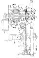
- Figure 1 is a perspective view of a preferred embodiment of the invention.
- Figure 2 is a side cross-sectional view of a portion of the Fig. 1 apparatus showing a pitting knife engaged with a prune, after the knife has pushed out a pit from within the prune.
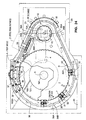
- Figure 3 is a simplified view (in a horizontal plane) of a portion of the Fig. 1 apparatus. The view is partially cross-sectional and partially elevational.
- Figure 4 is a side cross-sectional view (in a vertical plane) of the Fig. 1 apparatus.
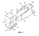
- Figure 5 is an exploded perspective view of one chuck assembly of the Fig. 1 apparatus, including a fixed chuck jaw and a sliding chuck jaw.
- Figure 6 is a top elevational view, and a side elevational view, of a portion of the chain of the Fig. 1 apparatus, with fixed chuck jaws attached thereto.
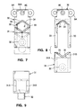
- Figure 7 is a top elevational view of a chuck assembly of the Fig. 1 apparatus, in a closed position in which arms 33 of fixed chuck jaw 30 extend into grooves in the sides of sliding chuck jaw 31.
- Figure 8 is a top elevational view of the Fig. 7 chuck assembly, in a disassembled configuration in which arms 33 of the fixed chuck jaw are disengaged from the sliding chuck jaw.
- Figure 9 is an end view of sliding chuck jaw portion 31 of the Fig. 7 chuck assembly.
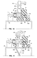
- Figure 10 is a simplified cross-sectional view of a portion of the Fig. 3 apparatus, in the plane determined by line 10'-10' of Fig. 3, showing the Fig. 7 assembly (on frame 20) in a fully closed position in which arms 33 of fixed jaw 30 extend as far as possible into grooves in the sides of sliding jaw 31, with extraneous product ejection wheel 42 above the chuck assembly.
- Figure 11 is a simplified cross-sectional view of a portion of the Fig. 3 apparatus, in the plane determined by line 11'-11' of Fig. 3, showing the Fig. 7 assembly (on frame 20 at a position over product discharge chute 106) in an open position in which arms 33 of fixed chuck jaw 30 extend only partially into grooves in the sides of sliding chuck jaw 31 so that a pitted prune can be ejected from between jaws 30 and 31 so as to fall into chute 106.
- Fig. 12 is a top elevational view of an adjustable portion of the feed disk assembly of the Fig. 1 apparatus.
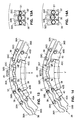
- Fig. 13 is a top elevational view of an adjustable portion of the feed disk assembly of the apparatus of Fig. 24, as it is rotated into a first position for receiving relatively small prunes.
- Fig. 13A is a top elevational view of three chuck assemblies as they translate between members 37 and 38, with members 37 and 38 in the first position (shown in Fig. 13).
- Fig. 14 is a top elevational view of the adjustable assembly of Fig. 13, as it is rotated into a second position for receiving relatively large prunes.
- Fig. 14A is a top elevational view of three chuck assemblies as they translate between members 37 and 38, with members 37 and 38 in the second position (shown in Fig. 14).
- Figure 15 is a side cross-sectional view of a portion of the pitting turret of the Fig. 1 apparatus.
- Figure 16 is a top elevational view of a portion of the pitting turret of Fig. 15, in plane 16' (identified in Fig. 15).
- Figure 16A is a side elevational view of eccentric bolt 143 (shown in Figs. 15 and 16).
- Figure 17 is a cross-sectional view of a portion of the pitting turret of Fig. 15, in the plane determined by line 17'-17' of Fig. 15.
- Figure 18 is an exploded perspective view of a portion of the assembly shown in Fig. 17.
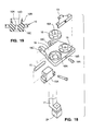
- Figure 19 is a side cross-sectional view of a pitting rubber of the assembly shown in Fig. 17.
- Figure 20 is a cross-sectional view of a portion of the pitting turret of Fig. 15, in the plane determined by line 20'-20' of Fig. 15.
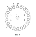
- Figure 21 is a cross-sectional view of mount 2A of the Fig. 4 apparatus, in the plane determined by line 21'-21' of Fig. 4.
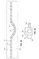
- Figure 22 is a view of generally cylindrical cam members 11A and 11B of Fig. 4, as they would appear if a cut (in a vertical plane in Fig. 1) were made through them, and they were then unrolled and flattened into the Fig. 22 plane.
- Figure 23 is a top elevational view of one cam follower 10 of the type shown in Figs. 4 and 22.
- Figure 24 is a partial, simplified cross-sectional view (in a horizontal plane) of an alternative embodiment of the inventive apparatus.
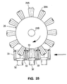
- Figure 25 is a cross-sectional view of knockout wheel 26 of Fig. 24, in the plane determined by line 25'-25' of Fig. 24.
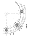
- Figure 26 is a top elevational view of a portion of the feed disk assembly of the Fig. 24 apparatus.
- This embodiment is an apparatus for pitting prunes, dates, or other soft articles (typically, remoisturized, dried fruits each having a sticky outer surface), in which chain-driven chuck assemblies translate the articles between stations along a process path.
- the articles to be pitted will be denoted as prunes, since it is contemplated that they will typically be remoisturized prunes or dates.
- this term is not intended to imply that the preferred embodiment is capable of pitting only prunes, or that the claimed invention is limited to an apparatus capable of pitting only prunes.
- the preferred embodiment includes rotatable feed disk 1, rotatable pitting turret 12, frame 20 (which supports disk 1 and turret 12), chain 9 which extends around feed disk 1 and turret 12.
- Turret 12 is free to rotate about its vertically oriented central shaft 2, and disk 1 is free to rotate about its vertically oriented hub 5.
- Motor 4 (coupled to shaft 2) is provided for rotating shaft 2, thereby rotating pitting turret 12 about the central longitudinal axis of shaft 2.
- a number of chuck assemblies are attached to chain 9, with each chuck assembly having a fixed portion (30 or 30') fixedly attached to chain 9 and a sliding portion (31) slidably mounted to the fixed portion.
- Pitting rubber holder 28 (including pitting rubber mounts 8, blocks 15A, and pins 15, better shown in Figs. 4, 17, and 18) rotates as a unit with (and is hingedly mounted to) shaft 2, and supports a relatively small number of pitting rubbers 16 (e.g., eighteen pitting rubbers).
- Pitting turret 12 also includes one pitting knife 6 for each pitting rubber 16. Each pitting rubber 16 supports one prune while one of the pitting knives 6 engages the prune to eject the prune's pit.
- Sprocket 13 of turret 12 has teeth 13A around its outer peripheral surface
- feed disk 1 has teeth 3 around its outer peripheral surface
- chain 9 extends around sprocket 13 and disk 1.
- teeth 13A cause chain 9 to translate, thereby translating each chuck assembly attached to chain 9 along a closed path around feed disk 1 and turret 12 (and causing disk 1 to rotate about hub 5).
- Each chuck assembly includes a roller 32.
- Cam member 21 is mounted around a portion of turret 12 (in the plane of rollers 32), as shown in Fig. 16.
- Cam members 36A, 36B, 37, 38, 37', and 38' are mounted around a portion of disk 1 (in the plane of rollers 32).
- Cam members 36A and 36B extend into the space between disk 1 and turret 12 (also in the plane of rollers 32).
- Cam member 36B also extends around turret 12 in the plane of rollers 32 (as shown in Fig. 16).
- the space between cam members 36A and 36B, between cam members 21 and 36B, between cam members 37' and 38', and between cam members 37 and 38, is a cam track (36) which guides rollers 32 of the chuck assemblies around the above-mentioned closed path.
- each pitting rubber 16 translates along a generally circular path (below the plane of chain 9) around turret 12's central axis, and a knife (6) corresponding to each pitting rubber translates along a generally circular path (above the plane of chain 9) around turret 12's central axis.
- Platform 121 is fixedly mounted on disk 1
- generally conical hub member 5A is fixedly mounted on platform 121.
- Elements 1, 121, and 5A are coaxial with hub 5, and thus when chain 9 rotates disk 1, elements 1, 121, 5A, and 5 rotate together as a unit about the central (vertical) axis of hub 5.
- feed chute 100 is fixedly (but adjustably) mounted to frame 20 above member 5A. Prunes 7 are loaded onto the apparatus (e.g., by being dropped from a feed conveyor positioned above chute 100 and member 5A).
- chute 100 When chute 100 is provided, prunes fall through chute 100 and out through the generally annular space between member 5A and the lower end of chute 100.
- the position of chute 100 can be adjusted to control the size of this generally annular space, and thus to control the rate at which prunes fall onto member 5A and platform 121.
- Member 5A functions to divert prunes that fall onto it radially outward (toward the outer periphery of disk 1) onto platform 121.
- prunes then fall from platform 121 onto disk 1, and a stream of the prunes then moves onto the chuck assemblies (preferably at a substantially uniform loading rate) as the chuck assemblies pass through prune infeed station A (shown in Fig. 1 and better shown in Fig. 3).
- chute 100 is omitted, and prunes are simply dropped onto member 5A so as to fall onto platform 121 and then onto disk 1.
- a water mist is sprayed onto station A to improve the handling characteristics of the prunes being loaded onto the chuck assemblies.
- a branch line can be connected to the water line which feeds nozzle 105, and the mist for station A can be emitted from a mist nozzle connected to the end of this branch line.
- Hub member 5A preferably has a truncated cone shape, with a conical top and flat side faces 5B as shown.
- Horizontal blade 108 (preferably made of metal) is fixedly attached to frame 20 so as to extend between member 5A and frame in a plane just above the plane of platform 121. Thus, blade 108 wipes the surface of platform 121 (as chain 9 rotates disk 1 and platform 121 together as a unit), in order to direct prunes on platform 121 radially outward so as to fall onto disk 1 at station A.
- Wiper blade 109 (fixedly mounted to frame 20 by rod 109A as shown, and preferably made of rubber) is positioned just above the surface of disk 1, so as to wipe the surface of disk 1 (as chain 9 rotates disk 1 and platform 121 together as a unit), in order to direct prunes on disk 1 at station A radially outward onto the chuck assemblies being translated by chain 9.
- prune distributing elements such as elements 130, 131, and 132 are positioned along track 36 to even out the distribution of prunes on the chuck assemblies (to promote seating of one and only one prune between the jaws of each chuck assembly, and to divert extraneous prunes back onto disk 1 for translation back to infeed station A).
- Element 130 is a passively rotatable wheel (whose center is mounted to frame 20 by a rod as shown). Wheel 130 rotates passively (in a horizontal plane) in response to being struck by prunes riding past it at the boundary between disk 1 and the chuck assemblies, thereby redistributing these prunes.
- Blade 131 (preferably made of plastic) is fixedly mounted to frame 20 (by a rod as shown) in a position above the path of the chuck assemblies, and tube assembly 132 (comprising vertically oriented lengths of rubber tubing attached to a frame, which frame is fixedly mounted to frame 20 by a rod as shown) is also positioned above the path of the chuck assemblies.
- Blade 131 and the rubber tubes of assembly 132 function to clear extraneous prunes (prunes which are not seated between the jaws of the chuck assemblies) away from the chuck assemblies that pass below them, and to promote the seating of a single prune between the jaws of each chuck assembly.
- Outer wall 120 extends around part of disk 1's outer periphery.
- cover 101 (shown in Fig. 4 and partially shown in Fig. 3) is mounted to wall 120 over station A and members 37, 38, 37', and 38'.
- the function of wall 120 (preferably made of hard plastic) and cover 101 (preferably made of metal) is to confine the prunes within the feed disk unit of the inventive apparatus.
- Wall 120 overhangs the upper surface of sliding jaw 31 of each chuck assembly (at least part of the way around disk 1). Thus, wall 120 will push (toward hub 5) any prunes that ride on jaws 31, thereby preventing the prunes from falling off the feed disk unit.
- cover 101 preferably covers those chuck assemblies whose jaws periodically open and close as pins 32 of the chuck assemblies translate between members 37 and 38 (and members 37' and 38') thus preventing prunes from escaping from the feed disk unit.
- rotating paddle wheel 42 (driven by motor 41 shown in Fig. 1) sweeps any non-seated prunes (prunes that are not properly seated between chuck jaws of the chuck assemblies) away from the chuck assemblies, before the chuck assemblies proceed toward the pitting turret.
- each chuck assembly that translates away from station B toward pitting turret 12 is either empty (i.e., carries no prune), or carries one properly seated prune between its chucks.
- Wheel 42 is rotatably mounted to motor 41 by shaft 42A (as best shown in Figs. 3 and 10). Motor 41 drives wheel 42 by rotating shaft 42A.
- wall 120 extends around station B, and optionally a cover (not shown) that is similar to (but smaller than) cover 101 is mounted over station B, to prevent prunes from escaping from the feed disk unit at station B.
- each chuck assembly will sometimes be denoted herein as a "prune carrier” or simply as a “carrier.”
- each carrier (and the prune, if any, carried thereby) translates to pitting turret 12, where the carrier meets a pitting rubber 16 in the sense that the rubber 16 moves into a position below the carrier.
- the carrier and the rubber 16 then translate together as a unit along a generally circular path (around shaft 2) to pit discharge station C.
- one of the pitting knives 6 engages the prune (if any) in the carrier, forces the prune down against rubber 16, and ejects the prune's pit (by pushing the pit out from within the prune and then through a hole in rubber 16).
- the carrier After the pitting operation at station C, the carrier translates the pitted prune to pitted prune discharge station D.
- an air or water jet of the type to be described below (or a knockout wheel 26 of the type shown in Figs. 24 and 25) pushes the pitted prune downward out from between the jaws of the carrier into a product discharge chute (chute 106 of Fig. 11) below frame 20.
- motor 4 causes shaft 2 to rotate at a rate such that 1000 to 1200 carriers per minute pass through pit discharge station C.
- the chuck assemblies of the inventive apparatus are attached along (and driven along a process path) by a belt or looped member other than a chain consisting of links.
- a belt or looped member other than a chain consisting of links.
- chain is used herein in a broad sense denoting all looped members, including belts (e.g., belts made of a continuous loop of material) as well as chains (e.g., the preferred chain described herein which comprises links 9A and 9B shown in Fig. 6).
- each prune (or date or other article) being processed is carried from infeed station A to discharge station D between the chuck jaws of a single chuck apparatus; a movably mounted pitting rubber 16 meets the chuck apparatus at (or just before) pit discharge station C, so that the pitting rubber is available to support the prune when the pitting knife engages the prune; and all pitting rubbers 16 are mounted so as to be easily accessible (i.e., for removal and replacement) when each has been moved away from the chuck apparatus.
- the apparatus can include a substantially smaller number of pitting rubbers (e.g., eighteen pitting rubbers) each of which is mounted for quick and convenient removal and replacement (e.g., due to damage or wear).
- pitting rubbers e.g., eighteen pitting rubbers
- FIG. 5 is an exploded perspective view of one of the preferred chuck assemblies, including fixed chuck jaw 30 (sometimes denoted as a fixed "jaw") and sliding chuck jaw 31 (sometimes denoted as a sliding "jaw").
- chain 9 is made of links 9A and 9B, with one link 9B connecting each pair of links 9A.
- Each fixed jaw 30 is designed to be fixedly mounted to one link 9A of chain 9.
- Each of the slightly differently shaped fixed jaws 30' (shown in Fig. 6), is designed to be fixedly mounted to one link 9B of chain 9.
- One of sliding jaws 31 is slidably mounted to each of jaws 30 and 30' (in a manner to be explained below).
- Jaw 30 has a central portion with V-shaped faces 34, two parallel arms 33 which extend out from the sides of the central portion, and a hole 30A through the central portion to be aligned with a corresponding hole 9C (shown in Fig. 6) through link 9A, so that a rivet 9E can be inserted through aligned holes 30A and 9C for mounting the central portion to link 9A.
- Jaw 30' is identical to jaw 30, except in that its central portion has a narrower end opposite faces 34 (as shown in Fig. 6), and in that a hole 30B extends through its central portion for alignment with a corresponding hole 9D through link 9B (so that a rivet 9E can be inserted through aligned holes 30B and 9D for mounting the central portion to link 9B).
- each jaw 30' has a narrower end than does jaw 30 so that the end of jaw 30' can fit between two adjacent links 9A (as shown in Fig. 6) when jaw 30' is mounted to link 9B and a jaw 30 is mounted to each link 9A.
- Sliding jaw 31 has grooves 31A and 31B in its side walls for receiving arms 33 of jaw 30 (or 30'). Sliding jaw 31 also has a central portion with V-shaped faces 35, and a roller 32 which extends downward from the bottom face of the central portion. Roller 32 preferably includes a pin fixedly attached to jaw 31's central portion and a roller portion around the pin, with the roller portion having freedom to rotate relative to the pin.
- the inner portion of sliding jaw 31 (the portion which faces fixed jaw 30 or 30') preferably extends above the upper edges of faces 34 and 35, thus defining a face 31E of jaw 31 (shown in Fig. 5 and also in Figs.
- Jaw 31 also has a recessed surface 31F (preferably formed by counterboring the bottom portion of face 35). Surface 31F is dimensioned to receive part of a neck portion of a pitting rubber (neck portion 16B of pitting rubber 16 to be described below), to avoid deformation of the pitting rubber during the pitting operation.
- Each of fixed jaws 30 and 30' similarly has a recessed surface 30F (shown in Fig. 2 but not visible in Fig. 5), preferably formed by counterboring the bottom portion of face 34 of jaw 30 or 30'. Recessed surface 30F functions to receive part of the pitting rubber neck whose opposite portion fits against surface 31F of the sliding jaw 31 opposite the fixed jaw (in an assembled chuck assembly).
- each sliding jaw 31 is composed of hard plastic (such as Delrin material) except that each roller 32 is preferably made of metal.
- each fixed jaw 30 (and 30') is composed of metal (such as brass).
- a chuck assembly To assemble a chuck assembly, the end of a fixed jaw's central portion is attached to link of chain 9 by a rivet (e.g., jaw 30 is attached to link 9A by rivet 9E, as shown in Figs. 6, 7, and 8). Then, grooves 31A and 31B of a sliding jaw 31 are aligned with arms 33 of the fixed jaw (as shown in Fig. 8). Then, grooves 31A and 31B are slid onto arms 33 (as shown in Fig. 7) and roller 32 of sliding jaw 31 is inserted in the cam track between cam members 36A and 36B (or 37 and 38).
- jaw 31 When the chuck assembly is so assembled (as shown in Figs. 10 and 11), jaw 31 is free to slide along arms 33 relative to jaw 30 (or 30') in the directions of the double-headed arrow of Fig. 11.
- the chuck assembly is designed to receive a prune in the space surrounded by faces 34 and 35 and arms 33 (i.e., space Z shown in Fig. 7), as prune 7 (shown in Fig. 2) is held in a chuck assembly.
- the inner portion of sliding jaw 31 (which faces fixed jaw 30) preferably extends above the upper edges of faces 34 and 35, thus defining a face 31E of jaw 31 (best shown in Figs. 10 and 11) whose function is to guide a prune into (and retain the prune in) the "central space" surrounded by faces 34 and 35 and arms 33.
- the faces 31E of the jaws 31 around feed disk 1 define a "live wall.” At least a portion of the live wall oscillates radially (relative to hub 5 of disk 1 in a manner to be explained below) to promote the guiding of prunes into the central space of each chuck assembly.
- Fig. 2 also shows a pitting rubber 16 positioned below the chuck assembly shown in Fig. 2.
- Pitting rubber 16 has a hole 16A therethrough for receiving the blade portion of knife 6, and a neck portion 16B surrounding the upper end of hole 16A.
- the tubular end portion of each knife 6 is denoted herein as a "blade portion" although typically the distal end of such end portion (having annular cross-section) is not sharpened.
- Fig. 2 shows the blade portion of one of pitting knives 6 engaged with prune 7 (at an instant just after the blade portion has pushed prune 7 down against rubber 16, and then pushed pit 8 out from within prune 7 and out through the lower end of hole 16A.
- neck 16B of rubber 16 is sandwiched between prune 7 and jaws 30 and 31 to keep meat from the prune from squeezing through between pitting rubber 16 and the chuck assembly.
- Jaw 31 has a recessed surface 31F (formed by counterboring the bottom portion of face 35 of jaw 31) which receives a portion of neck 16B
- jaw 30 has a recessed surface 30F (formed by counterboring the bottom portion of face 34 of jaw 30) which receives the opposite portion of neck 16B.
- each knife 6 translates between a pair of parallel knife clearing blades 160 (shown in Figs. 2 and 16). As each knife rises vertically after pitting a prune, blades 160 function by clearing from each knife 6 any pit or prune material that clings to the knife.
- roller 32 of each chuck assembly rides in the cam track (36) between cam members 36A and 36B, between cam members 21 and 36B, between cam members 37 and 38, and between cam members 37' and 38', as chain 9 translates the chuck assembly around the above-mentioned closed path.
- Cam track 36 extends perpendicularly to the plane of both Fig. 10 and Fig. 11, so that the chuck assembly shown in Fig. 10 (and Fig. 11) is free to translate perpendicularly into the plane of Fig. 10 (and Fig. 11) as chain 9 translates along sprocket 3 around the outer edge of disk 1.
- Cam members 36A and 36B shown in Figs. 10 and 11
- cam member 21 shown in Fig. 16
- cam members 37, 38, 37', and 38' shown in Fig. 12
- Fig. 10 shows the chuck assembly (in the plane determined by line 10'-10' of Fig. 3) at a point at which the chuck assembly is closed (in the sense that faces 34 of jaw 30 abut faces 35 of jaw 31, and arms 33 of fixed jaw 30 extend as far as possible through jaw 31).
- member 36B extends under faces 34 and 35, thus preventing any prune (or prune fragment) from falling through the chuck assembly to the area below frame 20.
- Rotating paddle wheel 42 (driven by motor 41 shown in Fig. 1 but not in Fig. 10) sweeps any prune that is not properly seated between jaws 30 and 31 away from the chuck assembly, before the chuck assembly proceeds toward the pitting turret.
- Wheel 42 consists of a central portion fixedly attached to shaft 42A.
- the central portion has a number of arms which extend out radially therefrom, and a short rubber tube 42C is fitted onto the end of each arm 42B.
- Flexible tubes 42C engage the non-seated prunes, and move them away without damaging them.
- roller 32 follows the radially varying cam track portion defined by the space between members 36A and 36B (and then between members 21 and 36B) around the pitting turret to the pitting station.
- the cam track portion defined by the space between members 36A and 36B and between members 21 and 36B is "radially varying" in the sense that its radial distance, from the center of shaft 2, varies with angular position around the periphery of the pitting turret.
- Fig. 11 shows the chuck assembly at pitted prune discharge station D (in the plane determined by line 11'-11' of Fig. 3), at a point at which track 36 causes roller 32 of the chuck assembly to be separated from chain 9, so that the chuck assembly is open (in the sense that faces 34 of jaw 30 are separated from faces 35 of jaw 31, and arms 33 of fixed jaw 30 do not extend as far as possible into jaw 31).
- the hole through member 36B provides access for a pitted prune (not shown in Fig. 11) carried by the chuck assembly to be ejected, by a jet of water (or pressurized air) escaping from nozzle 104 (or by knockout wheel 26 shown in Figs.
- roller 32 follows the radially varying cam track portion defined by the space between members 37 and 38 (and then between members 37' and 38') around feed disk 1.
- the cam track portion defined by the space between members 37 and 38 (and between members 37' and 38') is "radially varying" in the sense that its radial distance, from the center of hub 5, varies with angular position around the periphery of disk 1.
- FIG. 12 A portion of cam track 36 around feed disk 1 of the preferred embodiment is shown in Fig. 12.
- FIG. 13 and 14 A corresponding portion of cam track 36 around feed disk 1 of the alternative embodiment of Fig. 24 is shown in Figs. 13 and 14).
- the difference between the embodiment of Fig. 12 and that of Figs. 13 and 14 is that the former embodiment has two independently controllable adjustable cam track pairs (37,38 and 37'38') and the latter embodiment has one adjustable cam track pair (37,38). It is usually better to employ a relatively long adjustable portion of cam track 36 (which can be achieved by using both pairs 37,38 and 37',38' having a relatively long combined length) than a relatively short adjustable portion of cam track 36 (e.g., by using only pair 37,38 as in the embodiment of Figs.
- the portion of cam track 36 between member 37 and 38 (and between members 37' and 38') has a radius (relative to the center of hub 5) which varies sinusoidally.
- the purpose of this sinusoidal variation is to urge one prune to seat itself in a vertical orientation (with the longest axis of the prune oriented vertically) between the fixed and sliding jaw of each chuck assembly.
- the chuck assembly periodically opens (into a configuration as shown in Fig. 11) and closes (into a configuration as shown in Fig. 10).
- cam track 36 (along which a sliding jaw of each chuck assembly rides) has an adjustable cam track portion at prune infeed station A, which is defined by the assembly including members 37 and 38.
- This assembly can be adjusted (by manipulating adjustment screw 45) to vary the initial maximum spacing between the fixed and sliding jaw of each chuck assembly at the prune infeed station.
- cam member 37 (adjustably mounted to cam member 36A by pivoting members 39) and cam member 38 (adjustably mounted to cam member 36B by pivoting members 40) perform this function.
- members 39 are pivoted about pivots 39A, 39B, 39C, and 39D in the directions shown in Fig. 13, to move member 37 toward hub 5 (in the direction of arrow X of Fig. 13), and members 40 are pivoted about pivots 40A, 40B, 40C, and 40D in the directions shown in Fig. 13, to move member 38 toward hub 5 (in the direction of arrow X of Fig. 13).
- members 39 are pivoted about pivots 39A, 39B, 39C, and 39D in the directions shown in Fig. 14, to move member 37 away from hub 5 (in the direction of arrow Y of Fig. 14), and members 40 are pivoted about pivots 40A, 40B, 40C, and 40D in the directions shown in Fig. 14, to move member 38 away from hub 5 (in the direction of arrow Y of Fig. 14).
- This allows a larger prune to fall between the jaws of each chuck assembly.
- Fig. 13A is a top elevational view of three chuck assemblies, whose rollers 32 have the positions 32A, 32B, and 32C (shown in Fig. 13), respectively, as they translate between members 37 and 38, with members 37 and 38 in the first position (shown in Fig. 13).
- the maximum gap between faces 34 and faces 35 is shown in Fig. 13A to be "S1", and the average gap between faces 34 and 35 of the three assemblies is relatively small.
- Fig. 14A is a top elevational view of three chuck assemblies, whose rollers 32 have the positions 32D, 32E, and 32F, (shown in Fig. 14) respectively, as they translate between members 37 and 38, with members 37 and 38 in the second position (shown in Fig. 14).
- the maximum gap between faces 34 and faces 35 of these three assemblies is shown in Fig. 14A to be "S2" (which is substantially greater than S1 shown in Fig. 13A), and the average gap between faces 34 and 35 of the three assemblies is larger in Fig. 14A than in Fig. 13A.
- S2 which is substantially greater than S1 shown in Fig. 13A
- the average gap between faces 34 and 35 of the three assemblies is larger in Fig. 14A than in Fig. 13A.
- larger prunes can be seated between the jaws of the assemblies of Fig. 14A than between the jaws of the assemblies of Fig. 13A.
- the radius (relative to the center of hub 5) of the portion of cam track 36 which surrounds disk 1 varies periodically (in a manner other than sinusoidally).
- the preferred embodiment of Fig. 12 includes all elements of the Fig. 13 embodiment, and also includes a second set of similar elements (including members 37', 38' and adjustment screw 45').
- the second set of elements is adjustable independently from the first set (by manipulating adjustment screw 45') to vary the maximum spacing between the fixed and sliding jaw of each chuck assembly as the assembly translates along track 36 after passing between members 37 and 38. As shown in Fig.
- cam member 37' is adjustably mounted to cam member 36A by pivoting member 39 and to pivoting member 139' by pivoting member 39'
- member 39' is rotatably attached to member 139' by pivot 39B'
- member 139' is rotatably attached to cam member 37 by pivot 39C'
- cam member 37 is adjustably mounted to cam member 36A by another pivoting member 39.
- cam member 38' is adjustably mounted to cam member 36B by pivoting member 40 and to pivoting member 140' by pivoting member 40'
- member 40' is rotatably attached to member 140' by pivot 40B'
- member 140' is rotatably attached to cam member 38 by pivot 40C'
- cam member 38 is adjustably mounted to cam member 36B by another pivoting member 40.
- screw 45 is advanced to push members 37 and 38 radially inward (thereby pivoting member 39 about pivots 39C and 39D, pivoting member 40 about pivots 40C and 40D, pivoting member 139' about pivots 39B' and 39C', and pivoting member 140' about pivots 40B' and 40C').
- screw 45' is typically also advanced to push members 37' and 38' radially inward by a similar amount (thereby pivoting member 39' about pivots 39A' and 39B', pivoting member 39 on the left side of Fig. 12 about pivots 39A and 39B, pivoting member 40' about pivots 40A' and 40B', and pivoting member 40 about pivots 40A and 40B).
- screw 45 is retracted (toward the top of Fig. 12) to pull members 37 and 38 radially outward (thereby pivoting member 39 in the opposite direction about pivots 39C and 39D, pivoting member 40 in the opposite direction about pivots 40C and 40D, pivoting member 139' in the opposite direction about pivots 39B' and 39C', and pivoting member 140' in the opposite direction about pivots 40B' and 40C').
- This allows a larger prune to fall between the jaws of each chuck assembly.
- screw 45' is typically also retracted (toward the top of Fig. 12) to pull members 37' and 38' radially outward by a similar amount (thereby pivoting member 39' in the opposite direction about pivots 39A' and 39B', pivoting member 39 on the left side of Fig. 12 in the opposite direction about pivots 39A and 39B, pivoting member 40' in the opposite direction about pivots 40A' and 40B', and pivoting member 40 in the opposite direction about pivots 40A and 40B).
- the remaining portion of track 36 around disk 1 is not sinusoidally varying, and instead has a relatively small radius causing each chuck assembly to translate along it in a closed position (as shown in Fig. 10) in which each chuck assembly grips any prune seated between its faces 34 and 35. Only when the chuck assembly reaches the pitting turret does track 36 cause its jaws to open (but at this point, they open only for a short time and then close again before the chuck assembly reaches pit discharge station C).
- Pitting turret 12 includes mount member 2A (which is fixedly attached to shaft 2 (as shown in Figs. 4 and 21), and eighteen identical pitting knives 6, each pitting knife mounted in a cylindrical, vertically oriented, channel 2B (shown in Fig. 21) through mount member 2A. As shown in Fig. 21, member 2A has eighteen channels 2B, each for receiving one of knives 6. Member 2A rotates as a unit with shaft 2 relative to frame 20 (including tower portion 20A of frame 20).
- a cam follower 10 (having an inner end 10A) rigidly attached to each knife 6 is slidably mounted to member 2A, with each inner end 10A extending into a vertically oriented channel 50 defined by member 2A.
- An outer end of each cam follower 10 rides in the gap (which is a cam track 11) between upper cam member 11A and lower cam member 11B.
- Cam members 11A and 11B which are fixedly attached to tower portion 20A of frame 20, remain fixed while the assembly comprising shaft 2, member 2A, knives 6, cam followers 10, support member 14 (to be discussed below), and pitting rubber holder 28 and cam follower arms 17 (to be discussed below) rotates relative to frame 20.
- each cam follower 10 rides in the gap (cam track 11) between upper cam member 11A and lower cam member 11B.
- Each of members 11A and 11B has a cylindrical outer surface.
- Track 11 has a dip 11X (shown in Figs. 1 and 22) at the location of pit discharge station C, and raised portion 11Y at locations away from station C.
- the shape of track 11 is best shown in Fig. 22, which is a view of members 11A and 11B, as they would appear if a cut (in a vertical plane) were made through them, and they were then unrolled and flattened into the Fig. 22 plane.
- cam follower 10 A preferred embodiment of cam follower 10 is shown in Fig. 23.
- member 10 has a central portion 10B adapted to be placed around one of knives 6 (each knife 6 has a generally cylindrical cross-section), and then tightened in place by advancing a bolt through threaded channel 10D extending through portion 10B.
- End portion 10A is fixedly attached to one face of portion 10B, so that end portion 10A can slide up and down along the channel 50 associated with the knife 6.
- Block-shaped end portion 10C is fixedly attached to the opposite face of portion 10B, so that end portion 10C can slide along cam track 11 between upper cam member 11A and lower cam member 11B as described above.
- Pitting turret 12 also includes support member 14 (fixedly attached to shaft 2, as shown in Fig. 15), and pitting rubber holder 28 which is pivotally attached to member 15A by pivot pins 15 (member 15A is in turn fixedly attached to member 14).
- holder 28 includes eighteen identical pitting rubbers 16 and nine identical pitting rubber mounts 18.
- Each pitting rubber 16 is preferably made of elastic material such as rubber, has a shape (e.g., the preferred shape shown in Fig. 2 and Fig.
- each rubber 16 is removably mounted to the apparatus simply by pressing it into a recessed portion 18A of mount member 18 (shown in Fig. 18). This is done by inserting cylindrical ridge 16C of rubber 16 into the recessed portion. Ridge 16C has sufficient length (in the vertical direction in Fig. 19) so that cup 16D of rubber 16 extends sufficiently far out of recessed portion 18A for knife 6 to press prune 7 forcefully against cup 16D and push the prune's pit all the way through hole 16A.
- pitting rubber is used herein, including in the claims, to denote an element for supporting an article being pitted, it is not essential that such element be composed of natural or synthetic rubber. On the contrary, alternative embodiments of the invention employ pitting rubbers composed of other material such as resilient plastic.
- Two rubbers 16 are mounted on each mount 18 by pressing each rubber 16 into a recessed portion 18A of mount 18 (shown in Fig. 18).
- a hold down plate 19 is then placed over a portion of both rubbers 16 (as best shown in Fig. 17), and plate 19 is then fastened to mount 18 by screwing screw 19A (shown in Fig. 18) into threaded hole 18B of mount 18.
- screw 19A shown in Fig. 18
- any one of pitting rubbers 16 becomes worn or damaged, it can readily be removed and replaced simply (after removing the corresponding screw 19A and lifting the corresponding plate 19, if plate 19 and screw 19A are used).
- This replacement operation can be conveniently performed without manipulating in any way the chuck assemblies or any component of pitting turret 12 (other than the relevant mount 18), except by rotating holder 28 about its central vertical axis as necessary to move the rubber 16 to be replaced to a convenient position.
- One or both of the pitting rubbers 16 that are held by a hold down plate 19 can be replaced when the plate 19 has been removed.
- Each mount 18 has two pin mounts 18C (shown in Fig. 18), and is pivotally mounted to block 15A by aligning mounts 18C with member 15A and then inserting pin 15 through aligned holes in member 15A and mounts 18C.
- Block 15A is fixedly attached to member 14 such as by screws.
- cam follower arm 17 is fixedly connected to each mount 18, as best shown in Fig. 15.
- a slide block 24 is mounted at the other end of each arm 17.
- a cam plate 22 is fixedly attached to assembly 29.
- Assembly 29 is fixedly attached to frame 20.
- the lower end of shaft 2 is rotatably mounted to bearing portion 2D of assembly 29.
- slide blocks 24 There are nine slide blocks 24 (one for each mount 18). Slide blocks 24 function as cam followers as they slide along the outer surface of cam plate 22 during rotation of shaft 2.
- the preferred shape for cam plate 22 is best shown in Fig. 20.
- the corresponding mount 18 pivots about pin 15 so that arm 17 is oriented substantially vertically (as is the right arm 17 in Fig. 15). This pivots the pitting rubbers 16 attached to the mount 18 up until they meet one of the chuck assemblies.
- This orientation occurs when the chuck assembly and the pitting rubber are at pit discharge station C.
- the purpose of pivoting rubber 16 up into engagement with a chuck assembly at station C is to put rubber 16 in position in which it supports a prune being held between the fixed and sliding jaw of the chuck assembly while one of knives 6 engages the prune, and to prevent any portion of the prune from being squeezed through the space between pitting rubber 16 and the chuck assembly during the pitting operation.
- cam member 150 is also mounted in the plane of plate 22, at a such a position that each slide block 24 encounters member 150 after a pit has been ejected through the hole 16A through each of the pitting rubbers 16 associated with the slide block.
- the curved inner surface 150A of member 150 has a varying radial distance away from center of shaft 2, and this radial distance decreases with increasing angle around shaft 2 for the following reason.
- member 150 positively pushes block 24 radially inward, thereby forcing the corresponding mount 18 to pivot about pin 15 so that arm 17 is oriented non-vertically (e.g., forcing each arm 17 into the position of the left arm 17 in Fig. 15), in turn pivoting the pitting rubbers 16 attached to the mount 18 downward to separate them from the chuck assemblies above them after the pitting rubbers 16 have passed through pitting station C. This prepares the chuck assemblies to undergo the pitted prune discharge operation at station D.
- Cam plate 22 and cam member 150 are preferably made of metal (e.g., brass).
- cam plate 22 The outer surface (cam track) of cam plate 22 is shaped and oriented relative to the cam track defined by the space between cam members 21 and 36B (shown in Fig. 16) to solve timing problems in the following sense. Due to the shape and orientation of both cam tracks, the configuration of a pitting rubber 16 and a corresponding chuck assembly is always synchronized with the position of a corresponding one of pitting knives 6.
- blocks 15A are mounted in alignment with channels 2B through member 2A so that each rubber 16 is aligned with one of knives 6, and the chuck assemblies are sized and mounted (and teeth 13A of sprocket 13 are aligned relative to blocks 15A) so that at pit discharge station C, one and only one chuck assembly is positioned between a pitting rubber 16 (below the chuck assembly) and a corresponding knife 6 (above the pitting rubber and chuck assembly).
- Each triplet of a knife 6, chuck assembly, and pitting rubber 16 rotates together as a unit through station C.
- the alignment of teeth 13A of sprocket 13 relative to shaft 2 can be adjusted using eccentric bolt 143 and bolts 144 which extend through plate 140 and sprocket 13).
- a portion of the path of each chuck assembly around pitting turret 12 coincides with a portion of the circular path of one of pitting rubbers 16, in that the pitting rubber moves together as a unit with the chuck assembly along a coinciding portion of their paths (a "common path" of the chuck assembly and pitting rubber).
- the knife 6 above the pitting rubber moves down (as it follows dip 11X in track 11) toward the rubber (to eject a pit from a prune being held by the chuck assembly which rests on the rubber) and the knife then moves up away from the rubber and pitted article.
- pitting knife 6 is brought into engagement with prune 7 to push pit 8 out from within prune 7 and through opening 16A in the center of pitting rubber 16.
- the ejected pit 8 is discharged into pit chute 110 (shown in Figs. 15 and 16) disposed below station C.
- Chute 110 has a central surface 110B (shown in Fig. 16) which preferably has the curvature of a portion of the surface of a cone directs the falling pits downward into a bin, a vertically oriented, trailing end surface 110A (shown in Figs. 15 and 16), and a vertically oriented, leading end surface 110C (shown in Fig. 16).
- wiping blade 112 preferably made of hard plastic
- a nozzle 111 is mounted to the apparatus so as to direct a jet of water toward blade 112 (and the adjacent portions of chute 110) during pitting operations, to help clear pits from blade 112 and the adjacent portions of chute 110.
- one or more vertically oriented blades 113 are mounted to surface 110A in positions for knocking away pits from pitting knives 6 as the knives rotate past chute 110 and blades 113, so that the pits are freed to fall down into chute 110.
- An advantage of the preferred embodiment is that the pitting turret pits all the prunes at a single, visually and mechanically accessible location, thus permitting convenient use of a pit detection unit (during each pitting operation) for monitoring (optically or mechanically) the pitting operation to determine whether a pit is successfully ejected as a result of each engagement of a pitting knife with the article at the pitting station.
- a pit detection unit (during each pitting operation) for monitoring (optically or mechanically) the pitting operation to determine whether a pit is successfully ejected as a result of each engagement of a pitting knife with the article at the pitting station.
- an optical sensor 112A can be mounted below the pitting station (e.g., through blade 112 as shown in Fig. 15) in a position for monitoring any pit that falls from the pitting rubber 16 of the pitting station.
- the relative alignment (about the central axis of shaft 2) of the cam tracks at the pitting turret and sprocket teeth 13A solves timing problems in ensuring that each triplet of knife 6, chuck assembly, and pitting rubber 16 has the proper relative alignment at all times (e.g., to compensate for manufacturing tolerances in the component parts of pitting turret 12).
- plate 140 is preferably mounted above sprocket 13 (as shown in Fig. 15) to permit adjustment of the angular orientation of sprocket 13 relative to member 14 (and thus relative to shaft 2).
- Plate 140 has seven holes (each having a circular periphery) therethrough.
- the first six of these holes are for receiving straight bolts 144, and the seventh is for receiving eccentric bolt 143.
- Sprocket 13 has one hole 142 (having a radially oriented elongated periphery) therethrough and six holes 141 (each having an elongated, circumferentially oriented periphery) therethrough.
- hole 142 generally aligned with the seventh hole of plate 140 (with eccentric bolt 143 through these generally aligned holes (as shown in Fig. 16)
- each of holes 141 is generally aligned with one of the other six holes through plate 140 (so that a bolt 144 can be inserted through each of the latter six pairs of aligned holes).
- Eccentric bolt 143 (shown in Figs. 15 and 16, but better shown in Fig. 16A) is provided to adjust the orientation of sprocket 13 relative to shaft 2 as follows.
- Bolt 143 has hexagonal end portion 143A and pin 143B at its opposite end, and the central longitudinal axes of portion 143A and pin 143B are parallel but offset.
- member 14 has been fixedly mounted to shaft 2
- sprocket 13 has been placed on member 14
- plate 140 has been placed on sprocket 13 as shown in Fig. 15, the angular orientation of sprocket 13 relative to plate 140 (and thus relative to member 14 and shaft 2) can be changed by rotating bolt 143 which extends through the "seventh" hole of plate 140 into hole 142 of sprocket 13.
- pin 143B of bolt 143 moves radially along hcle 142 and the angular orientation of plate 140 rotates relative to sprocket 13.
- this orientation is preserved by screwing bolts 144 into the six other generally aligned hole pairs through plate 140 and sprocket 13.
- cam member 21 is mounted around a portion of turret 12 (in the plane of rollers 32) and cam member 36B is mounted around turret 12 (in the plane of rollers 32) as shown in Fig. 16.
- the space between cam member 21 and 36B is a cam track (a portion of above-discussed cam track 36) which guides roller 32 of the sliding jaw of each chuck assembly around turret 12.
- Fig. 16 also shows a chuck assembly in position X (just before pit discharge station C along the closed path of the chuck assembly), at a point at which the radius between the center of track 36 and the center of shaft 2 is at a maximum (the inner peripheral edge of member 21 at position X is separated by a large radial distance from the center of shaft 2).
- roller 32 of the chuck assembly in position X is maximally separated from shaft 2 and the chuck assembly is open (in the sense that faces 34 of jaw 30 are maximally separated from faces 35 of jaw 31, and arms 33 of fixed jaw 30 do not extend fully through jaw 31.
- This open configuration relaxes the chuck assembly's grip on the prune carried thereby, allowing the pitting knife to push the prune downward to seat the prune on the pitting rubber below the chuck assembly.
- Position X in Fig. 16 corresponds to position X in Fig. 20 at which cam 22 forces the corresponding arm 17 (arm 17 connected to mount 18 which supports the pitting rubber 16 below the chuck assembly) into a vertical orientation and pivots the corresponding pitting rubber 16 upward against the chuck assembly.
- positions Y in Fig. 16 corresponds to position Y1 or Y2 in Fig. 20 at which cam 22 forces the corresponding arm 17 into a vertical orientation and pivots the corresponding pitting rubber 16 upward against the chuck assembly (as cam 22 also does at position X in Fig. 20).
- cam member 21 is shaped so that it first opens each chuck assembly translating along it (at position X), and then closes the chuck assembly.
- the portion of member 36B opposite member 21 is correspondingly shaped, so that track 36 defined by the gap between members 36B and 21 has substantially constant width.
- cam member 150 causes the pitting rubber 16 associated therewith to separate from the chuck assembly. After this operation, chain 9 continues to translate each chuck assembly to station D, where the pitted prune discharge operation is performed.
- each chuck assembly continues to translate past a second jet of water (or pressurized air) escaping from second nozzle 105.
- This jet of fluid is directed downward into chute 107.
- wall 120 fixedly attached to frame 20
- prune material e.g., fragments of a prune
- a portion of wall 120 as the chuck assembly translates past said portion of wall 120.
- the fluid jet from nozzle 105 washes the dislodged prune material away from the chuck assembly, so that the material falls into waste chute 107.
- Figs. 24-26 We next describe an alternative embodiment of the invention with reference to Figs. 24-26. Those elements of the alternative embodiment that are identical to elements of the above-described preferred embodiment are identically numbered, and the description thereof will not be repeated below with reference to Figs. 24-26.
- the alternative embodiment of Figs. 24-26 differs in several respects from that of the above-described preferred embodiment: only one pair of adjustable cam members (37 and 38) is provided around a portion of disk 1 (as described above with reference to Figs. 13 and 14); cam member 5A' of Fig. 24 is conical (and does not have flat faces 5B as does corresponding member 5A of Fig.
- prune distributing elements 108, 130, 131, and 132 are omitted (although some or all of them can be included in variations on the embodiment of Figs. 24-26); chute 100 is omitted; and the entire portion of cam track 36 around disk 1 from station A through station B has a radius (relative to the center of hub 5) which varies sinusoidally.
- the preferred embodiment has a circular cam track 36 extending from pivots 39A and 40A through station B as shown in Fig. 3.
- cam track 36 of the alternative embodiment is determined by cam members 36A, 36B, 37, and 38 mounted around a portion of disk 1 (in the plane of rollers 32 of the chuck assemblies), cam members 36A and 36B extending between disk 1 and turret 12 (also in the plane of rollers 32), and cam members 36B and 21 extending around turret 12 in the plane of rollers 32.
- cam track 36 between stations A and B has a radius (relative to the center of hub 5) which varies sinusoidally.
- the purpose of this sinusoidal variation is to urge one prune to seat itself in a vertical orientation (with the longest axis of the prune oriented vertically) between the fixed and sliding jaw of each chuck assembly, as in the above-described preferred embodiment.
- the alternative embodiment employs knockout wheel 26 (best shown in Fig. 25) to perform this function.
- Wheel 26 is rotatably mounted to frame 20, at pitted prune discharge station D of the Fig. 24 apparatus, by horizontal shaft 26B (shown in Fig. 24 as well as in Fig. 25).
- Flexible rubber projections 26A are attached around the outer edge of wheel 26.
- each of projections 26A is hollow and substantially cylindrical in shape (projections 26A can be equal-length segments of a rubber tube, or the like).
- one of the projections 26A engages the pitted prune in the chuck assembly and ejects the pitted prune by pushing it down (away from the chuck assembly) into a chute (e.g., chute 106 shown in Fig. 11).
- cam track 36 which extends through station D directs the roller 32 of each chuck assembly away from the corresponding fixed jaw (30 or 30'), so that the each chuck assembly is open (with the fixed jaw separated from the sliding jaw) so that the jaws do not exert force on the pitted prune in opposition to the ejecting force exerted on the pitted prune by wheel 26.
- the force exerted (to the left in Fig. 25) on projections 26A by arms 33 of the chuck assemblies causes wheel 26 to rotate clockwise (as viewed in Fig. 25), thus bringing different projections 26A into successive engagement with different chuck assemblies.
- cam track 36 around disk 1 from station A through station B in the embodiment of Figs. 24-26 has a radius (relative to the center of hub 5) which varies sinusoidally.
- a section of this cam track 26 portion is shown in Fig. 26.
- the purpose of this sinusoidal variation is to urge one prune to seat itself in a vertical orientation (with the longest axis of the prune oriented vertically) between the fixed and sliding jaw of each chuck assembly.
- the jaws of each chuck assembly can grip a prune at points along track 36 where pin 32 is radially near to hub 5, and the jaws of each chuck assembly do not grip a prune at points along track 36 where pin 32 is radially far from hub 5.
- the faces 31E of sliding jaws 31 (around the portion of track 36 whose radius varies sinusoidally) define a "live wall.”
- the live wall oscillates radially (relative to hub 5 of disk 1) to promote the guiding of prunes into the space between the jaws of each chuck assembly.
- any of a wide variety of articles may be processed by the inventive apparatus.
- the invention has been described in embodiments suitable for processing prunes or dates.
- Such embodiments of the inventive apparatus includes apparatus (e.g., a portion of track 36 around disk 1 whose radius varies sinusoidally) for urging each prune into a vertical orientation in each chuck assembly (i.e., with the longest axis of the prune oriented vertically in the chuck assembly).
- apparatus e.g., a portion of track 36 around disk 1 whose radius varies sinusoidally
- the orientation of each article being pitted may be unimportant, and accordingly, the embodiments need not include apparatus for urging the articles into a preferred orientation.
- a chain (to which chuck assemblies are attached) is looped around a feed unit and a pitting turret, a motor actively drives the feed unit to rotate it about its hub (thus translating the chain), and the pitting turret is passively driven by the chain.
Abstract
An apparatus for pitting articles such as prunes or dates (7). Each article (7) is loaded between jaws of a chuck assembly which translates between stations along a process path. At a pitting turret (12), a pitting rubber (16) moves below the chuck assembly, and the chuck assembly and rubber translate together until a pitting knife (6) engages the article (7) and ejects a pit (8) therefrom. The chuck assembly then translates the pitted article (7) to a station where the pitted article (7) is discharged. Preferably, a relatively large number of chuck assemblies are provided, each having a fixed jaw (30) fixedly attached to a chain (9) and a sliding jaw (31) slidably mounted to the fixed portion. A relatively small number of pitting rubbers (16) and one pitting knife (6) for each rubber (16) are mounted to the pitting turret (12). Preferably, the apparatus includes a cam track (36) (for guiding each sliding jaw) having a portion whose radius varies sinusoidally with position around a feed unit, a portion around the pitting turret (12) for opening and then closing each chuck assembly, and an adjustable portion which can be adjusted to vary the initial maximum spacing between the fixed and sliding jaw (30, 31) of each chuck assembly. Preferably, the apparatus includes a second cam track for controlling vertical position of each pitting knife (6) and a third cam track for pivoting each pitting rubber (16) between a lowered orientation allowing access to the rubbers (16) for replacement and a raised orientation (at a pitting station) in which the rubber (16) supports a prune (7) while a knife (6) engages the prune (7). Preferably, the sliding jaws (31) have faces defining a live wall that oscillates (relative to the hub of a rotating feed unit) to promote the guiding of prunes (7) between the fixed and sliding jaw (30, 31) of each chuck assembly.

Description
- The invention is an apparatus for pitting prunes, dates, or other soft articles (e.g., soft, dried fruit having a sticky outer surface). More particularly, the invention is an apparatus for seating an article (e.g., a prune) between chucks of a chain-driven chuck assembly, and moving a pitting knife into engagement with the article to eject a pit from within the article as the chuck assembly is translated around a processing path.
- One type of conventional prune pitting machine is described in U.S. Patent 3,556,281, issued January 19, 1971. Another conventional prune pitting machine is described in U.S. Patent 3,153,473, issued October 20, 1964. However, such machines have had several limitations and disadvantages, including the following: they have had a large number of components, including a large number of components subject to wear and frequent replacement (e.g., more than three hundred pitting rubbers); they have required complicated and time-consuming maintenance, timing, and repair procedures (e.g., complicated disassembly in order to replace pitting rubbers); and they have required power-consuming means (e.g., fly wheel assembly 166 for vibrating the feed area of the apparatus of U.S. 3,153,473) for properly orienting a prune in each prune carrier.
- It had not been known until the present invention how to design an apparatus for pitting articles, such as prunes or dates, in a manner overcoming the noted disadvantages and limitations of conventional pitting apparatus.
- The invention is an apparatus for pitting articles such as prunes or dates. Each article is loaded between chuck jaws of a chain-driven chuck assembly at a feed station, and the chuck assembly then translates the article between stations along a process path. The chuck assembly translates the article to a pitting turret where a pitting rubber moves into position below the chuck assembly. The chuck assembly and pitting rubber then translate together (as a unit) around the pitting turret to a pitting station where a pitting knife engages the article and ejects a pit therefrom. The chuck assembly then translates the pitted article to a discharge station (typically located away from the pitting turret) where the pitted article is discharged from the chuck assembly.
- Preferably, the apparatus includes a rotatable feed unit, a rotatable pitting turret, a chain around the feed unit and pitting turret, and a drive assembly for rotating the pitting turret about its axis. A number of chuck assemblies (e.g., seventy or eighty) are attached to the chain, with each chuck assembly having a fixed chuck jaw fixedly attached to the chain and a sliding chuck jaw slidably mounted to the fixed jaw. Preferably, the pitting turret includes a pitting rubber holder to which a relatively small number of pitting rubbers (e.g., eighteen pitting rubbers) are mounted, and a pitting knife for each pitting rubber. Each pitting rubber supports one prune while a pitting knife engages the prune to eject the prune's pit. As the drive assembly rotates the turret, the turret causes the chain to translate, thereby translating each chuck assembly along a closed path around the feed unit and the pitting turret. Also as the drive assembly rotates the turret, each pitting rubber and the knife corresponding thereto translate along a curved (e.g., circular) path around the turret's central axis. A portion of the path of each chuck assembly coincides with a portion of the curved path of one of the pitting rubbers, in the sense that a pitting rubber positioned below the chuck assembly moves together (as a unit) with the chuck assembly along the coinciding portion of their paths (sometimes referred to herein as the "common path" of the chuck assembly and pitting rubber). As each chuck assembly and pitting rubber translate along the common path, a knife which also translates along the common path (above the chuck assembly) moves down through the chuck assembly and rubber (to eject a pit from an article, as the article is held by the chuck assembly and rests on the rubber) and the knife then moves up away from the rubber and pitted article.
- The geometry of the preferred embodiment of the pitting turret permits use of a pit detection unit (during the pitting operation) for optically or mechanically monitoring the pitting operation to determine whether a pit is successfully ejected as a result of each engagement of a pitting knife with the article at the pitting station.
- In preferred embodiments, the apparatus includes:
- a cam track (along which the sliding jaw of each chuck assembly rides), which has a first cam track portion around the feed unit whose radius (radial distance from the hub of the feed unit) varies sinusoidally (or periodically in a manner other than sinusoidally) to induce feeding of product between the jaws of each chuck assembly, a second cam track portion around the pitting turret for opening and then closing each chuck assembly as the chuck assembly translates along the common path, and an adjustable cam track portion at the feed station which is adjustable (relative to the center of the feed unit) to vary the initial maximum spacing between the fixed and sliding jaw of each chuck assembly at the feed station;
- an assembly for clearing non-seated articles from the chuck assemblies before they reach the pitting turret;
- a second cam track around the pitting turret for controlling the vertical position of each pitting knife;
- a third cam track around the pitting turret for pivoting each pitting rubber between a lowered orientation (away from the pitting station) and a raised orientation (at the pitting station); and
- an ejection means for ejecting each pitted article from its chuck assembly following the pitting operation (preferably the ejection means is an air or water jet, but alternatively it is a knockout wheel).
- Figure 1 is a perspective view of a preferred embodiment of the invention.
- Figure 2 is a side cross-sectional view of a portion of the Fig. 1 apparatus showing a pitting knife engaged with a prune, after the knife has pushed out a pit from within the prune.
- Figure 3 is a simplified view (in a horizontal plane) of a portion of the Fig. 1 apparatus. The view is partially cross-sectional and partially elevational.
- Figure 4 is a side cross-sectional view (in a vertical plane) of the Fig. 1 apparatus.
- Figure 5 is an exploded perspective view of one chuck assembly of the Fig. 1 apparatus, including a fixed chuck jaw and a sliding chuck jaw.
- Figure 6 is a top elevational view, and a side elevational view, of a portion of the chain of the Fig. 1 apparatus, with fixed chuck jaws attached thereto.
- Figure 7 is a top elevational view of a chuck assembly of the Fig. 1 apparatus, in a closed position in which
arms 33 of fixedchuck jaw 30 extend into grooves in the sides of slidingchuck jaw 31. - Figure 8 is a top elevational view of the Fig. 7 chuck assembly, in a disassembled configuration in which
arms 33 of the fixed chuck jaw are disengaged from the sliding chuck jaw. - Figure 9 is an end view of sliding
chuck jaw portion 31 of the Fig. 7 chuck assembly. - Figure 10 is a simplified cross-sectional view of a portion of the Fig. 3 apparatus, in the plane determined by line 10'-10' of Fig. 3, showing the Fig. 7 assembly (on frame 20) in a fully closed position in which
arms 33 offixed jaw 30 extend as far as possible into grooves in the sides of slidingjaw 31, with extraneousproduct ejection wheel 42 above the chuck assembly. - Figure 11 is a simplified cross-sectional view of a portion of the Fig. 3 apparatus, in the plane determined by line 11'-11' of Fig. 3, showing the Fig. 7 assembly (on
frame 20 at a position over product discharge chute 106) in an open position in whicharms 33 offixed chuck jaw 30 extend only partially into grooves in the sides of slidingchuck jaw 31 so that a pitted prune can be ejected from betweenjaws chute 106. - Fig. 12 is a top elevational view of an adjustable portion of the feed disk assembly of the Fig. 1 apparatus.
- Fig. 13 is a top elevational view of an adjustable portion of the feed disk assembly of the apparatus of Fig. 24, as it is rotated into a first position for receiving relatively small prunes.
- Fig. 13A is a top elevational view of three chuck assemblies as they translate between
members members - Fig. 14 is a top elevational view of the adjustable assembly of Fig. 13, as it is rotated into a second position for receiving relatively large prunes.
- Fig. 14A is a top elevational view of three chuck assemblies as they translate between
members members - Figure 15 is a side cross-sectional view of a portion of the pitting turret of the Fig. 1 apparatus.
- Figure 16 is a top elevational view of a portion of the pitting turret of Fig. 15, in plane 16' (identified in Fig. 15).
- Figure 16A is a side elevational view of eccentric bolt 143 (shown in Figs. 15 and 16).
- Figure 17 is a cross-sectional view of a portion of the pitting turret of Fig. 15, in the plane determined by line 17'-17' of Fig. 15.
- Figure 18 is an exploded perspective view of a portion of the assembly shown in Fig. 17.
- Figure 19 is a side cross-sectional view of a pitting rubber of the assembly shown in Fig. 17.
- Figure 20 is a cross-sectional view of a portion of the pitting turret of Fig. 15, in the plane determined by line 20'-20' of Fig. 15.
- Figure 21 is a cross-sectional view of
mount 2A of the Fig. 4 apparatus, in the plane determined by line 21'-21' of Fig. 4. - Figure 22 is a view of generally
cylindrical cam members - Figure 23 is a top elevational view of one
cam follower 10 of the type shown in Figs. 4 and 22. - Figure 24 is a partial, simplified cross-sectional view (in a horizontal plane) of an alternative embodiment of the inventive apparatus.
- Figure 25 is a cross-sectional view of
knockout wheel 26 of Fig. 24, in the plane determined by line 25'-25' of Fig. 24. - Figure 26 is a top elevational view of a portion of the feed disk assembly of the Fig. 24 apparatus.
- The processing stations of a preferred embodiment of the inventive apparatus will be described with reference to Figures 1 and 3. This embodiment is an apparatus for pitting prunes, dates, or other soft articles (typically, remoisturized, dried fruits each having a sticky outer surface), in which chain-driven chuck assemblies translate the articles between stations along a process path. During the description of the preferred embodiment, the articles to be pitted will be denoted as prunes, since it is contemplated that they will typically be remoisturized prunes or dates. However, use of this term is not intended to imply that the preferred embodiment is capable of pitting only prunes, or that the claimed invention is limited to an apparatus capable of pitting only prunes.
- The preferred embodiment includes
rotatable feed disk 1,rotatable pitting turret 12, frame 20 (which supportsdisk 1 and turret 12),chain 9 which extends aroundfeed disk 1 andturret 12.Turret 12 is free to rotate about its vertically orientedcentral shaft 2, anddisk 1 is free to rotate about its vertically orientedhub 5. Motor 4 (coupled to shaft 2) is provided forrotating shaft 2, thereby rotating pittingturret 12 about the central longitudinal axis ofshaft 2. - A number of chuck assemblies (e.g., seventy or eighty) are attached to
chain 9, with each chuck assembly having a fixed portion (30 or 30') fixedly attached tochain 9 and a sliding portion (31) slidably mounted to the fixed portion. Pitting rubber holder 28 (including pitting rubber mounts 8, blocks 15A, and pins 15, better shown in Figs. 4, 17, and 18) rotates as a unit with (and is hingedly mounted to)shaft 2, and supports a relatively small number of pitting rubbers 16 (e.g., eighteen pitting rubbers). Pittingturret 12 also includes one pittingknife 6 for each pittingrubber 16. Each pittingrubber 16 supports one prune while one of the pittingknives 6 engages the prune to eject the prune's pit. -
Sprocket 13 ofturret 12 hasteeth 13A around its outer peripheral surface,feed disk 1 hasteeth 3 around its outer peripheral surface, andchain 9 extends aroundsprocket 13 anddisk 1. Asmotor 4 andshaft 2 drive turret 12 (including sprocket 13) so thatturret 12 rotates (counter-clockwise, as shown in Fig. 3),teeth 13A cause chain 9 to translate, thereby translating each chuck assembly attached tochain 9 along a closed path aroundfeed disk 1 and turret 12 (and causingdisk 1 to rotate about hub 5). Each chuck assembly includes aroller 32. -
Cam member 21 is mounted around a portion of turret 12 (in the plane of rollers 32), as shown in Fig. 16.Cam members Cam members disk 1 and turret 12 (also in the plane of rollers 32).Cam member 36B also extends aroundturret 12 in the plane of rollers 32 (as shown in Fig. 16). The space betweencam members cam members cam members rollers 32 of the chuck assemblies around the above-mentioned closed path. - As
motor 4 rotatesshaft 2 andturret 12, each pittingrubber 16 translates along a generally circular path (below the plane of chain 9) aroundturret 12's central axis, and a knife (6) corresponding to each pitting rubber translates along a generally circular path (above the plane of chain 9) aroundturret 12's central axis. - We next describe the portion of the preferred embodiment which loads prunes between the jaws of each chuck assembly, with reference to Figs. 1, 3, and 4.
Platform 121 is fixedly mounted ondisk 1, and generallyconical hub member 5A is fixedly mounted onplatform 121.Elements hub 5, and thus whenchain 9 rotatesdisk 1,elements hub 5. - Optionally, feed
chute 100 is fixedly (but adjustably) mounted to frame 20 abovemember 5A.Prunes 7 are loaded onto the apparatus (e.g., by being dropped from a feed conveyor positioned abovechute 100 andmember 5A). Whenchute 100 is provided, prunes fall throughchute 100 and out through the generally annular space betweenmember 5A and the lower end ofchute 100. Preferably, the position ofchute 100 can be adjusted to control the size of this generally annular space, and thus to control the rate at which prunes fall ontomember 5A andplatform 121.Member 5A functions to divert prunes that fall onto it radially outward (toward the outer periphery of disk 1) ontoplatform 121. The prunes then fall fromplatform 121 ontodisk 1, and a stream of the prunes then moves onto the chuck assemblies (preferably at a substantially uniform loading rate) as the chuck assemblies pass through prune infeed station A (shown in Fig. 1 and better shown in Fig. 3). In alternative embodiments,chute 100 is omitted, and prunes are simply dropped ontomember 5A so as to fall ontoplatform 121 and then ontodisk 1. Preferably, a water mist is sprayed onto station A to improve the handling characteristics of the prunes being loaded onto the chuck assemblies. In embodiments in which a nozzle 105 (to be described below) is provided at station D for directing a water jet on chuck assemblies passing through station D, a branch line can be connected to the water line which feedsnozzle 105, and the mist for station A can be emitted from a mist nozzle connected to the end of this branch line. -
Hub member 5A preferably has a truncated cone shape, with a conical top and flat side faces 5B as shown. Horizontal blade 108 (preferably made of metal) is fixedly attached to frame 20 so as to extend betweenmember 5A and frame in a plane just above the plane ofplatform 121. Thus,blade 108 wipes the surface of platform 121 (aschain 9 rotatesdisk 1 andplatform 121 together as a unit), in order to direct prunes onplatform 121 radially outward so as to fall ontodisk 1 at station A. Wiper blade 109 (fixedly mounted to frame 20 byrod 109A as shown, and preferably made of rubber) is positioned just above the surface ofdisk 1, so as to wipe the surface of disk 1 (aschain 9 rotatesdisk 1 andplatform 121 together as a unit), in order to direct prunes ondisk 1 at station A radially outward onto the chuck assemblies being translated bychain 9. - Preferably, prune distributing elements such as
elements track 36 to even out the distribution of prunes on the chuck assemblies (to promote seating of one and only one prune between the jaws of each chuck assembly, and to divert extraneous prunes back ontodisk 1 for translation back to infeed station A).Element 130 is a passively rotatable wheel (whose center is mounted to frame 20 by a rod as shown).Wheel 130 rotates passively (in a horizontal plane) in response to being struck by prunes riding past it at the boundary betweendisk 1 and the chuck assemblies, thereby redistributing these prunes. Blade 131 (preferably made of plastic) is fixedly mounted to frame 20 (by a rod as shown) in a position above the path of the chuck assemblies, and tube assembly 132 (comprising vertically oriented lengths of rubber tubing attached to a frame, which frame is fixedly mounted to frame 20 by a rod as shown) is also positioned above the path of the chuck assemblies.Blade 131 and the rubber tubes ofassembly 132 function to clear extraneous prunes (prunes which are not seated between the jaws of the chuck assemblies) away from the chuck assemblies that pass below them, and to promote the seating of a single prune between the jaws of each chuck assembly. - As
chain 9 and the chuck assemblies translate around the central vertical axis of hub 5 (anddisk 1 rotates counter-clockwise about this axis as shown in Fig. 3), some of the prunes fall between (or on top of) the jaws of the chuck assemblies and are carried by the chuck assemblies to excess prune removal station B. - Outer wall 120 (fixedly attached to frame 20) extends around part of
disk 1's outer periphery. Optionally also, cover 101 (shown in Fig. 4 and partially shown in Fig. 3) is mounted to wall 120 over station A andmembers Wall 120 overhangs the upper surface of slidingjaw 31 of each chuck assembly (at least part of the way around disk 1). Thus,wall 120 will push (toward hub 5) any prunes that ride onjaws 31, thereby preventing the prunes from falling off the feed disk unit. If installed, cover 101 preferably covers those chuck assemblies whose jaws periodically open and close aspins 32 of the chuck assemblies translate betweenmembers 37 and 38 (and members 37' and 38') thus preventing prunes from escaping from the feed disk unit. - At excess prune removal station B, rotating paddle wheel 42 (driven by
motor 41 shown in Fig. 1) sweeps any non-seated prunes (prunes that are not properly seated between chuck jaws of the chuck assemblies) away from the chuck assemblies, before the chuck assemblies proceed toward the pitting turret. Thus, each chuck assembly that translates away from station B toward pittingturret 12 is either empty (i.e., carries no prune), or carries one properly seated prune between its chucks.Wheel 42 is rotatably mounted tomotor 41 byshaft 42A (as best shown in Figs. 3 and 10).Motor 41 drives wheel 42 by rotatingshaft 42A. Preferably,wall 120 extends around station B, and optionally a cover (not shown) that is similar to (but smaller than) cover 101 is mounted over station B, to prevent prunes from escaping from the feed disk unit at station B. - The preferred chuck assembly structure will be described below with reference to Figs. 2 and 5-11. For convenience, each chuck assembly will sometimes be denoted herein as a "prune carrier" or simply as a "carrier."
- From station B, each carrier (and the prune, if any, carried thereby) translates to pitting
turret 12, where the carrier meets a pittingrubber 16 in the sense that therubber 16 moves into a position below the carrier. The carrier and therubber 16 then translate together as a unit along a generally circular path (around shaft 2) to pit discharge station C. At station C, one of the pittingknives 6 engages the prune (if any) in the carrier, forces the prune down againstrubber 16, and ejects the prune's pit (by pushing the pit out from within the prune and then through a hole in rubber 16). - After the pitting operation at station C, the carrier translates the pitted prune to pitted prune discharge station D. At station D, an air or water jet of the type to be described below (or a
knockout wheel 26 of the type shown in Figs. 24 and 25) pushes the pitted prune downward out from between the jaws of the carrier into a product discharge chute (chute 106 of Fig. 11) belowframe 20. - In one preferred embodiment,
motor 4 causesshaft 2 to rotate at a rate such that 1000 to 1200 carriers per minute pass through pit discharge station C. - In alternative embodiments, the chuck assemblies of the inventive apparatus are attached along (and driven along a process path) by a belt or looped member other than a chain consisting of links. For convenience, the term "chain" is used herein in a broad sense denoting all looped members, including belts (e.g., belts made of a continuous loop of material) as well as chains (e.g., the preferred chain described herein which comprises
links - Next, various features of the preferred embodiment will be described in detail with reference to Figs. 1-23.
- Among the important aspects of the invention are the following: each prune (or date or other article) being processed is carried from infeed station A to discharge station D between the chuck jaws of a single chuck apparatus; a movably mounted pitting
rubber 16 meets the chuck apparatus at (or just before) pit discharge station C, so that the pitting rubber is available to support the prune when the pitting knife engages the prune; and all pittingrubbers 16 are mounted so as to be easily accessible (i.e., for removal and replacement) when each has been moved away from the chuck apparatus. Even in preferred implementations in which the apparatus includes a large number of chuck assemblies (e.g., seventy or eighty), it can include a substantially smaller number of pitting rubbers (e.g., eighteen pitting rubbers) each of which is mounted for quick and convenient removal and replacement (e.g., due to damage or wear). - The preferred chuck assembly structure will next be described with reference to Figs. 2 and 5-11. Figure 5 is an exploded perspective view of one of the preferred chuck assemblies, including fixed chuck jaw 30 (sometimes denoted as a fixed "jaw") and sliding chuck jaw 31 (sometimes denoted as a sliding "jaw"). As shown in Fig. 6,
chain 9 is made oflinks link 9B connecting each pair oflinks 9A. Each fixedjaw 30 is designed to be fixedly mounted to onelink 9A ofchain 9. Each of the slightly differently shaped fixed jaws 30' (shown in Fig. 6), is designed to be fixedly mounted to onelink 9B ofchain 9. One of slidingjaws 31 is slidably mounted to each ofjaws 30 and 30' (in a manner to be explained below). -
Jaw 30 has a central portion with V-shaped faces 34, twoparallel arms 33 which extend out from the sides of the central portion, and ahole 30A through the central portion to be aligned with acorresponding hole 9C (shown in Fig. 6) throughlink 9A, so that arivet 9E can be inserted through alignedholes jaw 30, except in that its central portion has a narrower end opposite faces 34 (as shown in Fig. 6), and in that ahole 30B extends through its central portion for alignment with acorresponding hole 9D throughlink 9B (so that arivet 9E can be inserted through alignedholes jaw 30 so that the end of jaw 30' can fit between twoadjacent links 9A (as shown in Fig. 6) when jaw 30' is mounted to link 9B and ajaw 30 is mounted to eachlink 9A. - Sliding
jaw 31 hasgrooves arms 33 of jaw 30 (or 30'). Slidingjaw 31 also has a central portion with V-shaped faces 35, and aroller 32 which extends downward from the bottom face of the central portion.Roller 32 preferably includes a pin fixedly attached tojaw 31's central portion and a roller portion around the pin, with the roller portion having freedom to rotate relative to the pin. The inner portion of sliding jaw 31 (the portion which faces fixedjaw 30 or 30') preferably extends above the upper edges offaces face 31E of jaw 31 (shown in Fig. 5 and also in Figs. 10 and 11) whose function is to guide a prune into (and retain the prune in) the "central space" surrounded byfaces arms 33 of each assembled chuck assembly.Jaw 31 also has a recessedsurface 31F (preferably formed by counterboring the bottom portion of face 35).Surface 31F is dimensioned to receive part of a neck portion of a pitting rubber (neck portion 16B of pittingrubber 16 to be described below), to avoid deformation of the pitting rubber during the pitting operation. Each of fixedjaws 30 and 30' similarly has a recessedsurface 30F (shown in Fig. 2 but not visible in Fig. 5), preferably formed by counterboring the bottom portion offace 34 ofjaw 30 or 30'. Recessedsurface 30F functions to receive part of the pitting rubber neck whose opposite portion fits againstsurface 31F of the slidingjaw 31 opposite the fixed jaw (in an assembled chuck assembly). - Preferably, each sliding
jaw 31 is composed of hard plastic (such as Delrin material) except that eachroller 32 is preferably made of metal. Also preferably, each fixed jaw 30 (and 30') is composed of metal (such as brass). - To assemble a chuck assembly, the end of a fixed jaw's central portion is attached to link of
chain 9 by a rivet (e.g.,jaw 30 is attached to link 9A byrivet 9E, as shown in Figs. 6, 7, and 8). Then,grooves jaw 31 are aligned witharms 33 of the fixed jaw (as shown in Fig. 8). Then,grooves roller 32 of slidingjaw 31 is inserted in the cam track betweencam members jaw 31 is free to slide alongarms 33 relative to jaw 30 (or 30') in the directions of the double-headed arrow of Fig. 11. - The chuck assembly is designed to receive a prune in the space surrounded by
faces faces face 31E of jaw 31 (best shown in Figs. 10 and 11) whose function is to guide a prune into (and retain the prune in) the "central space" surrounded byfaces arms 33. Considered together, thefaces 31E of thejaws 31 aroundfeed disk 1 define a "live wall." At least a portion of the live wall oscillates radially (relative tohub 5 ofdisk 1 in a manner to be explained below) to promote the guiding of prunes into the central space of each chuck assembly. - Fig. 2 also shows a pitting
rubber 16 positioned below the chuck assembly shown in Fig. 2. Pittingrubber 16 has ahole 16A therethrough for receiving the blade portion ofknife 6, and aneck portion 16B surrounding the upper end ofhole 16A. The tubular end portion of eachknife 6 is denoted herein as a "blade portion" although typically the distal end of such end portion (having annular cross-section) is not sharpened. Fig. 2 shows the blade portion of one of pittingknives 6 engaged with prune 7 (at an instant just after the blade portion has pushedprune 7 down againstrubber 16, and then pushedpit 8 out from withinprune 7 and out through the lower end ofhole 16A. - During pitting (when the blade portion of
knife 6 is engaged withprune 7 as shown in Fig. 2),neck 16B ofrubber 16 is sandwiched betweenprune 7 andjaws rubber 16 and the chuck assembly.Jaw 31 has a recessedsurface 31F (formed by counterboring the bottom portion offace 35 of jaw 31) which receives a portion ofneck 16B, andjaw 30 has a recessedsurface 30F (formed by counterboring the bottom portion offace 34 of jaw 30) which receives the opposite portion ofneck 16B. By including recessedsurfaces neck 16B whenneck 16B is sandwiched betweenprune 7 andjaws 30 and 31 (e.g., at times whenprune 7 is engaged by one of pitting knives 6). - At the pitting station, each
knife 6 translates between a pair of parallel knife clearing blades 160 (shown in Figs. 2 and 16). As each knife rises vertically after pitting a prune,blades 160 function by clearing from eachknife 6 any pit or prune material that clings to the knife. - As noted, the
roller 32 of each chuck assembly rides in the cam track (36) betweencam members cam members cam members chain 9 translates the chuck assembly around the above-mentioned closed path. -
Cam track 36 extends perpendicularly to the plane of both Fig. 10 and Fig. 11, so that the chuck assembly shown in Fig. 10 (and Fig. 11) is free to translate perpendicularly into the plane of Fig. 10 (and Fig. 11) aschain 9 translates alongsprocket 3 around the outer edge ofdisk 1.Cam members cam members - Fig. 10 shows the chuck assembly (in the plane determined by line 10'-10' of Fig. 3) at a point at which the chuck assembly is closed (in the sense that faces 34 of
jaw 30 abut faces 35 ofjaw 31, andarms 33 of fixedjaw 30 extend as far as possible through jaw 31). As shown in Fig. 10,member 36B extends under faces 34 and 35, thus preventing any prune (or prune fragment) from falling through the chuck assembly to the area belowframe 20. Rotating paddle wheel 42 (driven bymotor 41 shown in Fig. 1 but not in Fig. 10) sweeps any prune that is not properly seated betweenjaws Wheel 42 consists of a central portion fixedly attached toshaft 42A. The central portion has a number of arms which extend out radially therefrom, and ashort rubber tube 42C is fitted onto the end of eacharm 42B.Flexible tubes 42C engage the non-seated prunes, and move them away without damaging them. - As the chuck assembly continues to move into the plane of Fig. 10 (after translating past wheel 42), its jaws undergo a cycle of opening and then closing, as
roller 32 follows the radially varying cam track portion defined by the space betweenmembers members members members shaft 2, varies with angular position around the periphery of the pitting turret. - Fig. 11 shows the chuck assembly at pitted prune discharge station D (in the plane determined by line 11'-11' of Fig. 3), at a point at which
track 36causes roller 32 of the chuck assembly to be separated fromchain 9, so that the chuck assembly is open (in the sense that faces 34 ofjaw 30 are separated fromfaces 35 ofjaw 31, andarms 33 of fixedjaw 30 do not extend as far as possible into jaw 31). As shown in Fig. 11, there is a hole throughmember 36B under faces 34 and 35. The hole throughmember 36B provides access for a pitted prune (not shown in Fig. 11) carried by the chuck assembly to be ejected, by a jet of water (or pressurized air) escaping from nozzle 104 (or byknockout wheel 26 shown in Figs. 24 and 35), downward and away from the chuck assembly, so that the ejected pitted prune will fall intoproduct discharge chute 106 attached to frame 20. After a fluid jet fromnozzle 104 ejects the pitted prune from the chuck assembly, the assembly continues to translate (into the plane of Fig. 11) past a second jet of water (or pressurized air) escaping fromsecond nozzle 105. This second fluid jet cleans any remaining prune material (e.g., fragments of a prune) from the chuck assembly, and this material falls intowaste chute 107. - As the chuck assembly continues to move into the plane of Fig. 11 (after translating past nozzle 105), it will encounter
members 37 and 38 (to be described with reference to Fig. 12) and its jaws undergo a cycle of opening and then closing, asroller 32 follows the radially varying cam track portion defined by the space betweenmembers 37 and 38 (and then between members 37' and 38') aroundfeed disk 1. The cam track portion defined by the space betweenmembers 37 and 38 (and between members 37' and 38') is "radially varying" in the sense that its radial distance, from the center ofhub 5, varies with angular position around the periphery ofdisk 1. - A portion of
cam track 36 aroundfeed disk 1 of the preferred embodiment is shown in Fig. 12. A corresponding portion ofcam track 36 aroundfeed disk 1 of the alternative embodiment of Fig. 24 is shown in Figs. 13 and 14). The difference between the embodiment of Fig. 12 and that of Figs. 13 and 14 is that the former embodiment has two independently controllable adjustable cam track pairs (37,38 and 37'38') and the latter embodiment has one adjustable cam track pair (37,38). It is usually better to employ a relatively long adjustable portion of cam track 36 (which can be achieved by using bothpairs only pair feed disk 1. - With reference to Fig. 12, the portion of
cam track 36 betweenmember 37 and 38 (and between members 37' and 38') has a radius (relative to the center of hub 5) which varies sinusoidally. The purpose of this sinusoidal variation is to urge one prune to seat itself in a vertical orientation (with the longest axis of the prune oriented vertically) between the fixed and sliding jaw of each chuck assembly. As slidingjaw 31 of each chuck assembly rides along the sinusoidally varying portion ofcam track 36, the chuck assembly periodically opens (into a configuration as shown in Fig. 11) and closes (into a configuration as shown in Fig. 10). This oscillating (periodically changing) configuration of each chuck assembly exerts forces on the prunes to urge them into vertical orientations in the chuck assemblies.Faces 31E of slidingjaws 31 of the chuck assemblies aroundfeed disk 1 define a live wall (as noted above), and at least a portion of the live wall oscillates radially (relative to hub 5) to promote the guiding of prunes into the central space of each chuck assembly. - For convenience, we first describe the simpler embodiment of Figs. 13 and 14, and then describe the slightly more complicated embodiment of Fig. 12.
- With reference to Fig. 13, cam track 36 (along which a sliding jaw of each chuck assembly rides) has an adjustable cam track portion at prune infeed station A, which is defined by the
assembly including members cam member 36A by pivoting members 39) and cam member 38 (adjustably mounted tocam member 36B by pivoting members 40) perform this function. To obtain a smaller average gap between the fixed and sliding jaw of each chuck assembly at the infeed station A (for processing relatively small prunes),members 39 are pivoted aboutpivots member 37 toward hub 5 (in the direction of arrow X of Fig. 13), andmembers 40 are pivoted aboutpivots member 38 toward hub 5 (in the direction of arrow X of Fig. 13). This reduces the risk that more than one prune will fall between the jaws of each chuck assembly at infeed station A. - To obtain a larger average gap between the fixed and sliding jaw of each chuck assembly at the infeed station A (for processing relatively large prunes),
members 39 are pivoted aboutpivots member 37 away from hub 5 (in the direction of arrow Y of Fig. 14), andmembers 40 are pivoted aboutpivots member 38 away from hub 5 (in the direction of arrow Y of Fig. 14). This allows a larger prune to fall between the jaws of each chuck assembly. - Fig. 13A is a top elevational view of three chuck assemblies, whose
rollers 32 have thepositions members members - Fig. 14A is a top elevational view of three chuck assemblies, whose
rollers 32 have thepositions members members - By advancing
adjustment screw 45 toward the bottom of Fig. 14,members adjustment screw 45 toward the top of Fig. 13,members - In alternative embodiments, the radius (relative to the center of hub 5) of the portion of
cam track 36 which surroundsdisk 1 varies periodically (in a manner other than sinusoidally). - The preferred embodiment of Fig. 12 includes all elements of the Fig. 13 embodiment, and also includes a second set of similar elements (including members 37', 38' and adjustment screw 45'). The second set of elements is adjustable independently from the first set (by manipulating adjustment screw 45') to vary the maximum spacing between the fixed and sliding jaw of each chuck assembly as the assembly translates along
track 36 after passing betweenmembers cam member 36A by pivotingmember 39 and to pivoting member 139' by pivoting member 39', member 39' is rotatably attached to member 139' bypivot 39B', member 139' is rotatably attached tocam member 37 bypivot 39C', andcam member 37 is adjustably mounted tocam member 36A by another pivotingmember 39. Similarly, cam member 38' is adjustably mounted tocam member 36B by pivotingmember 40 and to pivoting member 140' by pivoting member 40', member 40' is rotatably attached to member 140' bypivot 40B', member 140' is rotatably attached tocam member 38 bypivot 40C', andcam member 38 is adjustably mounted tocam member 36B by another pivotingmember 40. - To obtain a smaller average gap between the fixed and sliding jaw of each chuck assembly at the infeed station A (for processing relatively small prunes),
screw 45 is advanced to pushmembers member 39 aboutpivots member 40 aboutpivots pivots 39B' and 39C', and pivoting member 140' aboutpivots 40B' and 40C'). Whenmembers pivots 39A' and 39B', pivotingmember 39 on the left side of Fig. 12 aboutpivots pivots 40A' and 40B', and pivotingmember 40 aboutpivots - To obtain a larger average gap between the fixed and sliding jaw of each chuck assembly at the infeed station A (for processing relatively large prunes),
screw 45 is retracted (toward the top of Fig. 12) to pullmembers member 39 in the opposite direction aboutpivots member 40 in the opposite direction aboutpivots pivots 39B' and 39C', and pivoting member 140' in the opposite direction aboutpivots 40B' and 40C'). This allows a larger prune to fall between the jaws of each chuck assembly. Whenmembers pivots 39A' and 39B', pivotingmember 39 on the left side of Fig. 12 in the opposite direction aboutpivots pivots 40A' and 40B', and pivotingmember 40 in the opposite direction aboutpivots - In the preferred embodiment of Figs. 1-4 and 12, the remaining portion of
track 36 arounddisk 1 is not sinusoidally varying, and instead has a relatively small radius causing each chuck assembly to translate along it in a closed position (as shown in Fig. 10) in which each chuck assembly grips any prune seated between itsfaces - We next describe the pitting turret of the inventive apparatus in greater detail, with reference to Figs. 1, 2, 4, and 15-22. Pitting
turret 12 includesmount member 2A (which is fixedly attached to shaft 2 (as shown in Figs. 4 and 21), and eighteen identical pittingknives 6, each pitting knife mounted in a cylindrical, vertically oriented,channel 2B (shown in Fig. 21) throughmount member 2A. As shown in Fig. 21,member 2A has eighteenchannels 2B, each for receiving one ofknives 6.Member 2A rotates as a unit withshaft 2 relative to frame 20 (includingtower portion 20A of frame 20). A cam follower 10 (having aninner end 10A) rigidly attached to eachknife 6 is slidably mounted tomember 2A, with eachinner end 10A extending into a vertically orientedchannel 50 defined bymember 2A. An outer end of eachcam follower 10 rides in the gap (which is a cam track 11) betweenupper cam member 11A andlower cam member 11B.Cam members portion 20A offrame 20, remain fixed while theassembly comprising shaft 2,member 2A,knives 6,cam followers 10, support member 14 (to be discussed below), and pittingrubber holder 28 and cam follower arms 17 (to be discussed below) rotates relative to frame 20. - As
motor 4 rotates theassembly comprising shaft 2,member 2A,cam followers 10, andknives 6, eachcam follower 10 rides in the gap (cam track 11) betweenupper cam member 11A andlower cam member 11B. Each ofmembers Track 11 has adip 11X (shown in Figs. 1 and 22) at the location of pit discharge station C, and raisedportion 11Y at locations away from station C. The shape oftrack 11 is best shown in Fig. 22, which is a view ofmembers - As each
cam follower 10 rides throughdip 11X oftrack 11, theknife 6 attached thereto is forced downward (end 10A of the cam follower slides down along channel 50) into engagement with a prune in one of the chuck assemblies (as shown in Fig. 2). Then, as thecam follower 10 continues to ride intrack 11 fromdip 11X toportion 11Y, theknife 6 attached thereto is forced upward (end 10A of the cam follower slides up along channel 50) out of engagement with the prune. - A preferred embodiment of
cam follower 10 is shown in Fig. 23. In this embodiment,member 10 has acentral portion 10B adapted to be placed around one of knives 6 (eachknife 6 has a generally cylindrical cross-section), and then tightened in place by advancing a bolt through threadedchannel 10D extending throughportion 10B.End portion 10A is fixedly attached to one face ofportion 10B, so thatend portion 10A can slide up and down along thechannel 50 associated with theknife 6. Block-shaped end portion 10C is fixedly attached to the opposite face ofportion 10B, so that end portion 10C can slide alongcam track 11 betweenupper cam member 11A andlower cam member 11B as described above. - Pitting
turret 12 also includes support member 14 (fixedly attached toshaft 2, as shown in Fig. 15), and pittingrubber holder 28 which is pivotally attached tomember 15A by pivot pins 15 (member 15A is in turn fixedly attached to member 14). As best shown in Fig. 17,holder 28 includes eighteen identical pittingrubbers 16 and nine identical pitting rubber mounts 18. Each pittingrubber 16 is preferably made of elastic material such as rubber, has a shape (e.g., the preferred shape shown in Fig. 2 and Fig. 19) for receiving and restraining eachprune 7 as one ofknives 6 presses the prune againstrubber 16, and has ahole 16A extending through its center (for admitting pittingknife 6 and allowingpit 8 of the prune to escape out from within the prune as shown in Fig. 2). As described below, eachrubber 16 is removably mounted to the apparatus simply by pressing it into a recessedportion 18A of mount member 18 (shown in Fig. 18). This is done by insertingcylindrical ridge 16C ofrubber 16 into the recessed portion.Ridge 16C has sufficient length (in the vertical direction in Fig. 19) so thatcup 16D ofrubber 16 extends sufficiently far out of recessedportion 18A forknife 6 to pressprune 7 forcefully againstcup 16D and push the prune's pit all the way throughhole 16A. - Although the term "pitting rubber" is used herein, including in the claims, to denote an element for supporting an article being pitted, it is not essential that such element be composed of natural or synthetic rubber. On the contrary, alternative embodiments of the invention employ pitting rubbers composed of other material such as resilient plastic.
- Two
rubbers 16 are mounted on eachmount 18 by pressing eachrubber 16 into a recessedportion 18A of mount 18 (shown in Fig. 18). Optionally, a hold downplate 19 is then placed over a portion of both rubbers 16 (as best shown in Fig. 17), andplate 19 is then fastened to mount 18 by screwingscrew 19A (shown in Fig. 18) into threadedhole 18B ofmount 18. However, for typical applications, it is unnecessary to use a hold downplate 19 and screw 19A to mount tworubbers 16 on mount 18 (and thuselements rubbers 16 becomes worn or damaged, it can readily be removed and replaced simply (after removing thecorresponding screw 19A and lifting thecorresponding plate 19, ifplate 19 and screw 19A are used). This replacement operation can be conveniently performed without manipulating in any way the chuck assemblies or any component of pitting turret 12 (other than the relevant mount 18), except by rotatingholder 28 about its central vertical axis as necessary to move therubber 16 to be replaced to a convenient position. One or both of the pittingrubbers 16 that are held by a hold downplate 19 can be replaced when theplate 19 has been removed. - Each
mount 18 has two pin mounts 18C (shown in Fig. 18), and is pivotally mounted to block 15A by aligningmounts 18C withmember 15A and then insertingpin 15 through aligned holes inmember 15A and mounts 18C.Block 15A is fixedly attached tomember 14 such as by screws. - One end of a
cam follower arm 17 is fixedly connected to eachmount 18, as best shown in Fig. 15. Aslide block 24 is mounted at the other end of eacharm 17. Acam plate 22 is fixedly attached toassembly 29.Assembly 29 is fixedly attached to frame 20. The lower end ofshaft 2 is rotatably mounted to bearingportion 2D ofassembly 29. Thusassembly 29,cam plate 22, andframe 20 remain stationary during rotation of the entireassembly comprising shaft 2,members knives 6,holder 28, pittingrubbers 16, andsprocket 13. - There are nine slide blocks 24 (one for each mount 18). Slide blocks 24 function as cam followers as they slide along the outer surface of
cam plate 22 during rotation ofshaft 2. The preferred shape forcam plate 22 is best shown in Fig. 20. When eachblock 24 slides along a portion ofcam plate 22 having large radius (relative to the center of shaft 2), e.g., from position Y1 (shown in Fig. 20) to position Y2 (shown in Figs. 15 and 20), the correspondingmount 18 pivots aboutpin 15 so thatarm 17 is oriented substantially vertically (as is theright arm 17 in Fig. 15). This pivots the pittingrubbers 16 attached to themount 18 up until they meet one of the chuck assemblies. This orientation (vertical orientation of arm 17) occurs when the chuck assembly and the pitting rubber are at pit discharge station C. The purpose of pivotingrubber 16 up into engagement with a chuck assembly at station C (as shown in Fig. 2) is to putrubber 16 in position in which it supports a prune being held between the fixed and sliding jaw of the chuck assembly while one ofknives 6 engages the prune, and to prevent any portion of the prune from being squeezed through the space between pittingrubber 16 and the chuck assembly during the pitting operation. - With reference again to Figs. 15 and 20, when each
slide block 24 slides along a portion ofcam plate 22 having small radius (relative to the center of shaft 2), e.g. whenblock 24 is at position N (shown in Figs. 15 and 20), the correspondingmount 18 pivots aboutpin 15 so thatarm 17 is oriented non-vertically (as is theleft arm 17 in Fig. 15). This pivots the pittingrubbers 16 attached to themount 18 downward so that they are separated from the chuck assemblies above them. This separation betweenrubbers 16 and the chuck assemblies provides easy access to the rubbers 16 (e.g., so that they can be removed and replaced as described above). - As shown in Fig. 20 (and Fig. 15),
cam member 150 is also mounted in the plane ofplate 22, at a such a position that eachslide block 24encounters member 150 after a pit has been ejected through thehole 16A through each of the pittingrubbers 16 associated with the slide block. The curvedinner surface 150A ofmember 150 has a varying radial distance away from center ofshaft 2, and this radial distance decreases with increasing angle aroundshaft 2 for the following reason. Between points Z1 and Z2 along plate 22 (which are encountered by eachslide block 24 after themount 18 associated with theblock 24 has passed through pitting station C),member 150 positively pushesblock 24 radially inward, thereby forcing the correspondingmount 18 to pivot aboutpin 15 so thatarm 17 is oriented non-vertically (e.g., forcing eacharm 17 into the position of theleft arm 17 in Fig. 15), in turn pivoting the pittingrubbers 16 attached to themount 18 downward to separate them from the chuck assemblies above them after the pittingrubbers 16 have passed through pitting station C. This prepares the chuck assemblies to undergo the pitted prune discharge operation at station D. -
Cam plate 22 andcam member 150 are preferably made of metal (e.g., brass). - The outer surface (cam track) of
cam plate 22 is shaped and oriented relative to the cam track defined by the space betweencam members rubber 16 and a corresponding chuck assembly is always synchronized with the position of a corresponding one of pittingknives 6. More specifically, blocks 15A are mounted in alignment withchannels 2B throughmember 2A so that eachrubber 16 is aligned with one ofknives 6, and the chuck assemblies are sized and mounted (andteeth 13A ofsprocket 13 are aligned relative toblocks 15A) so that at pit discharge station C, one and only one chuck assembly is positioned between a pitting rubber 16 (below the chuck assembly) and a corresponding knife 6 (above the pitting rubber and chuck assembly). Each triplet of aknife 6, chuck assembly, and pittingrubber 16 rotates together as a unit through station C. As will be explained below, the alignment ofteeth 13A ofsprocket 13 relative toshaft 2 can be adjusted usingeccentric bolt 143 andbolts 144 which extend throughplate 140 and sprocket 13). - In other words, a portion of the path of each chuck assembly around pitting
turret 12 coincides with a portion of the circular path of one of pittingrubbers 16, in that the pitting rubber moves together as a unit with the chuck assembly along a coinciding portion of their paths (a "common path" of the chuck assembly and pitting rubber). As each chuck assembly and pitting rubber translate along their common path, theknife 6 above the pitting rubber moves down (as it followsdip 11X in track 11) toward the rubber (to eject a pit from a prune being held by the chuck assembly which rests on the rubber) and the knife then moves up away from the rubber and pitted article. As shown in Fig. 2, whileprune 7 is held in a substantially vertical orientation between faces 34 and 35 of the jaws of one chuck assembly, and whileprune 7 is supported by pittingrubber 16, pittingknife 6 is brought into engagement withprune 7 to pushpit 8 out from withinprune 7 and throughopening 16A in the center of pittingrubber 16. The ejectedpit 8 is discharged into pit chute 110 (shown in Figs. 15 and 16) disposed below station C. -
Chute 110 has acentral surface 110B (shown in Fig. 16) which preferably has the curvature of a portion of the surface of a cone directs the falling pits downward into a bin, a vertically oriented, trailingend surface 110A (shown in Figs. 15 and 16), and a vertically oriented, leadingend surface 110C (shown in Fig. 16). As shown in Fig. 15, wiping blade 112 (preferably made of hard plastic) is fixedly mounted (e.g., by bolts) to the top ofsurface 110A in a position for knocking away a pit from each pittingknife 6 that rotatespast blade 112, so that the pit is freed to fall down intochute 110. Preferably, anozzle 111 is mounted to the apparatus so as to direct a jet of water toward blade 112 (and the adjacent portions of chute 110) during pitting operations, to help clear pits fromblade 112 and the adjacent portions ofchute 110. - Also preferably, one or more vertically oriented blades 113 (see Fig. 15) are mounted to surface 110A in positions for knocking away pits from pitting
knives 6 as the knives rotatepast chute 110 andblades 113, so that the pits are freed to fall down intochute 110. - An advantage of the preferred embodiment is that the pitting turret pits all the prunes at a single, visually and mechanically accessible location, thus permitting convenient use of a pit detection unit (during each pitting operation) for monitoring (optically or mechanically) the pitting operation to determine whether a pit is successfully ejected as a result of each engagement of a pitting knife with the article at the pitting station. For example, an
optical sensor 112A can be mounted below the pitting station (e.g., throughblade 112 as shown in Fig. 15) in a position for monitoring any pit that falls from the pittingrubber 16 of the pitting station. - As noted above, another advantage of the preferred embodiment is that the relative alignment (about the central axis of shaft 2) of the cam tracks at the pitting turret and
sprocket teeth 13A solves timing problems in ensuring that each triplet ofknife 6, chuck assembly, and pittingrubber 16 has the proper relative alignment at all times (e.g., to compensate for manufacturing tolerances in the component parts of pitting turret 12). To control such relative alignment,plate 140 is preferably mounted above sprocket 13 (as shown in Fig. 15) to permit adjustment of the angular orientation ofsprocket 13 relative to member 14 (and thus relative to shaft 2).Plate 140 has seven holes (each having a circular periphery) therethrough. The first six of these holes are for receivingstraight bolts 144, and the seventh is for receivingeccentric bolt 143.Sprocket 13 has one hole 142 (having a radially oriented elongated periphery) therethrough and six holes 141 (each having an elongated, circumferentially oriented periphery) therethrough. Whenhole 142 generally aligned with the seventh hole of plate 140 (witheccentric bolt 143 through these generally aligned holes (as shown in Fig. 16), each ofholes 141 is generally aligned with one of the other six holes through plate 140 (so that abolt 144 can be inserted through each of the latter six pairs of aligned holes). - Eccentric bolt 143 (shown in Figs. 15 and 16, but better shown in Fig. 16A) is provided to adjust the orientation of
sprocket 13 relative toshaft 2 as follows.Bolt 143 hashexagonal end portion 143A and pin 143B at its opposite end, and the central longitudinal axes ofportion 143A and pin 143B are parallel but offset. Whenmember 14 has been fixedly mounted toshaft 2,sprocket 13 has been placed onmember 14, andplate 140 has been placed onsprocket 13 as shown in Fig. 15, the angular orientation ofsprocket 13 relative to plate 140 (and thus relative tomember 14 and shaft 2) can be changed by rotatingbolt 143 which extends through the "seventh" hole ofplate 140 intohole 142 ofsprocket 13. By rotatinghexagonal end 143A ofbolt 143,pin 143B ofbolt 143 moves radially alonghcle 142 and the angular orientation ofplate 140 rotates relative tosprocket 13. When the desired relative angular orientation is been reached, this orientation is preserved by screwingbolts 144 into the six other generally aligned hole pairs throughplate 140 andsprocket 13. - Next, with reference to Figs. 2 and 16, we describe in more detail the function of
cam member 21 and the portion ofcam member 36Bopposite cam member 21.Cam member 21 is mounted around a portion of turret 12 (in the plane of rollers 32) andcam member 36B is mounted around turret 12 (in the plane of rollers 32) as shown in Fig. 16. The space betweencam member roller 32 of the sliding jaw of each chuck assembly aroundturret 12. Fig. 16 shows two chuck assemblies in positions Y along member 21 (at pit discharge station C) at which the radius between the center oftrack 36 and the center ofshaft 2 is at a minimum (the inner peripheral edge ofmember 21 at positions Y is separated by a small radial distance from the center of shaft 2). Thus,rollers 32 of the chuck assemblies in positions Y are minimally separated fromshaft 2 so that both chuck assemblies are closed (in the sense that faces 34 ofjaw 30 abut faces 35 ofjaw 31, andarms 33 of fixedjaw 30 extend as far as possible throughjaw 31, as shown in Fig. 2). This closed configuration of the chuck assemblies causes each chuck assembly to grip tightly a prune carried thereby during the pitting operation. - Fig. 16 also shows a chuck assembly in position X (just before pit discharge station C along the closed path of the chuck assembly), at a point at which the radius between the center of
track 36 and the center ofshaft 2 is at a maximum (the inner peripheral edge ofmember 21 at position X is separated by a large radial distance from the center of shaft 2). Thus,roller 32 of the chuck assembly in position X is maximally separated fromshaft 2 and the chuck assembly is open (in the sense that faces 34 ofjaw 30 are maximally separated fromfaces 35 ofjaw 31, andarms 33 of fixedjaw 30 do not extend fully throughjaw 31. This open configuration (at position X) relaxes the chuck assembly's grip on the prune carried thereby, allowing the pitting knife to push the prune downward to seat the prune on the pitting rubber below the chuck assembly. - Position X in Fig. 16 (at which each chuck assembly is opened) corresponds to position X in Fig. 20 at which
cam 22 forces the corresponding arm 17 (arm 17 connected to mount 18 which supports the pittingrubber 16 below the chuck assembly) into a vertical orientation and pivots the corresponding pittingrubber 16 upward against the chuck assembly. Each of positions Y in Fig. 16 (at which a closed chuck assembly grips a prune) corresponds to position Y1 or Y2 in Fig. 20 at whichcam 22 forces thecorresponding arm 17 into a vertical orientation and pivots the corresponding pittingrubber 16 upward against the chuck assembly (ascam 22 also does at position X in Fig. 20). - As shown in Fig. 16,
cam member 21 is shaped so that it first opens each chuck assembly translating along it (at position X), and then closes the chuck assembly. The portion ofmember 36Bopposite member 21 is correspondingly shaped, so thattrack 36 defined by the gap betweenmembers - As discussed above, after each chuck assembly passes through pit discharge station C,
cam member 150 causes the pittingrubber 16 associated therewith to separate from the chuck assembly. After this operation,chain 9 continues to translate each chuck assembly to station D, where the pitted prune discharge operation is performed. - The pitted prune discharge operation at station D has been described above with reference to Fig. 11. To summarize, the portion of
cam track 36 which extends through station D directs theroller 32 of each chuck assembly away from the corresponding fixed jaw (30 or 30'), so that the each chuck assembly is open (with the fixed jaw separated from the sliding jaw) so that the jaws do not exert force on the pitted prune in opposition to the ejecting force exerted on the pitted prune bywheel 26. At station D, a jet of water (or pressurized air) escaping fromnozzle 104 ejects each pitted prune from the opened jaws of each chuck assembly translatingpast nozzle 104, so that the ejected pitted prune will fall intoproduct discharge chute 106. - Then, each chuck assembly continues to translate past a second jet of water (or pressurized air) escaping from
second nozzle 105. This jet of fluid is directed downward intochute 107. Preferably, above-mentioned wall 120 (fixedly attached to frame 20) extends to a location immediately downstream (along track 36) fromnozzle 105 andchute 107. Withwall 120 so positioned, prune material (e.g., fragments of a prune) clinging to a chuck assembly (after the assembly has been washed by fluid from nozzle 104) is dislodged from (wiped off) the chuck assembly by a portion of wall 120 (as the chuck assembly translates past said portion of wall 120). The fluid jet fromnozzle 105 washes the dislodged prune material away from the chuck assembly, so that the material falls intowaste chute 107. - We next describe an alternative embodiment of the invention with reference to Figs. 24-26. Those elements of the alternative embodiment that are identical to elements of the above-described preferred embodiment are identically numbered, and the description thereof will not be repeated below with reference to Figs. 24-26. The alternative embodiment of Figs. 24-26 differs in several respects from that of the above-described preferred embodiment: only one pair of adjustable cam members (37 and 38) is provided around a portion of disk 1 (as described above with reference to Figs. 13 and 14);
cam member 5A' of Fig. 24 is conical (and does not haveflat faces 5B as does correspondingmember 5A of Fig. 3);prune distributing elements chute 100 is omitted; and the entire portion ofcam track 36 arounddisk 1 from station A through station B has a radius (relative to the center of hub 5) which varies sinusoidally. In contrast, the preferred embodiment has acircular cam track 36 extending frompivots - As shown in Fig. 24,
cam track 36 of the alternative embodiment is determined bycam members rollers 32 of the chuck assemblies),cam members disk 1 and turret 12 (also in the plane of rollers 32), andcam members turret 12 in the plane ofrollers 32. - The portion of
cam track 36 between stations A and B (shown in Fig. 24) has a radius (relative to the center of hub 5) which varies sinusoidally. The purpose of this sinusoidal variation is to urge one prune to seat itself in a vertical orientation (with the longest axis of the prune oriented vertically) between the fixed and sliding jaw of each chuck assembly, as in the above-described preferred embodiment. - Rather than employing a fluid jet from
nozzle 104 to knock out the pitted prunes from the chuck assemblies at station D, the alternative embodiment employs knockout wheel 26 (best shown in Fig. 25) to perform this function.Wheel 26 is rotatably mounted to frame 20, at pitted prune discharge station D of the Fig. 24 apparatus, byhorizontal shaft 26B (shown in Fig. 24 as well as in Fig. 25).Flexible rubber projections 26A are attached around the outer edge ofwheel 26. Preferably, each ofprojections 26A is hollow and substantially cylindrical in shape (projections 26A can be equal-length segments of a rubber tube, or the like). As each chuck assembly translatespast wheel 26, one of theprojections 26A engages the pitted prune in the chuck assembly and ejects the pitted prune by pushing it down (away from the chuck assembly) into a chute (e.g.,chute 106 shown in Fig. 11). - The portion of
cam track 36 which extends through station D directs theroller 32 of each chuck assembly away from the corresponding fixed jaw (30 or 30'), so that the each chuck assembly is open (with the fixed jaw separated from the sliding jaw) so that the jaws do not exert force on the pitted prune in opposition to the ejecting force exerted on the pitted prune bywheel 26. The force exerted (to the left in Fig. 25) onprojections 26A byarms 33 of the chuck assemblies (as the chuck assemblies move to the left in Fig. 25) causeswheel 26 to rotate clockwise (as viewed in Fig. 25), thus bringingdifferent projections 26A into successive engagement with different chuck assemblies. - As noted, the entire portion of
cam track 36 arounddisk 1 from station A through station B in the embodiment of Figs. 24-26 has a radius (relative to the center of hub 5) which varies sinusoidally. A section of thiscam track 26 portion is shown in Fig. 26. The purpose of this sinusoidal variation is to urge one prune to seat itself in a vertical orientation (with the longest axis of the prune oriented vertically) between the fixed and sliding jaw of each chuck assembly. Thus, as shown in Fig. 16, the jaws of each chuck assembly can grip a prune at points alongtrack 36 wherepin 32 is radially near tohub 5, and the jaws of each chuck assembly do not grip a prune at points alongtrack 36 wherepin 32 is radially far fromhub 5. Also, considered together, thefaces 31E of sliding jaws 31 (around the portion oftrack 36 whose radius varies sinusoidally) define a "live wall." The live wall oscillates radially (relative tohub 5 of disk 1) to promote the guiding of prunes into the space between the jaws of each chuck assembly. - It is contemplated that any of a wide variety of articles may be processed by the inventive apparatus. For specificity, the invention has been described in embodiments suitable for processing prunes or dates. Such embodiments of the inventive apparatus includes apparatus (e.g., a portion of
track 36 arounddisk 1 whose radius varies sinusoidally) for urging each prune into a vertical orientation in each chuck assembly (i.e., with the longest axis of the prune oriented vertically in the chuck assembly). In embodiments for removing pits from other articles, the orientation of each article being pitted may be unimportant, and accordingly, the embodiments need not include apparatus for urging the articles into a preferred orientation. - The foregoing is merely illustrative and explanatory of preferred embodiments of the inventive apparatus. Various changes in the component sizes and shapes, and other details of the embodiments described herein may be within the scope of the appended claims. As just one example, in alternative embodiments of the invention, a chain (to which chuck assemblies are attached) is looped around a feed unit and a pitting turret, a motor actively drives the feed unit to rotate it about its hub (thus translating the chain), and the pitting turret is passively driven by the chain.
Claims (39)
- A pitting apparatus, comprising:a pitting turret including a first chain drive surface, a pitting rubber assembly including pitting rubbers, and a pitting knife assembly;a feed unit having a second chain drive surface;a chain looped around the first chain drive surface and the second chain drive surface;chuck assemblies attached along the chain; anda drive means coupled to one of the pitting turret and the feed unit for rotating said one of the pitting turret and the feed unit thereby translating the chain and the chuck assemblies along a process path and causing the other one of the pitting turret and the feed unit to rotate, wherein the pitting rubber assembly rotates with the pitting turret thereby translating the pitting rubbers along a closed pitting rubber path, a portion of the pitting rubber path coincides with a pitting portion of the process path, and each of the pitting rubbers translates with one of the chuck assemblies along said pitting portion.
- The apparatus of claim 1, wherein the drive means is coupled to the pitting turret, the apparatus includes N pitting rubbers, where N is a number greater than one, the pitting knife assembly includes N pitting knives, and the pitting knife assembly rotates with the pitting turret thereby causing each of the pitting knives to translate along a closed knife path.
- The apparatus of claim 2, also including:a cam assembly defining a knife cam track, andwherein each of the pitting knives has a blade portion, each of the pitting rubbers has an opening for receiving the blade portion of one of the pitting knives, the pitting knife assembly includes a cam follower attached to each of the pitting knives, and each said cam follower rides along the knife cam track during rotation of the pitting knife assembly, thereby directing the blade portion of the pitting knife attached thereto through one of the chuck assemblies and the pitting rubber translating with said one of the chuck assemblies at a pitting station along the pitting portion of the process path.
- The apparatus of claim 3, wherein the pitting rubber assembly includes:
pitting rubber positioning means for raising each of the pitting rubbers at the pitting station and lowering each of the pitting rubbers away from the pitting station. - The apparatus of claim 4, wherein the pitting rubber assembly includes:a set of pitting rubber holders;an arm for each of the pitting rubber holders, each said arm having a first end attached to one of the holders and a second end to which a second cam follower is attached; andwherein the pitting rubber positioning means includes a cam plate along which each said second cam follower rides, wherein the cam plate exerts a force on each said second cam follower which raises each of the pitting rubbers at the pitting station.
- The apparatus of claim 5, wherein the pitting rubber positioning means also includes a second cam member spaced from the cam plate, wherein the second cam member has a curved cam surface for engaging sequentially each said second cam follower, the curved cam surface exerts a pitting rubber lowering force on each said second cam follower that translates along said curved cam surface, and the pitting rubber lowering force lowers each of the pitting rubbers at a location away from the pitting station.
- The apparatus of claim 1, wherein the pitting rubber assembly includes:
a set of pitting rubber holders, wherein at least one of the pitting rubbers is removably mounted to each of the pitting rubber holders. - The apparatus of claim 7, wherein two of the pitting rubbers are removably mounted to each of the pitting rubber holders.
- The apparatus of claim 8, wherein the pitting rubber assembly also includes:
an arm for each of the holders, each said arm having a first end attached to one of the holders and a second end to which a cam follower is attached. - The apparatus of claim 1, also including:
a first cam assembly extending along a portion of the process path and defining a first cam track along which a portion of each of the chuck assemblies rides. - The apparatus of claim 10, wherein each of the chuck assemblies includes a sliding jaw which rides in the first cam track and a fixed jaw attached to the chain.
- The apparatus of claim 11, wherein the feed unit has a center of rotation, and the first cam track has a radially varying portion extending around at least a portion of the feed unit, where the distance of said radially varying portion from the center of rotation varies with angular position around the center of rotation.
- The apparatus of claim 12, wherein the distance of said radially varying portion from the center of rotation varies sinusoidally.
- The apparatus of claim 11, also including:a second cam assembly which defines a knife cam track,wherein each of the pitting knives has a blade portion, each of the pitting rubbers has an opening for receiving the blade portion of one of the pitting knives, the pitting knife assembly includes a cam follower attached to each of the pitting knives, and each said cam follower rides along the knife cam track during rotation of the pitting knife assembly, thereby directing the blade portion of the pitting knife attached thereto through one of the chuck assemblies and the pitting rubber translating with said one of the chuck assemblies at a pitting station along the pitting portion of the process path,wherein the first cam track has a seating portion at the pitting turret, and wherein the seating portion is shaped so that as each chuck assembly translates along the seating portion, the sliding jaw of each said chuck assembly opens relative to the fixed jaw of said chuck assembly, just before said chuck assembly reaches the pitting station, and then closes relative to said fixed jaw at the pitting station.
- The apparatus of claim 1, also including:
means for clearing non-seated articles from the chuck assemblies before said chuck assemblies reach the pitting turret. - The apparatus of claim 15, also including:a first cam assembly extending along a portion of the process path and defining a first cam track along which a portion of each of the chuck assemblies rides, where each of the chuck assemblies includes a sliding jaw which rides in the first cam track and a fixed jaw attached to the chain, where the fixed jaw of each of the chuck assemblies is separated from the sliding jaw thereof by a volume, and where the means for clearing includes:a wheel rotatably mounted in a position for clearing, from each of the chuck assemblies translating past said wheel, articles which extend at least partially out of the volume of said each of the chuck assemblies.
- The apparatus of claim 15, wherein the means for clearing includes:
a blade fixedly mounted in a position for clearing, from each of the chuck assemblies translating past said blade, at least some of said non-seated articles from the chuck assemblies. - The apparatus of claim 15, wherein the means for clearing includes:
an assembly comprising vertically oriented lengths of flexible tubing mounted in a position so that the lengths of flexible tubing clear, from each of the chuck assemblies translating past said assembly, at least some of said non-seated articles from the chuck assemblies. - The apparatus of claim 1, wherein the feed unit has a center of rotation and includes a generally conical hub member fixedly mounted at the center of rotation.
- The apparatus of claim 19, wherein the hub member has a conical tip centered at said center of rotation and at least one flat face.
- The apparatus of claim 1, wherein each of the chuck assemblies includes a sliding jaw which rides in the first cam track and a fixed jaw attached to the chain, and also including:
pitted product ejection means, positioned along the process path, for exerting an ejection force between the sliding jaw and the fixed jaw of each of the chuck assemblies as said each of the chuck assemblies translates along the process path past the pitted product ejection means. - The apparatus of claim 21, wherein the pitted product ejection means includes:
nozzle means for directing a fluid jet between the sliding jaw and the fixed jaw of each of the chuck assemblies translating along the process path past said nozzle means. - The apparatus of claim 21, wherein the pitted product ejection means includes:
a knockout wheel positioned for ejecting pitted articles from the chuck assemblies after said chuck assemblies have translated through a pitting station along the process path. - The apparatus of claim 23, wherein the knockout wheel includes:a central portion having an outer edge; andflexible projections extending out from the outer edge.
- A pitting apparatus, including:a pitting turret including a pitting rubber assembly having pitting rubbers;a feed assembly;a chain extending between the pitting turret and the feed assembly;holders attached along the chain;a drive means for translating the chain and the holders along a process path, wherein the pitting turret rotates when the holders translate along the process path, the pitting rubber assembly rotates with the pitting turret thereby translating the pitting rubbers along a closed pitting rubber path, a portion of the pitting rubber path coincides with a pitting portion of the process path, and each of the pitting rubbers translates with one of the holders along said pitting portion; andwherein the feed assembly includes means for loading articles onto the holders at a feed station along the process path.
- The apparatus of claim 25, wherein the pitting turret also includes a pitting knife assembly including pitting knives, and the pitting knife assembly rotates with the pitting turret thereby causing each of the pitting knives to translate along a closed knife path.
- The apparatus of claim 26, also including:a cam assembly defining a knife cam track, andwherein each of the pitting knives has a blade portion, each of the pitting rubbers has an opening for receiving the blade portion of one of the pitting knives, the pitting knife assembly includes a cam follower attached to each of the pitting knives, and each said cam follower rides along the knife cam track during rotation of the pitting knife assembly, thereby directing the blade portion of the pitting knife attached thereto through one of the holders and the pitting rubber translating with said one of the holders at a pitting station along the pitting portion of the process path.
- The apparatus of claim 27, wherein the pitting rubber assembly includes:
a pitting rubber positioning means for raising each of the pitting rubbers at the pitting station and lowering each of the pitting rubbers at points along the pitting rubber path away from the pitting station. - The apparatus of claim 28, wherein the pitting rubber assembly includes:
a set of pitting rubber holders, wherein at least one of the pitting rubbers is removably mounted to each of the pitting rubber holders. - The apparatus of claim 29, wherein two of the pitting rubbers are removably attached to each of the pitting rubber holders.
- The apparatus of claim 26, wherein the apparatus includes N pitting rubbers, where N is a number greater than one, the pitting knife assembly includes N pitting knives, and the apparatus includes M holders, where M is a number greater than N.
- The apparatus of claim 31, wherein N = 18.
- The apparatus of claim 26, also including:a first cam assembly extending along a portion of the process path and defining a first cam track along which a portion of each of the holders rides, andwherein each of the holders is a chuck assembly including a sliding jaw which rides in the first cam track and a fixed jaw attached to the chain.
- The apparatus of claim 33, wherein the feed assembly includes a feed unit having a center of rotation, and the first cam track has a radially varying portion extending around at least a portion of the feed unit, where the distance of said radially varying portion from the center of rotation varies with angular position around the center of rotation.
- The apparatus of claim 34, wherein the distance of said radially varying portion from the center of rotation varies sinusoidally.
- The apparatus of claim 33, wherein the first cam track has a seating portion at the pitting turret, and wherein the seating portion is shaped so that as each said chuck assembly translates along the seating portion, the sliding jaw of said chuck assembly opens relative to the fixed jaw thereof just before the chuck assembly reaches a pitting station and then closes relative to said fixed jaw at the pitting station.
- A pitting apparatus, comprising:a pitting turret including a pitting knife assembly and a first chain drive surface;a rotatable feed unit having a second chain drive surface and a center of rotation and including a cam assembly defining a cam track;a chain looped around the first chain drive surface and the second chain drive surface;chuck assemblies attached along the chain, each of the chuck assemblies including a sliding jaw which rides in the cam track and a fixed jaw attached to the chain; anda drive means coupled to one of the pitting turret and the feed unit for rotating said one of the pitting turret and the feed unit thereby translating the chain and the chuck assemblies along a process path and causing the other one of the pitting turret and the feed unit to rotate, wherein each said sliding jaw rides along the cam track as the chuck assemblies translate along the process path,wherein the cam track has a radially varying portion extending around at least a portion of the feed unit, where the distance of said radially varying portion from the center of rotation varies with angular position around the center of rotation.
- The apparatus of claim 37, wherein the distance of said radially varying portion from the center of rotation varies sinusoidally.
- The apparatus of claim 37, wherein each of the sliding jaws has a face, each said face which is disposed along the radially varying portion of the cam track faces the center of rotation, the faces disposed along the radially varying portion of the cam track together comprise a living wall, and said living wall oscillates as the sliding jaws ride along the radially varying portion of the cam track.
Applications Claiming Priority (2)
| Application Number | Priority Date | Filing Date | Title |
|---|---|---|---|
| US08/620,252 US5577439A (en) | 1996-03-22 | 1996-03-22 | Apparatus for pitting prunes or dates |
| US620252 | 2000-07-20 |
Publications (2)
| Publication Number | Publication Date |
|---|---|
| EP0796566A2 true EP0796566A2 (en) | 1997-09-24 |
| EP0796566A3 EP0796566A3 (en) | 1997-11-19 |
Family
ID=24485192
Family Applications (1)
| Application Number | Title | Priority Date | Filing Date |
|---|---|---|---|
| EP97630016A Withdrawn EP0796566A3 (en) | 1996-03-22 | 1997-03-14 | Apparatus for pitting prunes or dates |
Country Status (5)
| Country | Link |
|---|---|
| US (1) | US5577439A (en) |
| EP (1) | EP0796566A3 (en) |
| AR (1) | AR006344A1 (en) |
| AU (1) | AU1642797A (en) |
| ZA (1) | ZA972289B (en) |
Cited By (8)
| Publication number | Priority date | Publication date | Assignee | Title |
|---|---|---|---|---|
| GB2321841A (en) * | 1997-02-11 | 1998-08-12 | John Karkalas | Separation of date kernels |
| FR2786988A1 (en) | 1998-12-10 | 2000-06-16 | Meca Libos | MACHINE FOR PITTING DRUPACE OR SIMILAR FRUITS, SUCH AS PRUNES |
| CN103815521A (en) * | 2014-03-10 | 2014-05-28 | 江苏楷益智能科技有限公司 | Special chain belt for jujube conveying |
| CN104397834A (en) * | 2014-11-21 | 2015-03-11 | 肖金坚 | Improved hawthorn core removing device |
| CN104473299A (en) * | 2014-12-05 | 2015-04-01 | 刘昶 | Jujube pitting machine |
| CN107156866A (en) * | 2017-06-18 | 2017-09-15 | 阳泉市兴农农业科技有限公司 | Simple jujube stoning particular manufacturing craft |
| CN107927806A (en) * | 2017-11-02 | 2018-04-20 | 宁波凯斯宝玛卫厨有限公司 | A kind of locating and clamping apparatus of dry date pit removing machine |
| CN107927807A (en) * | 2017-11-02 | 2018-04-20 | 宁波凯斯宝玛卫厨有限公司 | A kind of dry date pit removing machine |
Families Citing this family (19)
| Publication number | Priority date | Publication date | Assignee | Title |
|---|---|---|---|---|
| US5992310A (en) | 1998-07-30 | 1999-11-30 | Castro; Efren | Pitting knives having an axial bore |
| EP1508023B1 (en) * | 2002-05-24 | 2006-05-03 | Monsanto Technology LLC | Seed coring system and method for arranging seed cores for analysis |
| ITBO20020570A1 (en) * | 2002-09-10 | 2004-03-11 | Gd Spa | METHOD AND CONVEYOR FOR ADVANCING ITEMS. |
| US7608794B2 (en) * | 2006-04-20 | 2009-10-27 | Sunsweet Growers, Inc. | Process and system for sorting and pitting fruit |
| CN100438783C (en) * | 2007-06-05 | 2008-12-03 | 韩生银 | Device for extracting red date stone |
| US8939071B2 (en) * | 2009-10-21 | 2015-01-27 | Nolton Johnson | Pitting apparatus |
| ES2403580B1 (en) * | 2010-04-23 | 2014-09-10 | Multiscan Technologies, S.L. | OLIVES DEPOSITOR MACHINE AND METHOD FOR DEPOSITING OLIVES USED BY SUCH MACHINE. |
| ES2529816B2 (en) * | 2013-03-05 | 2016-11-11 | Antonio Madueño Luna | System and procedure based on a synchronism sensor for the detection of malfunctions in pitting machines / olive and filling machines, quantification and optimization of performance, signaling, monitoring and remote control |
| CN103815523B (en) * | 2014-03-10 | 2015-09-23 | 江苏楷益智能科技有限公司 | Corers for Chinese date binder and stoning transfer gear |
| US10136670B2 (en) | 2014-07-03 | 2018-11-27 | Desert Valley Date, Inc. | Pressurized steam pitting apparatus and process |
| CN107822151B (en) * | 2017-10-30 | 2020-06-26 | 薛融翔 | Olive angle softening and automatic meat and kernel separating device |
| TWI649038B (en) * | 2017-12-21 | 2019-02-01 | 謝文聰 | Continuous automatic core separator |
| CN109956267B (en) * | 2017-12-25 | 2023-11-03 | 连云港富安紫菜机械有限公司 | Curtain frame transmission device of laver processing machine and laver processing machine with same |
| CN108185444B (en) * | 2018-01-25 | 2020-02-21 | 包头轻工职业技术学院 | Hawthorn seed remover |
| CN110464019B (en) * | 2019-08-06 | 2022-03-08 | 西安理工大学 | Hawthorn section all-in-one that denucleates |
| CN111264881B (en) * | 2020-03-13 | 2021-03-26 | 闫圣坤 | Fresh prune denucleates and cuts lamella all-in-one |
| CN112244307B (en) * | 2020-11-16 | 2021-10-22 | 中农微念(北京)科技有限公司 | Olive fruit kernel removing device |
| CN112471527A (en) * | 2020-12-21 | 2021-03-12 | 罗伟强 | Candied date equipment of denucleating |
| CN112655981B (en) * | 2021-01-10 | 2024-04-12 | 河南嘉园农产科技有限公司 | Fruit stoning device for food processing |
Citations (4)
| Publication number | Priority date | Publication date | Assignee | Title |
|---|---|---|---|---|
| US3153473A (en) * | 1964-02-26 | 1964-10-20 | George W Ashlock Company | Machine for feeding dates to a pitting machine |
| US3556281A (en) * | 1968-11-05 | 1971-01-19 | George W Ashlock Co | Apparatus and method for handling and pitting prunes |
| FR2380745A1 (en) * | 1977-02-22 | 1978-09-15 | Agen France Prune Sica Pruneau | Machine for stoning bulk loaded dried fruit e.g. prunes - which are conveyed in pockets between stoning punch and die actuated by fluid power |
| US5024147A (en) * | 1986-11-05 | 1991-06-18 | Gaston Petit | Device for pitting fruit, particularly prunes |
Family Cites Families (7)
| Publication number | Priority date | Publication date | Assignee | Title |
|---|---|---|---|---|
| US3273615A (en) * | 1966-09-20 | Apparatus for orienting fruit having stems, and for pitting said fruit | ||
| US3061070A (en) * | 1957-07-26 | 1962-10-30 | Atlas Pacifik Eng Co | Fruit handling machine |
| US3277940A (en) * | 1963-11-07 | 1966-10-11 | Henderson Silas Milton | Prune pitting machine |
| US3282396A (en) * | 1963-11-18 | 1966-11-01 | Tomelleri Giordano | Mechanical apparatus for orientating fruit and vegetables of elongated shape |
| US3469612A (en) * | 1967-04-17 | 1969-09-30 | Geo W Ashlock Co | Chucks for fruit pitting machines |
| US4382332A (en) * | 1981-08-03 | 1983-05-10 | Bordier's Nursery California, Inc. | Pruning machine |
| FR2525873B1 (en) * | 1982-04-29 | 1988-04-29 | Deville Cie Mecanique Gle | DENOYING MACHINE FOR DRIED FRUITS WITH PULP SIRUPEUSE |
-
1996
- 1996-03-22 US US08/620,252 patent/US5577439A/en not_active Expired - Lifetime
-
1997
- 1997-03-14 EP EP97630016A patent/EP0796566A3/en not_active Withdrawn
- 1997-03-17 ZA ZA9702289A patent/ZA972289B/en unknown
- 1997-03-21 AR ARP970101145A patent/AR006344A1/en unknown
- 1997-03-21 AU AU16427/97A patent/AU1642797A/en not_active Abandoned
Patent Citations (4)
| Publication number | Priority date | Publication date | Assignee | Title |
|---|---|---|---|---|
| US3153473A (en) * | 1964-02-26 | 1964-10-20 | George W Ashlock Company | Machine for feeding dates to a pitting machine |
| US3556281A (en) * | 1968-11-05 | 1971-01-19 | George W Ashlock Co | Apparatus and method for handling and pitting prunes |
| FR2380745A1 (en) * | 1977-02-22 | 1978-09-15 | Agen France Prune Sica Pruneau | Machine for stoning bulk loaded dried fruit e.g. prunes - which are conveyed in pockets between stoning punch and die actuated by fluid power |
| US5024147A (en) * | 1986-11-05 | 1991-06-18 | Gaston Petit | Device for pitting fruit, particularly prunes |
Cited By (10)
| Publication number | Priority date | Publication date | Assignee | Title |
|---|---|---|---|---|
| GB2321841A (en) * | 1997-02-11 | 1998-08-12 | John Karkalas | Separation of date kernels |
| GB2321841B (en) * | 1997-02-11 | 2001-05-02 | John Karkalas | Date processing method and apparatus |
| FR2786988A1 (en) | 1998-12-10 | 2000-06-16 | Meca Libos | MACHINE FOR PITTING DRUPACE OR SIMILAR FRUITS, SUCH AS PRUNES |
| CN103815521A (en) * | 2014-03-10 | 2014-05-28 | 江苏楷益智能科技有限公司 | Special chain belt for jujube conveying |
| CN104397834A (en) * | 2014-11-21 | 2015-03-11 | 肖金坚 | Improved hawthorn core removing device |
| CN104473299A (en) * | 2014-12-05 | 2015-04-01 | 刘昶 | Jujube pitting machine |
| CN107156866A (en) * | 2017-06-18 | 2017-09-15 | 阳泉市兴农农业科技有限公司 | Simple jujube stoning particular manufacturing craft |
| CN107927806A (en) * | 2017-11-02 | 2018-04-20 | 宁波凯斯宝玛卫厨有限公司 | A kind of locating and clamping apparatus of dry date pit removing machine |
| CN107927807A (en) * | 2017-11-02 | 2018-04-20 | 宁波凯斯宝玛卫厨有限公司 | A kind of dry date pit removing machine |
| CN107927806B (en) * | 2017-11-02 | 2019-11-26 | 新昌县鼎尚轴承有限公司 | A kind of locating and clamping apparatus of dry date pit removing machine |
Also Published As
| Publication number | Publication date |
|---|---|
| AR006344A1 (en) | 1999-08-25 |
| AU1642797A (en) | 1997-09-25 |
| EP0796566A3 (en) | 1997-11-19 |
| US5577439A (en) | 1996-11-26 |
| ZA972289B (en) | 1997-09-25 |
Similar Documents
| Publication | Publication Date | Title |
|---|---|---|
| US5577439A (en) | Apparatus for pitting prunes or dates | |
| US5173076A (en) | Thigh deboner with tray conveyor | |
| US5870949A (en) | Pitting apparatus with box cam; wiping blade, or separating assembly | |
| US20090217793A1 (en) | Automatic defect detector and rejecter | |
| CN106889633B (en) | Drupe fruit slicing processing method | |
| US20170245540A1 (en) | Produce preparation | |
| US6027404A (en) | Poultry thigh deboner with movable stripper | |
| US3485279A (en) | Treatment of onions | |
| US5269218A (en) | Fruit juice and pulp extractor | |
| US4727802A (en) | Fruit pitting machine | |
| KR101832391B1 (en) | Device for Peeling White Radish | |
| EP2368447A1 (en) | Pitter apparatus with rotary operated drive system | |
| US4729299A (en) | Citrus fruit peeling machine | |
| US8955427B2 (en) | Top chuck plate and prune pitting apparatus including same | |
| US20120064214A1 (en) | Avocado Cutting and Splitting Device | |
| US4056185A (en) | Conveyor unloader | |
| CN114903185A (en) | Food processing equipment and method | |
| US4313373A (en) | Apparatus for pitting dates or the like | |
| CA2002323A1 (en) | Peeler | |
| US20090211462A1 (en) | Peeler and Slicer Apparatus | |
| AU595188B2 (en) | Apparatus for separating potato flesh from a potato half | |
| US4815166A (en) | Method and apparatus for processing turkey gizzards | |
| WO2023143869A1 (en) | Continuous cycle machine and method for processing pears | |
| US6220153B1 (en) | Automated peeler for fruit products | |
| US6634283B2 (en) | Skin loosening or removal apparatus |
Legal Events
| Date | Code | Title | Description |
|---|---|---|---|
| PUAI | Public reference made under article 153(3) epc to a published international application that has entered the european phase |
Free format text: ORIGINAL CODE: 0009012 |
|
| AK | Designated contracting states |
Kind code of ref document: A2 Designated state(s): DE ES FR GB IT |
|
| PUAL | Search report despatched |
Free format text: ORIGINAL CODE: 0009013 |
|
| AK | Designated contracting states |
Kind code of ref document: A3 Designated state(s): DE ES FR GB IT |
|
| 17P | Request for examination filed |
Effective date: 19980327 |
|
| STAA | Information on the status of an ep patent application or granted ep patent |
Free format text: STATUS: THE APPLICATION HAS BEEN WITHDRAWN |
|
| 18W | Application withdrawn |
Withdrawal date: 19990707 |