EP0796357B1 - Systeme hydrophile de prevention de la corrosion anodique - Google Patents
Systeme hydrophile de prevention de la corrosion anodique Download PDFInfo
- Publication number
- EP0796357B1 EP0796357B1 EP95943635A EP95943635A EP0796357B1 EP 0796357 B1 EP0796357 B1 EP 0796357B1 EP 95943635 A EP95943635 A EP 95943635A EP 95943635 A EP95943635 A EP 95943635A EP 0796357 B1 EP0796357 B1 EP 0796357B1
- Authority
- EP
- European Patent Office
- Prior art keywords
- anode
- storage tank
- hydrophilic
- gel
- porous
- Prior art date
- Legal status (The legal status is an assumption and is not a legal conclusion. Google has not performed a legal analysis and makes no representation as to the accuracy of the status listed.)
- Expired - Lifetime
Links
- 230000007797 corrosion Effects 0.000 title claims abstract description 35
- 238000005260 corrosion Methods 0.000 title claims abstract description 35
- 239000000446 fuel Substances 0.000 claims abstract description 53
- XLYOFNOQVPJJNP-UHFFFAOYSA-N water Substances O XLYOFNOQVPJJNP-UHFFFAOYSA-N 0.000 claims abstract description 38
- 229920002401 polyacrylamide Polymers 0.000 claims abstract description 16
- 238000000034 method Methods 0.000 claims abstract description 9
- 239000007788 liquid Substances 0.000 claims description 11
- 239000003208 petroleum Substances 0.000 claims description 10
- 239000012777 electrically insulating material Substances 0.000 claims description 3
- 239000000463 material Substances 0.000 abstract description 34
- 229910021645 metal ion Inorganic materials 0.000 abstract description 7
- 239000012530 fluid Substances 0.000 abstract 1
- 229910052751 metal Inorganic materials 0.000 description 29
- 239000002184 metal Substances 0.000 description 29
- 239000000945 filler Substances 0.000 description 9
- 238000004210 cathodic protection Methods 0.000 description 7
- 239000002828 fuel tank Substances 0.000 description 6
- 229920003023 plastic Polymers 0.000 description 6
- 239000004033 plastic Substances 0.000 description 6
- 150000003839 salts Chemical class 0.000 description 6
- 239000002689 soil Substances 0.000 description 6
- 230000001681 protective effect Effects 0.000 description 5
- 239000010405 anode material Substances 0.000 description 4
- FYYHWMGAXLPEAU-UHFFFAOYSA-N Magnesium Chemical compound [Mg] FYYHWMGAXLPEAU-UHFFFAOYSA-N 0.000 description 3
- HCHKCACWOHOZIP-UHFFFAOYSA-N Zinc Chemical compound [Zn] HCHKCACWOHOZIP-UHFFFAOYSA-N 0.000 description 3
- 229910052749 magnesium Inorganic materials 0.000 description 3
- 239000011777 magnesium Substances 0.000 description 3
- 229910052725 zinc Inorganic materials 0.000 description 3
- 239000011701 zinc Substances 0.000 description 3
- CWYNVVGOOAEACU-UHFFFAOYSA-N Fe2+ Chemical compound [Fe+2] CWYNVVGOOAEACU-UHFFFAOYSA-N 0.000 description 2
- XEEYBQQBJWHFJM-UHFFFAOYSA-N Iron Chemical compound [Fe] XEEYBQQBJWHFJM-UHFFFAOYSA-N 0.000 description 2
- 230000015556 catabolic process Effects 0.000 description 2
- 230000000694 effects Effects 0.000 description 2
- 239000003792 electrolyte Substances 0.000 description 2
- 229920002457 flexible plastic Polymers 0.000 description 2
- 238000012423 maintenance Methods 0.000 description 2
- 150000002739 metals Chemical class 0.000 description 2
- HRPVXLWXLXDGHG-UHFFFAOYSA-N Acrylamide Chemical compound NC(=O)C=C HRPVXLWXLXDGHG-UHFFFAOYSA-N 0.000 description 1
- ZAMOUSCENKQFHK-UHFFFAOYSA-N Chlorine atom Chemical compound [Cl] ZAMOUSCENKQFHK-UHFFFAOYSA-N 0.000 description 1
- 229910000831 Steel Inorganic materials 0.000 description 1
- RTAQQCXQSZGOHL-UHFFFAOYSA-N Titanium Chemical compound [Ti] RTAQQCXQSZGOHL-UHFFFAOYSA-N 0.000 description 1
- XEVZIAVUCQDJFL-UHFFFAOYSA-N [Cr].[Fe].[Si] Chemical compound [Cr].[Fe].[Si] XEVZIAVUCQDJFL-UHFFFAOYSA-N 0.000 description 1
- 230000001154 acute effect Effects 0.000 description 1
- 230000000712 assembly Effects 0.000 description 1
- 238000000429 assembly Methods 0.000 description 1
- QVGXLLKOCUKJST-UHFFFAOYSA-N atomic oxygen Chemical compound [O] QVGXLLKOCUKJST-UHFFFAOYSA-N 0.000 description 1
- 230000009286 beneficial effect Effects 0.000 description 1
- 239000000460 chlorine Substances 0.000 description 1
- 229910052801 chlorine Inorganic materials 0.000 description 1
- 238000002485 combustion reaction Methods 0.000 description 1
- 238000005536 corrosion prevention Methods 0.000 description 1
- 239000013078 crystal Substances 0.000 description 1
- 230000007613 environmental effect Effects 0.000 description 1
- 239000007789 gas Substances 0.000 description 1
- 238000003780 insertion Methods 0.000 description 1
- 230000037431 insertion Effects 0.000 description 1
- 229910052742 iron Inorganic materials 0.000 description 1
- 229910003455 mixed metal oxide Inorganic materials 0.000 description 1
- 239000010955 niobium Substances 0.000 description 1
- GUCVJGMIXFAOAE-UHFFFAOYSA-N niobium atom Chemical compound [Nb] GUCVJGMIXFAOAE-UHFFFAOYSA-N 0.000 description 1
- 229910000484 niobium oxide Inorganic materials 0.000 description 1
- 230000009972 noncorrosive effect Effects 0.000 description 1
- 230000003647 oxidation Effects 0.000 description 1
- 238000007254 oxidation reaction Methods 0.000 description 1
- 239000001301 oxygen Substances 0.000 description 1
- 229910052760 oxygen Inorganic materials 0.000 description 1
- 230000037361 pathway Effects 0.000 description 1
- 239000003209 petroleum derivative Substances 0.000 description 1
- 239000011148 porous material Substances 0.000 description 1
- 239000010421 standard material Substances 0.000 description 1
- 239000010959 steel Substances 0.000 description 1
- 239000000126 substance Substances 0.000 description 1
- 239000010936 titanium Substances 0.000 description 1
- 229910052719 titanium Inorganic materials 0.000 description 1
- 238000013022 venting Methods 0.000 description 1
Images

Classifications
-
- C—CHEMISTRY; METALLURGY
- C23—COATING METALLIC MATERIAL; COATING MATERIAL WITH METALLIC MATERIAL; CHEMICAL SURFACE TREATMENT; DIFFUSION TREATMENT OF METALLIC MATERIAL; COATING BY VACUUM EVAPORATION, BY SPUTTERING, BY ION IMPLANTATION OR BY CHEMICAL VAPOUR DEPOSITION, IN GENERAL; INHIBITING CORROSION OF METALLIC MATERIAL OR INCRUSTATION IN GENERAL
- C23F—NON-MECHANICAL REMOVAL OF METALLIC MATERIAL FROM SURFACE; INHIBITING CORROSION OF METALLIC MATERIAL OR INCRUSTATION IN GENERAL; MULTI-STEP PROCESSES FOR SURFACE TREATMENT OF METALLIC MATERIAL INVOLVING AT LEAST ONE PROCESS PROVIDED FOR IN CLASS C23 AND AT LEAST ONE PROCESS COVERED BY SUBCLASS C21D OR C22F OR CLASS C25
- C23F13/00—Inhibiting corrosion of metals by anodic or cathodic protection
- C23F13/02—Inhibiting corrosion of metals by anodic or cathodic protection cathodic; Selection of conditions, parameters or procedures for cathodic protection, e.g. of electrical conditions
- C23F13/06—Constructional parts, or assemblies of cathodic-protection apparatus
- C23F13/08—Electrodes specially adapted for inhibiting corrosion by cathodic protection; Manufacture thereof; Conducting electric current thereto
- C23F13/16—Electrodes characterised by the combination of the structure and the material
-
- C—CHEMISTRY; METALLURGY
- C23—COATING METALLIC MATERIAL; COATING MATERIAL WITH METALLIC MATERIAL; CHEMICAL SURFACE TREATMENT; DIFFUSION TREATMENT OF METALLIC MATERIAL; COATING BY VACUUM EVAPORATION, BY SPUTTERING, BY ION IMPLANTATION OR BY CHEMICAL VAPOUR DEPOSITION, IN GENERAL; INHIBITING CORROSION OF METALLIC MATERIAL OR INCRUSTATION IN GENERAL
- C23F—NON-MECHANICAL REMOVAL OF METALLIC MATERIAL FROM SURFACE; INHIBITING CORROSION OF METALLIC MATERIAL OR INCRUSTATION IN GENERAL; MULTI-STEP PROCESSES FOR SURFACE TREATMENT OF METALLIC MATERIAL INVOLVING AT LEAST ONE PROCESS PROVIDED FOR IN CLASS C23 AND AT LEAST ONE PROCESS COVERED BY SUBCLASS C21D OR C22F OR CLASS C25
- C23F2213/00—Aspects of inhibiting corrosion of metals by anodic or cathodic protection
- C23F2213/20—Constructional parts or assemblies of the anodic or cathodic protection apparatus
- C23F2213/21—Constructional parts or assemblies of the anodic or cathodic protection apparatus combining at least two types of anodic or cathodic protection
-
- C—CHEMISTRY; METALLURGY
- C23—COATING METALLIC MATERIAL; COATING MATERIAL WITH METALLIC MATERIAL; CHEMICAL SURFACE TREATMENT; DIFFUSION TREATMENT OF METALLIC MATERIAL; COATING BY VACUUM EVAPORATION, BY SPUTTERING, BY ION IMPLANTATION OR BY CHEMICAL VAPOUR DEPOSITION, IN GENERAL; INHIBITING CORROSION OF METALLIC MATERIAL OR INCRUSTATION IN GENERAL
- C23F—NON-MECHANICAL REMOVAL OF METALLIC MATERIAL FROM SURFACE; INHIBITING CORROSION OF METALLIC MATERIAL OR INCRUSTATION IN GENERAL; MULTI-STEP PROCESSES FOR SURFACE TREATMENT OF METALLIC MATERIAL INVOLVING AT LEAST ONE PROCESS PROVIDED FOR IN CLASS C23 AND AT LEAST ONE PROCESS COVERED BY SUBCLASS C21D OR C22F OR CLASS C25
- C23F2213/00—Aspects of inhibiting corrosion of metals by anodic or cathodic protection
- C23F2213/20—Constructional parts or assemblies of the anodic or cathodic protection apparatus
- C23F2213/22—Constructional parts or assemblies of the anodic or cathodic protection apparatus characterized by the ionic conductor, e.g. humectant, hydratant or backfill
-
- C—CHEMISTRY; METALLURGY
- C23—COATING METALLIC MATERIAL; COATING MATERIAL WITH METALLIC MATERIAL; CHEMICAL SURFACE TREATMENT; DIFFUSION TREATMENT OF METALLIC MATERIAL; COATING BY VACUUM EVAPORATION, BY SPUTTERING, BY ION IMPLANTATION OR BY CHEMICAL VAPOUR DEPOSITION, IN GENERAL; INHIBITING CORROSION OF METALLIC MATERIAL OR INCRUSTATION IN GENERAL
- C23F—NON-MECHANICAL REMOVAL OF METALLIC MATERIAL FROM SURFACE; INHIBITING CORROSION OF METALLIC MATERIAL OR INCRUSTATION IN GENERAL; MULTI-STEP PROCESSES FOR SURFACE TREATMENT OF METALLIC MATERIAL INVOLVING AT LEAST ONE PROCESS PROVIDED FOR IN CLASS C23 AND AT LEAST ONE PROCESS COVERED BY SUBCLASS C21D OR C22F OR CLASS C25
- C23F2213/00—Aspects of inhibiting corrosion of metals by anodic or cathodic protection
- C23F2213/30—Anodic or cathodic protection specially adapted for a specific object
Definitions
- This invention relates to cathodic protection systems for metallic structures, and more specifically to galvanic anode cathodic protection systems for use with fuel or other liquid storage tanks.
- Electrolytic corrosion presents a particular problem for liquid storage tanks formed of metal, because corrosion can create holes, allowing the tanks to leak. Electrolytic corrosion is a particularly acute problem in metal liquid storage tanks such as the tanks used to store petroleum fuels at storage sites or service stations.
- Electrolytic corrosion occurs on both the interior and exterior of fuel storage tanks. Basically, a corrosion cell is formed between different areas on the internal and external surfaces of the fuel storage tank. Variations in electrochemical activity or potential between one area on the interior or exterior surface of a tank and another area cause a corrosion cell to be formed between the areas. Although corrosion is most common on the exterior of a storage tank, it can also be a problem on the interior of the storage tank.
- cathodic protection systems using either impressed current or galvanic protection are connected to the exterior of storage tanks.
- the galvanic anodes are formed of a metal that has a higher Electromotive Force than the material used to form the structure of the storage tank.
- current passes from the galvanic anode to the surface being protected, consuming the anode while preventing corrosion of the protected surface.
- Galvanic anodes used in tanks formed of ferrous materials such as steel are commonly formed of magnesium or zinc.
- Galvanic anodes are sacrificial elements that slowly corrode or are consumed in an electrolytic environment. Galvanic anodes may be consumed due to metal oxidation, oxygen evolution, chlorine evolution, or a combination of the three. Because galvanic anodes are higher in Electromotive Force than the metal being protected, the corrosion or breakdown of the anode prevents the breakdown of the protected metal. In effect, the protected metal becomes a cathode of an electrolytic cell whose anode is formed by the sacrificial metal, i.e., "cathodic protection.”
- Cathodic protection of the exterior surface of a storage tank helps to prevent corrosion on only the exterior surface of the tank, but it does not prevent the interior surface of the storage tank from being corroded. Thus, to ensure that a storage tank does not fail due to interior corrosion, it would be beneficial to cathodically protect the interior surface of the tank as well as the exterior surface of the storage tank.
- Galvanic anodes have not been commonly or effectively used in side storage tanks for a number of reasons. Sacrificial galvanic anodes release metal ions which can combine with water to form corrosive salts as the anodes break down. These corrosive salts can contaminate the liquid in a storage tank. If the liquid is refined fuel, the corrosive salts can make the fuel unusable for internal combustion engines. Specifically, corrosive salts can cause significant damage to the engine. Because the interior of a metal fuel storage tank is not cathodically protected, it is highly susceptible to interior corrosion, which can lead to fuel leakage, and thus costly environmental concerns.
- Nonmetallic fuel storage tanks are generally not as damage-tolerant or forgiving as metal fuel storage tanks, especially during earthquakes.
- a galvanic anode must be replaced when the anode metal becomes sufficiently consumed, an anode within a storage tank should be easily replaceable. Further, in order to be effective, a galvanic anode must be positionable in the region where water accumulates in a storage tank, namely at the bottom of the tank. More specifically, because water is heavier than petroleum products, water tends to accumulate at the bottom of a storage tank underneath any fuel in the tank. In order for a galvanic anode to work efficiently, it should be located in direct contact with any water in the tank. Only by being located in the water will a low-resistance electrical circuit be created. If a low-resistance electrical circuit is not formed between the galvanic anode and the interior surface of the fuel tank, the galvanic anode will not effectively prevent the corrosion of the interior surface of the fuel tank.
- the invention provides a hydrophilic anode corrosion control system that addresses some of the problems discussed above.
- a hydrophilic anode corrosion control system comprises
- the anode assembly includes standard materials, such as magnesium or zinc, as sacrificial anode elements to prevent corrosion on the interior of a metal storage tank.
- the sacrificial anode element material is surrounded by a hydrophilic gel that maintains a layer of water around the sacrificial anode element material.
- the hydrophilic gel surrounding the sacrificial anode element contains metal ions produced during consumption of the sacrificial anode element. Because metal ions are absorbed by and maintained within the hydrophilic gel, they do not combine to form corrosive salts that can contaminate fuel contained within the storage tank.
- the hydrophilic gel is maintained around the exterior surface of the sacrificial anode element by a porous bag or other porous structure that is capable of maintaining the hydrophilic gel around the anode element, while allowing water to pass through the bag and into the hydrophilic gel.
- the combined anode elements, hydrophilic gel, and porous bag may in turn be placed within a flexible, protective structure, such as a plastic pipe containing holes.
- the resulting galvanic anode assembly is easily insertable through the fuel filling tube on a fuel storage tank. Maintaining a layer of water around the anode material has the advantage of increasing the efficiency of the anode assembly by providing a low-resistance electrical path between the anode assembly and the interior surface of the storage tank near the anode. The increased efficiency of the sacrificial anode helps improve galvanic corrosion prevention.
- a hydrophilic anode corrosion control system comprises: an anode adapted to be inserted into a mouth of a fuel storage tank and electrically connected to the fuel storage tank, the anode including at least one sacrificial anode element, a hydrophilic polyacrylamide gel surrounding the anode element, and a porous container surrounding the hydrophilic polyacrylamide gel and anode element, the porous container maintaining the hydrophilic polyacrylamide gel around the anode element while allowing liquid within the storage tank to flow through the porous container and into contact with the hydrophilic polyacrylamide gel to allow the hydrophilic polyacrylamide gel to absorb water within the storage tank, the cross-sectional structure of the porous container maintaining the anode element out of contact with the fuel storage tank and the longitudinal structure of the porous container being sufficiently flexible over its length to allow the anode to be inserted and withdrawn through the mouth of the fuel storage tank.
- the hydrophilic anode corrosion control system may include a flexible plastic pipe and the porous bag may be located in the flexible plastic pipe.
- the plastic pipe includes a series of slits or holes that allow water to enter the plastic pipe, flow through the porous bag, and be absorbed by the hydrophilic gel.
- a series of sacrificial anode elements may be electrically connected together to form an anode assembly of any desired length for use in tanks of varying sizes.
- a method of absorbing water within a petroleum storage tank and reducing corrosion of the petroleum storage tank comprising:
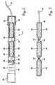
- FIGURE 1 illustrates a fuel storage tank 10 in combination with an interior 14 and an exterior 24 galvanic anode assembly formed in accordance with the present invention.
- the fuel storage tank 10 shown is a cylindrical fuel storage tank formed of metal, such as iron, and is typical of the type of underground fuel storage tanks used to store fuel at service (i.e., gas) stations, etc.
- the storage tank 10 includes a venting tube 11 and a fuel filler tube 12 that extend upwardly from the fuel tank to the surface of the ground 20 in which the tank is buried.
- the invention is illustrated for use with underground fuel storage tanks, it may be used with either underground or above-ground fuel storage tanks. In addition, the invention may be used in tanks used to store substances other than fuel.
- Corrosion of the interior surface of the storage tank 10 is prevented by the interior galvanic anode assembly 14, which is placed inside the storage tank and electrically connected to the tank by an electrical cable 16. More specifically, one end of the cable 16 is connected to one end of the galvanic anode assembly 14. The other end of the cable is electrically connected to a metal tube 17.
- the tube 17 passes through the filler tube 12 extending from the top of the fuel filler tube 12 downward at least partially into the interior of the tank 10.
- the tube 17 is electrically conductive and is electrically connected to the storage tank 10 by being connected to the filler tube 12.
- the galvanic anode assembly is sized to be inserted into the tank 10 via the filler tube 12.
- the electrical cable 16 is long enough to allow the galvanic anode assembly 14 to be lowered to the bottom of the tank and to lie along the bottom, as shown.
- the external anode assembly 24 is buried below the surface of the ground 20 in the proximity of the storage tank.
- one end of the exterior anode assembly 24 is connected by electrical cable 22 to one terminal of an option DC power supply 18.
- the other terminal of the DC power supply 18 is in turn electrically connected to the exterior surface of the tank 10 by an electrical cable 23 connected to filler tube 12.
- the exterior anode assembly 24 helps to prevent corrosion of the exterior of the tank 10.
- the internal galvanic anode assembly 14 includes one or more sacrificial anode elements 36 that are electrically connected to the cable 16. More specifically the anode elements 36 are electrically connected in series by connecting cables 19, as shown in FIGURE 2. One of the outer anode elements 36 of the series is electrically connected to one end of the cable 16.
- the number of anode elements 36 used, and the size and shape of the anode elements, are determined by the geometry of a protective container 28 (described below) in which they are placed and the geometry of the fuel tank 10 in which the galvanic anode assembly 14 is used.
- Each anode element 36 is surrounded by a layer of hydrophilic material 38. Since hydrophilic material absorbs water, the layer of hydrophilic material 38 maintains a layer of water around the anode elements 36 if there is any water in the interior of the tank 10. The layer of water in the hydrophilic material 38 around the anode elements 36 establishes a low-resistance electrically conductive pathway between the anode elements 36, the water surrounding the galvanic anode assembly 14, and the interior surface of the fuel tank 10.
- the hydrophilic material consists of 99.5% polyacrylamide and less than .05% acrylamide.
- One exemplary hydrophilic gel is sold under the trade name Terr Sorb Ag by Industrial Services International, Inc.
- the water absorbed by the hydrophilic material 38 creates an electrolyte around the anode elements 36.
- the hydrophilic material 38 also helps to absorb metal ions produced as the anode elements 36 are consumed. As a result, the metal ions do not combine with water to form corrosive salts that can enter and contaminate fuel within the tank 10.
- hydrophilic materials having different amounts of polyacrylamide or other hydrophilic materials may be used.
- the chosen hydrophilic material should absorb water to remove the water from contact with the metal interior surface of the tank and lower the resistivity around the sacrificial anode. It is also advantageous that the hydrophilic material absorb the metal ions produced as the anode elements are consumed.
- the anode elements 36 are, of course, formed of a metal that is higher on the electromotive scale, i.e., higher Electromotive Force than the metal used to form the tank 10. If the tank is formed of a ferrous material, suitable metals for forming the anode elements include zinc and magnesium.
- the hydrophilic material 38 is maintained around each anode element 36 by a porous container or bag 40 that surrounds each anode element 36.
- the bags 40 are formed of a porous material that allows water to pass through the bags into the hydrophilic material 38, but prevents the hydrophilic material from moving through the bag 40 and contaminating fuel within the storage tank 10.
- the entire structure consisting of anode elements 36, hydrophilic material 38, and porous bags 40 is contained in a protective container 28.
- the protective container 28 is cylindrical and includes two endcaps 32 and 34 that maintain the anode elements 36 within the interior of the container 28.
- the protective container 28 includes a plurality of holes, preferably in the form of slots 30 spaced along its length. The slots 30 allow water and fuel to enter the interior of the container 28 while maintaining the anode elements 36 and bags 40 within the container.
- the container 28 may be formed from a wide variety of different materials, however, it is advantageous for the container to be formed of a flexible electrically insulating material, such as a plastic or rubber tube. Forming the container 28 of a flexible material and maintaining the length of each individual anode element 36 relatively short allows the entire anode assembly 14 to be flexible over its length. A flexible anode 14 is easier to insert through the fuel filler tube 12 into the fuel storage tank 10 than is a rigid assembly.
- the container 28 In addition to protecting the anode elements 36, bags 40, and hydrophilic gel 38 from damage during insertion or withdrawal, the container 28 also prevents the anode elements 36 from directly contacting the interior of the storage tank 10. This ensures that an electrical connection is not established directly between the interior of the fuel storage tank 10 and the anode elements 36. The container 28 also prevents any water within the hydrophilic gel 38 from contacting the metal interior surface of the tank, thus helping to prevent corrosion.
- the tube 17 is first withdrawn from the storage tank.
- the anode 14 is then electrically connected to the tube 17 by cable 16 and lowered into the storage tank through the filler tube 12.
- it is withdrawn through the filler tube 12.
- anode assembly 14 be placed adjacent the bottom of the tank 10.
- water is lighter than the fuel that accumulates at the bottom of the tank. Placing the anode assembly 14 at the bottom of the tank ensures that the hydrophilic gel will absorb water within the bottom of the tank, thus removing the water from contact with the metal interior surface of the tank.
- FIGURE 3 A second embodiment of the porous bag 40 is illustrated in FIGURE 3.
- a continuous bag is placed over all of the anode elements 36.
- the portions of the bag 40 located between individual anode elements 36 are tied off using ties 42 to establish individual sealed compartments around each anode element 36.
- it is preferred to maintain individual compartments around each anode element 36 to ensure that hydrophilic material 38 surrounds each anode element 36 alternate configurations can be used.
- a single, undivided bag could surround all the anode elements 36.
- the bag 40 could be eliminated altogether, and the interior of the container 28 could be filled with a hydrophilic material.
- the size of the holes or slots 30 and size of hydrophilic material 38 would have to be tailored to ensure that the hydrophilic material does not pass through the slots 30 and contaminate fuel within the storage tank 10.
- the structure of the external anode assembly 24 shown in FIGURE 1, could be the same as the structure of the interior anode assembly 14 described above.
- the anode assembly 24 could be of existing anode designs.
- the efficiency of the anode assembly 24 is increased by surrounding the anode with a hydrophilic gel 26, such as a polyacrylamide material in a gel or crystal form.
- the hydrophilic gel 26 could be mixed with the soil surrounding the anode assembly 24, for example.
- the surrounding soil will act as a container that maintains the hydrophilic gel around the anode assembly 24.
- the hydrophilic gel could be contained around the exterior anode assembly 24 through the use of a porous bag (not shown) in a manner similar to that described with respect to the interior anode assembly 14 described above.
- the hydrophilic gel 26 surrounding the anode assembly 24 absorbs and holds water within the soil in the vicinity of the anode. As the hydrophilic gel 26 absorbs water, it creates an improved electrolyte and ensures an efficient low-resistance electrical path between the anode assembly 24 and the surrounding soil.
- the hydrophilic gel provides the anode assembly 24 with a uniform environment for low-resistance contact to the earth, thus increasing the efficiency of the electrical path.
- The, exterior anode assembly 24 may be connected in a galvanic protection configuration or an impressed current configuration. In a galvanic configuration, the anode assembly is directly electrically connected (not shown) to the exterior of the storage tank 10 using an electrical cable or other means.
- the efficiency of the exterior anode assembly 24 may be increased by connecting it to an optional DC power source 18 in an impressed current configuration, as shown in FIGURE 1.
- the power source 18 is in turn electrically connected to the storage tank 10 through the use of an electrical cable 23 as described above.
- the power source 18 provides a driving force that helps move current between the anode assembly 24 and the exterior surface of the storage tank 10.
- the current provided by the power source assists in moving current between the anode assembly 24 and exterior surface of the storage tank 10, thus ensuring that the anode 24 corrodes and is consumed as opposed to the exterior surface of the storage tank.
- the anode elements 36 could be formed of other materials than those described above.
- hydrophilic materials other than those specifically described above can be used.
- geometry of and materials used to form the container 28 can also be altered without departing from the invention.
- the container 28 can be eliminated altogether and other methods used to prevent the anode elements 36 and hydrophilic material from contacting the interior of the tank 10.
Landscapes
- Chemical & Material Sciences (AREA)
- Engineering & Computer Science (AREA)
- Materials Engineering (AREA)
- Mechanical Engineering (AREA)
- Metallurgy (AREA)
- Organic Chemistry (AREA)
- Prevention Of Electric Corrosion (AREA)
- Preventing Corrosion Or Incrustation Of Metals (AREA)
- Secondary Cells (AREA)
Claims (9)
- Système de contrôle de la corrosion anodique hydrophile comportant :un réservoir de stockage de pétrole, etune anode positionnée au fond de la partie intérieure du réservoir de stockage et reliée électriquement au réservoir de stockage, l'anode incluant au moins un élément anodique sacrificiel, un gel hydrophile entourant l'élément anodique, et un conteneur poreux entourant le gel hydrophile et l'élément anodique afin de maintenir le gel hydrophile autour de l'élément anodique et afin de permettre au liquide contenu dans le réservoir de stockage de traverser le conteneur pour venir en contact avec le gel hydrophile de manière à permettre au gel hydrophile d'absorber l'eau présente dans le réservoir de stockage, le conteneur poreux empêchant tout contact entre l'élément anodique et l'intérieur du réservoir de stockage.
- Système selon la revendication 1, dans lequel le gel hydrophile et formé, au moins partiellement, de polyacrylamide.
- Système selon la revendication 1, dans lequel le conteneur poreux inclut un sac poreux qui entoure le gel hydrophile et l'élément anodique et un tube souple poreux qui entoure le sac poreux.
- Système selon la revendication 3, dans lequel le tube souple est formé d'un matériau électriquement isolant et dans lequel le tube est souple sur toute sa longueur afin de permettre à l'anode d'être insérée dans le réservoir de stockage à travers une ouverture d'accès du réservoir de stockage ou d'en être retirée.
- Système de contrôle de la corrosion anodique hydrophile comportant :
une anode adaptée pour être insérée dans une ouverture d'accès d'un réservoir de stockage de carburant et reliée électriquement au réservoir de stockage de carburant, l'anode incluant au moins un élément anodique sacrificiel, un gel de polyacrylamide hydrophile entourant l'élément anodique, et un conteneur poreux entourant le gel de polyacrylamide hydrophile et l'élément anodique, le conteneur poreux maintenant le gel de polyacrylamide hydrophile autour de l'élément anodique tout en permettant au liquide contenu dans le réservoir de stockage de traverser le conteneur poreux et de venir en contact avec le gel de polyacrylamide hydrophile afin de permettre au gel de polyacrylamide hydrophile d'absorber l'eau contenue dans le réservoir de stockage, la structure transversale du conteneur poreux maintenant l'élément anodique hors de contact avec le réservoir de stockage de carburant et la structure longitudinale du conteneur poreux étant suffisamment souple, sur toute sa longueur, pour permettre à l'anode d'être insérée à travers l'ouverture d'accès du réservoir de stockage de carburant et d'en être retirée. - Système selon la revendication 5, dans lequel le conteneur poreux inclut un sac poreux entourant le gel de polyacrylamide hydrophile et un tube souple entourant le sac poreux, le tube souple étant formé d'un matériau électriquement isolant.
- Procédé pour absorber l'eau contenue dans un réservoir de stockage de pétrole et réduire la corrosion du réservoir de stockage de pétrole, le procédé consistant à :placer un gel hydrophile autour d'au moins un élément anodique sacrificiel,entourer le gel hydrophile et l'élément anodique d'un conteneur poreux qui maintient le gel hydrophile autour de l'élément anodique, mais permet au liquide contenu dans le réservoir de stockage de traverser le conteneur poreux pour venir en contact avec le gel hydrophile afin de former une anode hydrophile,insérer l'anode hydrophile à l'intérieur du réservoir de stockage à travers une ouverture d'accès du réservoir de stockage de sorte que l'anode hydrophile soit positionnée à proximité adjacente du fond du réservoir de stockage, et de manière à ce que le gel hydrophile absorbe l'eau se trouvant au fond du réservoir de stockage, etrelier électriquement l'élément anodique au réservoir de stockage.
- Procédé selon la revendication 7, consistant en outre à entourer le gel hydrophile et l'élément anodique d'un conteneur poreux possédant une structure transversale qui maintient l'élément anodique hors de contact avec le fond du réservoir de stockage de carburant et une structure longitudinale qui est suffisamment souple, sur toute sa longueur, pour permettre à l'anode hydrophile d'être insérée dans le réservoir de stockage à travers l'ouverture d'accès du réservoir de stockage et d'en être retirée.
- Procédé selon la revendication 8, consistant en outre à encapsuler le gel hydrophile et l'élément anodique dans un sac poreux et à entourer le sac poreux d'un conteneur poreux qui est souple sur toute sa longueur.
Applications Claiming Priority (3)
| Application Number | Priority Date | Filing Date | Title |
|---|---|---|---|
| US08/347,041 US5505826A (en) | 1994-11-30 | 1994-11-30 | Hydrophilic anode corrosion control system |
| US347041 | 1994-11-30 | ||
| PCT/US1995/015596 WO1996018092A2 (fr) | 1994-11-30 | 1995-11-30 | Systeme hydrophile de prevention de la corrosion anodique |
Publications (3)
| Publication Number | Publication Date |
|---|---|
| EP0796357A1 EP0796357A1 (fr) | 1997-09-24 |
| EP0796357A4 EP0796357A4 (fr) | 1998-02-25 |
| EP0796357B1 true EP0796357B1 (fr) | 2001-07-11 |
Family
ID=23362076
Family Applications (1)
| Application Number | Title | Priority Date | Filing Date |
|---|---|---|---|
| EP95943635A Expired - Lifetime EP0796357B1 (fr) | 1994-11-30 | 1995-11-30 | Systeme hydrophile de prevention de la corrosion anodique |
Country Status (11)
| Country | Link |
|---|---|
| US (1) | US5505826A (fr) |
| EP (1) | EP0796357B1 (fr) |
| AT (1) | ATE203065T1 (fr) |
| AU (1) | AU4505796A (fr) |
| CA (1) | CA2206428C (fr) |
| DE (1) | DE69521715T2 (fr) |
| DK (1) | DK0796357T3 (fr) |
| ES (1) | ES2158148T3 (fr) |
| GR (1) | GR3036797T3 (fr) |
| PT (1) | PT796357E (fr) |
| WO (1) | WO1996018092A2 (fr) |
Cited By (1)
| Publication number | Priority date | Publication date | Assignee | Title |
|---|---|---|---|---|
| WO2023094820A3 (fr) * | 2021-11-26 | 2024-03-28 | C-Probe Systems Limited | Protection de corps structuraux renforcés |
Families Citing this family (18)
| Publication number | Priority date | Publication date | Assignee | Title |
|---|---|---|---|---|
| US6033553A (en) * | 1996-10-11 | 2000-03-07 | Bennett; Jack E. | Cathodic protection system |
| US6471851B1 (en) * | 1996-10-11 | 2002-10-29 | Jack E. Bennett | Cathodic protection system |
| US5968339A (en) * | 1997-08-28 | 1999-10-19 | Clear; Kenneth C. | Cathodic protection system for reinforced concrete |
| WO1999018261A1 (fr) * | 1997-10-02 | 1999-04-15 | Fluor Daniel, Inc. | Procedes et appareil de protection cathodique |
| US6224743B1 (en) * | 1998-02-06 | 2001-05-01 | Fluor Daniel, Inc. | Cathodic protection methods and apparatus |
| US6165346A (en) | 1999-02-05 | 2000-12-26 | Whitmore; David | Cathodic protection of concrete |
| US7276144B2 (en) * | 1999-02-05 | 2007-10-02 | David Whitmore | Cathodic protection |
| US6331242B1 (en) | 1999-12-06 | 2001-12-18 | United States Pipe And Foundry Company, Inc. | Anodic encasement corrosion protection system for underground storage tanks, and metallic components thereof |
| US6214203B1 (en) | 1999-12-06 | 2001-04-10 | United States Pipe Foundry | Anodic encasement corrosion protection system for pipe and appurtenances, and metallic components thereof |
| US6770177B2 (en) * | 2001-11-07 | 2004-08-03 | Ingersoll-Rand Company | Cathodic protection system for air compressor tanks |
| US7409589B2 (en) * | 2005-05-27 | 2008-08-05 | International Business Machines Corporation | Method and apparatus for reducing number of cycles required to checkpoint instructions in a multi-threaded processor |
| US7235961B1 (en) * | 2006-03-31 | 2007-06-26 | Ulc Robotics, Inc. | Method for managing corrosion of an underground structure |
| FR2986241B1 (fr) * | 2012-02-01 | 2014-02-21 | Alstom Hydro France | Dispositif de protection cathodique d'une paroi metallique contre la corrosion dans un milieu salin |
| US9410253B2 (en) * | 2013-03-15 | 2016-08-09 | Matcor, Inc. | Anode assembly with sand backfill for cathodic protection systems and method of installing the same for above ground storage tank applications |
| US9499915B2 (en) * | 2013-03-15 | 2016-11-22 | Saudi Arabian Oil Company | Encapsulated impressed current anode for vessel internal cathodic protection |
| US9550247B2 (en) | 2013-07-18 | 2017-01-24 | Aps Materials, Inc. | Double coupon reference cell and methods of making same |
| US9850584B2 (en) * | 2014-06-23 | 2017-12-26 | Matcor, Inc. | Anode assembly with reduced attenuation properties for cathodic protection systems |
| US20200248319A1 (en) * | 2019-02-04 | 2020-08-06 | Saudi Arabian Oil Company | Integrated Impressed Current Cathodic Protection for Wet Crude Handling Vessels |
Family Cites Families (19)
| Publication number | Priority date | Publication date | Assignee | Title |
|---|---|---|---|---|
| BE340855A (fr) * | 1926-06-15 | |||
| US2495466A (en) * | 1947-07-31 | 1950-01-24 | Dow Chemical Co | Packaged magnesium anode with cemented backfill |
| US2810690A (en) * | 1950-08-28 | 1957-10-22 | Houston Oil Field Mat Co Inc | Anode backfill |
| US3649492A (en) * | 1966-06-14 | 1972-03-14 | Union Oil Co | Method for determining the completeness of cathodic protection of corrodible metal structure |
| US3616421A (en) * | 1969-03-17 | 1971-10-26 | Atlantic Richfield Co | Sacrifical anode construction |
| US3887449A (en) * | 1973-05-21 | 1975-06-03 | Chromalloy American Corp | Coating method and composition for the sacrificial protection of metal substrates |
| JPS53934B2 (fr) * | 1974-05-10 | 1978-01-13 | ||
| US4133737A (en) * | 1977-06-27 | 1979-01-09 | Exxon Research & Engineering Co. | Shielded anodes |
| US4318787A (en) * | 1980-02-22 | 1982-03-09 | Conoco Inc. | Sacrificial anode composition in cathodic protection process |
| US4435263A (en) * | 1982-03-01 | 1984-03-06 | The Dow Chemical Company | Backfill for magnesium galvanic anodes |
| US4623435A (en) * | 1983-09-01 | 1986-11-18 | Columbia Gas System Service Corporation | Backfill for magnesium anodes |
| WO1988000700A1 (fr) * | 1986-07-10 | 1988-01-28 | Terumo Kabushiki Kaisha | Electrode de reference |
| US4980043A (en) * | 1986-12-11 | 1990-12-25 | Horiba, Ltd. | Reference electrode |
| US4861449A (en) * | 1988-02-08 | 1989-08-29 | St Onge Hank | Composite anode |
| US5167785A (en) * | 1989-10-07 | 1992-12-01 | Mccready David F | Thin electrodes |
| US5040599A (en) * | 1989-12-04 | 1991-08-20 | Phillips Petroleum Company | Cathodic protection |
| US5080773A (en) * | 1990-05-11 | 1992-01-14 | Cathodic Engineering Equipment Co., Inc. | Ground electrode backfill |
| US5316641A (en) * | 1992-12-16 | 1994-05-31 | Robert L. Wright | Storage tank internal corrosion prevention anode apparatus and method |
| CN1074785A (zh) * | 1993-03-10 | 1993-07-28 | 北京化工学院 | 一种化学降阻接地方法 |
-
1994
- 1994-11-30 US US08/347,041 patent/US5505826A/en not_active Expired - Fee Related
-
1995
- 1995-11-30 PT PT95943635T patent/PT796357E/pt unknown
- 1995-11-30 AU AU45057/96A patent/AU4505796A/en not_active Abandoned
- 1995-11-30 CA CA002206428A patent/CA2206428C/fr not_active Expired - Fee Related
- 1995-11-30 DK DK95943635T patent/DK0796357T3/da active
- 1995-11-30 DE DE69521715T patent/DE69521715T2/de not_active Expired - Fee Related
- 1995-11-30 WO PCT/US1995/015596 patent/WO1996018092A2/fr active IP Right Grant
- 1995-11-30 ES ES95943635T patent/ES2158148T3/es not_active Expired - Lifetime
- 1995-11-30 EP EP95943635A patent/EP0796357B1/fr not_active Expired - Lifetime
- 1995-11-30 AT AT95943635T patent/ATE203065T1/de not_active IP Right Cessation
-
2001
- 2001-10-04 GR GR20010401659T patent/GR3036797T3/el not_active IP Right Cessation
Cited By (1)
| Publication number | Priority date | Publication date | Assignee | Title |
|---|---|---|---|---|
| WO2023094820A3 (fr) * | 2021-11-26 | 2024-03-28 | C-Probe Systems Limited | Protection de corps structuraux renforcés |
Also Published As
| Publication number | Publication date |
|---|---|
| DE69521715D1 (de) | 2001-08-16 |
| CA2206428A1 (fr) | 1996-06-13 |
| US5505826A (en) | 1996-04-09 |
| CA2206428C (fr) | 2001-01-16 |
| GR3036797T3 (en) | 2002-01-31 |
| WO1996018092A2 (fr) | 1996-06-13 |
| ES2158148T3 (es) | 2001-09-01 |
| WO1996018092A3 (fr) | 1996-09-19 |
| PT796357E (pt) | 2001-12-28 |
| DK0796357T3 (da) | 2001-09-24 |
| EP0796357A1 (fr) | 1997-09-24 |
| DE69521715T2 (de) | 2002-07-04 |
| EP0796357A4 (fr) | 1998-02-25 |
| AU4505796A (en) | 1996-06-26 |
| ATE203065T1 (de) | 2001-07-15 |
Similar Documents
| Publication | Publication Date | Title |
|---|---|---|
| EP0796357B1 (fr) | Systeme hydrophile de prevention de la corrosion anodique | |
| US6346188B1 (en) | Battery-powered cathodic protection system | |
| US2565544A (en) | Cathodic protection and underground metallic structure embodying the same | |
| JPS624835B2 (fr) | ||
| KR20010030856A (ko) | 음극 보호 방법 및 장치 | |
| WO1998018980A1 (fr) | Electrodes pour systemes de protection electrochimique contre la corrosion | |
| US4874487A (en) | Corrosion protection | |
| US7182852B2 (en) | Cryogenic tank testing method including cathodic protection | |
| US6120675A (en) | Electrochemical method and electrode | |
| US4133737A (en) | Shielded anodes | |
| CA2606671C (fr) | Dispositif et technique de protection cathodique | |
| US20090205951A1 (en) | Corrosion control of bottom plates in above-ground storage tanks | |
| Kroon et al. | Cathodic protection of aboveground storage tank bottoms | |
| Nagy et al. | Developed software for cathodic protection of storage tanks | |
| US5527440A (en) | Repair of damaged electrode in impressed current corrosion protection system | |
| CA1330318C (fr) | Protection cathodique de fonds de reservoir de stockage | |
| US20020096438A1 (en) | Method and apparatus for cathodically protecting reinforced concrete structures | |
| EP0253671A2 (fr) | Protection contre la corrosion | |
| KR20000000726A (ko) | 해수용 배관의 갈바닉 부식 제어 방법 | |
| JPS5913082A (ja) | 屋外地上タンク底板外面の防食方法 | |
| SU359305A1 (ru) | Устройство для катодной защиты внутренней | |
| Bohnes et al. | Impressed Current Anodes | |
| KR20080013171A (ko) | 저장탱크와 이에 마련되는 바닥구조 및 저장탱크바닥구조의 보수방법 | |
| Huck | Cathodic Protection for Underground Piping in Power Plants | |
| Mohr | Cathodic protection for the bottoms of above ground storage tanks |
Legal Events
| Date | Code | Title | Description |
|---|---|---|---|
| PUAI | Public reference made under article 153(3) epc to a published international application that has entered the european phase |
Free format text: ORIGINAL CODE: 0009012 |
|
| 17P | Request for examination filed |
Effective date: 19970619 |
|
| AK | Designated contracting states |
Kind code of ref document: A1 Designated state(s): AT BE CH DE DK ES FR GB GR IE IT LI LU MC NL PT SE |
|
| A4 | Supplementary search report drawn up and despatched |
Effective date: 19980112 |
|
| AK | Designated contracting states |
Kind code of ref document: A4 Designated state(s): AT BE CH DE DK ES FR GB GR IE IT LI LU MC NL PT SE |
|
| 17Q | First examination report despatched |
Effective date: 19981211 |
|
| RAP1 | Party data changed (applicant data changed or rights of an application transferred) |
Owner name: LH TECHNOLOGY, INC. |
|
| RIN1 | Information on inventor provided before grant (corrected) |
Inventor name: ELL, STUART J. Inventor name: HAGLIN, PATRICK G. |
|
| GRAG | Despatch of communication of intention to grant |
Free format text: ORIGINAL CODE: EPIDOS AGRA |
|
| GRAG | Despatch of communication of intention to grant |
Free format text: ORIGINAL CODE: EPIDOS AGRA |
|
| GRAH | Despatch of communication of intention to grant a patent |
Free format text: ORIGINAL CODE: EPIDOS IGRA |
|
| GRAH | Despatch of communication of intention to grant a patent |
Free format text: ORIGINAL CODE: EPIDOS IGRA |
|
| GRAA | (expected) grant |
Free format text: ORIGINAL CODE: 0009210 |
|
| AK | Designated contracting states |
Kind code of ref document: B1 Designated state(s): AT BE CH DE DK ES FR GB GR IE IT LI LU MC NL PT SE |
|
| REF | Corresponds to: |
Ref document number: 203065 Country of ref document: AT Date of ref document: 20010715 Kind code of ref document: T |
|
| REG | Reference to a national code |
Ref country code: CH Ref legal event code: NV Representative=s name: E. BLUM & CO. PATENTANWAELTE Ref country code: CH Ref legal event code: EP |
|
| REF | Corresponds to: |
Ref document number: 69521715 Country of ref document: DE Date of ref document: 20010816 |
|
| REG | Reference to a national code |
Ref country code: IE Ref legal event code: FG4D |
|
| REG | Reference to a national code |
Ref country code: ES Ref legal event code: FG2A Ref document number: 2158148 Country of ref document: ES Kind code of ref document: T3 |
|
| ET | Fr: translation filed | ||
| REG | Reference to a national code |
Ref country code: DK Ref legal event code: T3 |
|
| ITF | It: translation for a ep patent filed | ||
| PGFP | Annual fee paid to national office [announced via postgrant information from national office to epo] |
Ref country code: IE Payment date: 20011128 Year of fee payment: 7 |
|
| PGFP | Annual fee paid to national office [announced via postgrant information from national office to epo] |
Ref country code: DK Payment date: 20011129 Year of fee payment: 7 |
|
| PGFP | Annual fee paid to national office [announced via postgrant information from national office to epo] |
Ref country code: SE Payment date: 20011130 Year of fee payment: 7 Ref country code: PT Payment date: 20011130 Year of fee payment: 7 Ref country code: MC Payment date: 20011130 Year of fee payment: 7 Ref country code: GR Payment date: 20011130 Year of fee payment: 7 |
|
| PGFP | Annual fee paid to national office [announced via postgrant information from national office to epo] |
Ref country code: LU Payment date: 20011205 Year of fee payment: 7 |
|
| PGFP | Annual fee paid to national office [announced via postgrant information from national office to epo] |
Ref country code: BE Payment date: 20011210 Year of fee payment: 7 |
|
| PGFP | Annual fee paid to national office [announced via postgrant information from national office to epo] |
Ref country code: CH Payment date: 20011212 Year of fee payment: 7 |
|
| PGFP | Annual fee paid to national office [announced via postgrant information from national office to epo] |
Ref country code: ES Payment date: 20011226 Year of fee payment: 7 |
|
| REG | Reference to a national code |
Ref country code: PT Ref legal event code: SC4A Free format text: AVAILABILITY OF NATIONAL TRANSLATION Effective date: 20010926 |
|
| REG | Reference to a national code |
Ref country code: GB Ref legal event code: IF02 |
|
| REG | Reference to a national code |
Ref country code: GR Ref legal event code: EP Ref document number: 20010401659 Country of ref document: GR |
|
| PLBE | No opposition filed within time limit |
Free format text: ORIGINAL CODE: 0009261 |
|
| STAA | Information on the status of an ep patent application or granted ep patent |
Free format text: STATUS: NO OPPOSITION FILED WITHIN TIME LIMIT |
|
| 26N | No opposition filed | ||
| PGFP | Annual fee paid to national office [announced via postgrant information from national office to epo] |
Ref country code: AT Payment date: 20021122 Year of fee payment: 8 |
|
| PGFP | Annual fee paid to national office [announced via postgrant information from national office to epo] |
Ref country code: GB Payment date: 20021128 Year of fee payment: 8 |
|
| PGFP | Annual fee paid to national office [announced via postgrant information from national office to epo] |
Ref country code: FR Payment date: 20021129 Year of fee payment: 8 |
|
| PG25 | Lapsed in a contracting state [announced via postgrant information from national office to epo] |
Ref country code: LU Free format text: LAPSE BECAUSE OF NON-PAYMENT OF DUE FEES Effective date: 20021130 Ref country code: LI Free format text: LAPSE BECAUSE OF NON-PAYMENT OF DUE FEES Effective date: 20021130 Ref country code: CH Free format text: LAPSE BECAUSE OF NON-PAYMENT OF DUE FEES Effective date: 20021130 Ref country code: BE Free format text: LAPSE BECAUSE OF NON-PAYMENT OF DUE FEES Effective date: 20021130 |
|
| PGFP | Annual fee paid to national office [announced via postgrant information from national office to epo] |
Ref country code: NL Payment date: 20021130 Year of fee payment: 8 |
|
| PG25 | Lapsed in a contracting state [announced via postgrant information from national office to epo] |
Ref country code: SE Free format text: LAPSE BECAUSE OF NON-PAYMENT OF DUE FEES Effective date: 20021201 Ref country code: ES Free format text: LAPSE BECAUSE OF NON-PAYMENT OF DUE FEES Effective date: 20021201 |
|
| PG25 | Lapsed in a contracting state [announced via postgrant information from national office to epo] |
Ref country code: IE Free format text: LAPSE BECAUSE OF NON-PAYMENT OF DUE FEES Effective date: 20021202 |
|
| PGFP | Annual fee paid to national office [announced via postgrant information from national office to epo] |
Ref country code: DE Payment date: 20021223 Year of fee payment: 8 |
|
| PG25 | Lapsed in a contracting state [announced via postgrant information from national office to epo] |
Ref country code: DK Free format text: LAPSE BECAUSE OF NON-PAYMENT OF DUE FEES Effective date: 20021231 |
|
| BERE | Be: lapsed |
Owner name: *LH TECHNOLOGY INC. Effective date: 20021130 |
|
| PG25 | Lapsed in a contracting state [announced via postgrant information from national office to epo] |
Ref country code: PT Free format text: LAPSE BECAUSE OF NON-PAYMENT OF DUE FEES Effective date: 20030531 |
|
| PG25 | Lapsed in a contracting state [announced via postgrant information from national office to epo] |
Ref country code: MC Free format text: LAPSE BECAUSE OF NON-PAYMENT OF DUE FEES Effective date: 20030601 |
|
| PG25 | Lapsed in a contracting state [announced via postgrant information from national office to epo] |
Ref country code: GR Free format text: LAPSE BECAUSE OF NON-PAYMENT OF DUE FEES Effective date: 20030609 |
|
| REG | Reference to a national code |
Ref country code: DK Ref legal event code: EBP |
|
| REG | Reference to a national code |
Ref country code: CH Ref legal event code: PL |
|
| EUG | Se: european patent has lapsed | ||
| REG | Reference to a national code |
Ref country code: PT Ref legal event code: MM4A Free format text: LAPSE DUE TO NON-PAYMENT OF FEES Effective date: 20030531 |
|
| REG | Reference to a national code |
Ref country code: IE Ref legal event code: MM4A |
|
| PG25 | Lapsed in a contracting state [announced via postgrant information from national office to epo] |
Ref country code: GB Free format text: LAPSE BECAUSE OF NON-PAYMENT OF DUE FEES Effective date: 20031130 Ref country code: AT Free format text: LAPSE BECAUSE OF NON-PAYMENT OF DUE FEES Effective date: 20031130 |
|
| REG | Reference to a national code |
Ref country code: ES Ref legal event code: FD2A Effective date: 20031213 |
|
| PG25 | Lapsed in a contracting state [announced via postgrant information from national office to epo] |
Ref country code: NL Free format text: LAPSE BECAUSE OF NON-PAYMENT OF DUE FEES Effective date: 20040601 |
|
| PG25 | Lapsed in a contracting state [announced via postgrant information from national office to epo] |
Ref country code: DE Free format text: LAPSE BECAUSE OF NON-PAYMENT OF DUE FEES Effective date: 20040602 |
|
| GBPC | Gb: european patent ceased through non-payment of renewal fee |
Effective date: 20031130 |
|
| PG25 | Lapsed in a contracting state [announced via postgrant information from national office to epo] |
Ref country code: FR Free format text: LAPSE BECAUSE OF NON-PAYMENT OF DUE FEES Effective date: 20040730 |
|
| NLV4 | Nl: lapsed or anulled due to non-payment of the annual fee |
Effective date: 20040601 |
|
| REG | Reference to a national code |
Ref country code: FR Ref legal event code: ST |
|
| PG25 | Lapsed in a contracting state [announced via postgrant information from national office to epo] |
Ref country code: IT Free format text: LAPSE BECAUSE OF NON-PAYMENT OF DUE FEES;WARNING: LAPSES OF ITALIAN PATENTS WITH EFFECTIVE DATE BEFORE 2007 MAY HAVE OCCURRED AT ANY TIME BEFORE 2007. THE CORRECT EFFECTIVE DATE MAY BE DIFFERENT FROM THE ONE RECORDED. Effective date: 20051130 |