EP0795884A2 - Pressure switch - Google Patents
Pressure switch Download PDFInfo
- Publication number
- EP0795884A2 EP0795884A2 EP97103153A EP97103153A EP0795884A2 EP 0795884 A2 EP0795884 A2 EP 0795884A2 EP 97103153 A EP97103153 A EP 97103153A EP 97103153 A EP97103153 A EP 97103153A EP 0795884 A2 EP0795884 A2 EP 0795884A2
- Authority
- EP
- European Patent Office
- Prior art keywords
- spider
- force
- pressure switch
- switch
- switches
- Prior art date
- Legal status (The legal status is an assumption and is not a legal conclusion. Google has not performed a legal analysis and makes no representation as to the accuracy of the status listed.)
- Granted
Links
Images


Classifications
-
- H—ELECTRICITY
- H01—ELECTRIC ELEMENTS
- H01H—ELECTRIC SWITCHES; RELAYS; SELECTORS; EMERGENCY PROTECTIVE DEVICES
- H01H35/00—Switches operated by change of a physical condition
- H01H35/24—Switches operated by change of fluid pressure, by fluid pressure waves, or by change of fluid flow
- H01H35/26—Details
- H01H35/2657—Details with different switches operated at substantially different pressures
- H01H35/2664—Details with different switches operated at substantially different pressures making use of a balance plate pivoting about different axes
Definitions
- the invention relates to a pressure switch with at least one switch that can be actuated against a pretensioning force, a spider having two or more lever arms, into which a force is introduced in a first direction in order to use the lever arms to overcome the pretensioning force as a function of the switch or switches The magnitude of the force introduced and thus to be operated selectively depending on the pressure.
- Such pressure switches for example known from EP 0 347 904 B1, are also referred to as "pressure monitors". They serve to actuate at least one, usually two or more electrical switches depending on a pressure to be monitored. If the pressure to be monitored increases, the switches are operated selectively one after the other at certain, preselected pressures. Such multiple pressure switches are usually operated with a membrane, i.e. the pressure to be monitored generates a force on the membrane with which the switches are actuated.
- Such membrane-operated switch arrangements in which switches, in particular pretensioned mechanical snap switches, for electrical signals or load currents depending on one pressure applied to the membrane are used in many practical applications to control and regulate devices such as washing machines and dishwashers.
- the membrane is loaded with a pressure that is derived from the water level in the working area of the device.
- the pressure switch acts as a "pressure switch” and measures the height of the water column in the machine.
- Switches are arranged in the lower housing part 10 (the individual switches are also referred to in the prior art as "switching systems”.
- the pressure acting on the membrane 16 from above is transmitted via the plate 14 and its central pin 22 into a recess 24 which is formed centrally in the spider 12.
- the depression 24 is therefore the location of the spider 12 at which a force corresponding to the membrane pressure is introduced into the spider 12.
- the spider 12 is supported on its underside at its lever arm ends (see also FIG. 2).
- the spider 12 is supported on the individual switches it actuates via mandrels 28 which protrude upward at the free ends of the switch springs 26 and each engage in a recess 30 at the end of a lever arm of the spider 12.
- a surface or a trench depending on the function, can also be provided.
- 1 shows a single switch I in the lower housing part 10 by way of example.
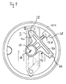
- FIG. 2 shows a top view of the lower housing part 10 with three switches I, II and III.
- Each switch is biased into a position according to FIG. 1 by means of a spring 32.
- the spring 32 thus acts as a compression spring. It presses the free end 38 of the switch spring 26 in FIG. 1 upward against a nose formed on the lower housing part 10.
- the lower part of the housing is made of plastic.
- the spreading force of the spring 32 is adjustable by means of a clamping screw 34.
- the switch contacts 40 to be switched are arranged.
- the switch spring 26 is clamped approximately in the middle at a point 42 and is designed such that when the spring end 38 moves downward in FIG. 1 against a stop 36, a contact body 44 moves from the upper to the lower contact of the switch contacts 40 and thus either a signal or a load current is also switched directly.
- load currents flow with a considerable current (for example 12 A or greater).
- the spider 12 distributes the force introduced centrally into the individual prestressed switches I, II and III via the mandrels 28a, 28b and 28c.
- the forces transmitted via the mandrels 28a, 28b and 28c are different.
- 43% of the force introduced into the spider 12 via the recess 24 is transmitted to the mandrel 28a of the switch I, while 33% of the force is applied to the mandrel 28b of the switch II and 24% of the force is applied to the Mandrel 28c of switch III are transmitted.
- FIG. 3 shows a pressure switch according to the prior art, in which only two switches I, III are provided instead of the three switches of FIG. 2.
- the arm 12b of the spider does not operate a switch. Instead, the outer end of the arm 12b is supported on a stop 54 which is fixedly connected to the housing 10. This support of the spider 12 is necessary because the recess 24, in which the force is introduced into the spider 12, does not lie on the connecting line 56 of those points at which the force is transmitted to the switches via the arms 12a, 12c, ie the connecting line between the pins 28a, 28c of the switches I, III.
- the force derived via the arm 12b is thus absorbed by the housing 10 and is not used to actuate a switch.
- the aim of the invention is to design the pressure switch described in the introduction in such a way that high actuation forces and the smallest hysteresis for the switches can be achieved without increasing the dimensions of the pressure switch even at relatively low pressures.
- the spider is designed according to the invention so that it is supported when switching with at least one lever arm in a direction which is at least approximately opposite to the direction in which the force is introduced into the spider.
- the spider has at least one lever arm which, when the force is introduced into the spider after overcoming a free distance, meets a stop which is fixedly connected to the housing of the switch, and thus the spider during the subsequent actuation of switches supported on this stop.
- a great versatility and adaptability of a given switch housing to different requirements with regard to the number and arrangement of the switches results in particular when the actuating force is introduced into the spider at a point which is at least approximately centric with respect to the force-generating, circular membrane.
- the supporting lever arm of the spider and the switch-actuating further lever arms are preferably arranged in relation to one another and to the point of force introduction into the spider that one or more one-sided levers are formed and so the actuating forces for the switches are significantly greater than those in the spider initiated force.
- the inventive concepts outlined above teach the use of a spider lever arm, with which the spider is supported in the opposite direction to the force application direction when actuating at least one switch.
- the geometry of the lever arms is chosen so that the above-mentioned goal of maximum force utilization is achieved.
- spiders of the type in question which have a lever arm which does not press a prestressed switch.
- the lever arms are not designed in the sense of the invention. They only serve to guide the spider and lift it immediately upon actuation of the spider, ie they do not absorb any forces in terms of supporting the spider according to the invention.
- the spider is designed so that the lever arm with which it is supported in the direction opposite to the force introduction direction is at least approximately at the location of the spider at which the actuating force is introduced into the spider.
- Other versions of the connection to the spider are possible.
- lever arms are mentioned above, this is to be understood functionally in relation to the acting force and torques and is not necessary in the sense of shaping elongated (thin) lever arms.
- the spider can also be a large, approximately plate-like structure. It is essential that the levers defined above are formed by the introduction of force into the spider on the one hand and the support points of the spider on the switches or the switch housing on the other hand.
- FIG. 4 shows a top view (corresponding to FIG. 2) of a first embodiment of a pressure switch according to the invention.
- the housing cover (FIG. 1, reference number 18), the membrane (FIG. 1, reference number 16) and the plate (FIG. 1, reference number 14) have been omitted, in order to look into the interior of the lower housing part 10 from above to release.
- the pressure switch is thus completed by adding a plate 14, a membrane 16 and a cover 18 according to FIG. 1.
- the resulting tilting moment on the spider 12 is absorbed by a further arm 12d, which deals with its supports radially outer end under a tab 58 protruding from the edge 10a of the lower housing part 10.
- a further arm 12d which deals with its supports radially outer end under a tab 58 protruding from the edge 10a of the lower housing part 10.
- the force distribution can be varied simply by varying the point at which the lever arm 12d is supported on the tab 58.
- Fig. 6 shows three modifications of the embodiment of FIG. 4, wherein different pairs of switches are actuated in pairs, namely the switch pairs I-II, I-III and II-III.
- the examples in FIG. 6 are self-explanatory on the basis of the above description and the reference numerals.
- FIG. 7 shows three modifications of the exemplary embodiment according to FIG. 5.
- the switch combinations I-II, I-III and II-III are actuated selectively, a fourth arm 12e being provided, which follows Overcoming a free distance "d" is supported on a stop 60 so that a relatively large force (corresponding to a high water column) is required to actuate the open switch, which has not yet been actuated.
- FIG. 8 shows a further pressure switch according to the invention, which differs from the exemplary embodiments according to FIGS. 5 and 7 in that the stop 60 there is replaced by a switch.
- all three switches I, II and III are depressed by a respective associated arm 12a, 12b or 12c of the spider 12 against a biasing force, depending on the force "M".
- a spider arm for example the arm 12b, is not yet supported on the associated mandrel 28b of the associated switch II. Rather, this arm must first overcome a distance "d” (analogue to FIG. 5, section A-B) until it strikes the mandrel 28b.
- switch I switches first and at the same time or shortly thereafter the previously free arm 12b is now supported on the associated mandrel 28b of switch II, so that switches II and III relatively high switching forces can be selected.
- Fig. 9 shows that the invention can also be used with a 1-fold pressure switch.
- the arm 12e of the spider 12 is supported on a stop 60 fixed to the housing, and the arm 12d of the spider 12 is again threaded under a tab 58 on the housing edge 10a.
- the only switch I is actuated by the arm 12a, with a relatively large switching force. This enables a pressure switch that is very small in size, the point at which the switching force is introduced into the switch I does not have to be centered.
- the invention enables both selective and simultaneous switching of switching systems.
Landscapes
- Physics & Mathematics (AREA)
- Fluid Mechanics (AREA)
- Switches Operated By Changes In Physical Conditions (AREA)
Abstract
Ein Druckschalter für zum Beispiel Wasch- oder Geschirrspülmaschinen soll in der Lage sein, zumindest einen Schalter sehr genau mit hoher Kraft bei nur geringen Drücken zu betätigen. Der membranbetätigte Druckschalter weist eine Spinne (12) auf mit Hebelarmen (12a), (12c) und (12d). Ein Hebelarm (12d) stützt die Spinne (12) bei Schalterbetätigung in einer Richtung ab, die zumindest annähernd der Richtung entgegengesetzt ist, in der die Spinne (12) durch eine Kraft (M) niedergedrückt wird.
Description
Die Erfindung betrifft einen Druckschalter mit mindestens einem gegen eine Vorspannkraft betätigbaren Schalter, einer zwei oder mehr Hebelarme aufweisenden Spinne, in die eine Kraft in einer ersten Richtung eingeleitet wird, um mittels der Hebelarme den bzw. die Schalter unter Überwindung der Vorspannkraft in Abhängigkeit von der Größe der eingeleiteten Kraft und damit in Abhängigkeit vom Druck selektiv zu betätigen.The invention relates to a pressure switch with at least one switch that can be actuated against a pretensioning force, a spider having two or more lever arms, into which a force is introduced in a first direction in order to use the lever arms to overcome the pretensioning force as a function of the switch or switches The magnitude of the force introduced and thus to be operated selectively depending on the pressure.
Solche zum Beispiel aus der EP 0 347 904 B1 bekannten Druckschalter werden auch als "Druckwächter" bezeichnet. Sie dienen dazu, in Abhängigkeit von einem zu überwachenden Druck zumindest einen, üblicherweise zwei oder mehr elektrische Schalter zu betätigen. Nimmt der zu überwachende Druck zu, werden bei bestimmten, vorgewählten Drücken die Schalter nacheinander selektiv betätigt. Üblicherweise werden solche Mehrfach-Druckschalter mit einer Membran betätigt, d.h. der zu überwachende Druck erzeugt an der Membran eine Kraft, mit der die Schalter betätigt werden.Such pressure switches, for example known from EP 0 347 904 B1, are also referred to as "pressure monitors". They serve to actuate at least one, usually two or more electrical switches depending on a pressure to be monitored. If the pressure to be monitored increases, the switches are operated selectively one after the other at certain, preselected pressures. Such multiple pressure switches are usually operated with a membrane, i.e. the pressure to be monitored generates a force on the membrane with which the switches are actuated.
Solche membranbetätigten Schalteranordnungen, bei denen Schalter, insbesondere vorgespannte mechanische Schnappschalter, für elektrische Signale oder Lastströme in Abhängigkeit von einem auf die Membran einwirkenden Druck betätigt werden, finden vielfache praktische Anwendung zur Steuerung und Regelung von Geräten, beispielsweise Wasch- und Geschirrspülmaschinen. Die Membran wird dabei mit einem Druck belastet, der vom Wasserstand im Arbeitsraum des Gerätes abgeleitet ist. Bei dieser Anwendung wirkt also der Druckschalter als "Druckwächter" und mißt die Höhe der Wassersäule in der Maschine.Such membrane-operated switch arrangements, in which switches, in particular pretensioned mechanical snap switches, for electrical signals or load currents depending on one pressure applied to the membrane are used in many practical applications to control and regulate devices such as washing machines and dishwashers. The membrane is loaded with a pressure that is derived from the water level in the working area of the device. In this application, the pressure switch acts as a "pressure switch" and measures the height of the water column in the machine.
Bei technisch fortschrittlichen Wasch- und Geschirrspülmaschinen werden zur Reduzierung des Wasserverbrauchs relativ niedrige Wasserhöhen während eines Waschprogramms eingestellt. Dies hat zur Folge, daß bei gleichbleibender Baugröße des Druckwächters (und gleicher Membranfläche) nur relativ geringe Kräfte zum Schalten des Druckschalters zur Verfügung stehen. Weiterhin erfordern fortschrittliche Wasch- oder Geschirrspülmaschinen oder insoweit vergleichbare Geräte zur Einsparung von Energie- und Wasserverbrauch auch sehr genaue Schaltpunkte in Abhängigkeit vom Druck, und zwar sowohl bei Druckanstieg als auch bei Druckabfall. Auch werden kleine Hysteresen angestrebt.In technically advanced washing machines and dishwashers, relatively low water levels are set during a washing program to reduce water consumption. The consequence of this is that, with the same size of the pressure switch (and the same membrane area), only relatively small forces are available for switching the pressure switch. In addition, advanced washing machines or dishwashers or comparable devices to save energy and water consumption also require very precise switching points depending on the pressure, both when the pressure rises and when the pressure drops. Small hysteresis are also sought.
Zur Erläuterung des Erfindungsgedankens soll zunächst anhand der Figuren 1 bis 3 der nächstkommende Stand der Technik untersucht werden, um daraus das der Erfindung zugrundeliegende Problem abzuleiten.To explain the concept of the invention, the closest prior art will first be examined with reference to FIGS. 1 to 3 in order to derive the problem on which the invention is based.
Fig. 1 zeigt in auseinandergezogener Darstellung einzelne Bauteile eines Druckschalters, nämlich ein Gehäuseunterteil 10, eine sogenannte Spinne 12, eine Platte 14, eine Membran 16 und einen Deckel 18. Diese Bauteile werden in der genannten Reihenfolge im bzw. am Gehäuseunterteil 10 montiert. Die Membran 16 bildet zusammen mit dem Deckel 18 einen Druckraum, in dem ein Druck herrscht, der vom Wasserstand in der Maschine (bei Anwendung in beispielsweise einer Waschmaschine) abgeleitet ist. In an sich bekannter Weise wird der von der Wasserhöhe abgeleitete Druck im Druckraum mittels einer Luftfalle erzeugt. Der Druck wird über einen Druckstutzen 20 in den genannten Druckraum zwischen Membran 16 und Deckel 18 übertragen.1 shows an exploded view of individual components of a pressure switch, namely a
Im Gehäuseunterteil 10 sind Schalter angeordnet (die einzelnen Schalter werden im Stand der Technik auch als "Schaltsysteme" bezeichnet.Switches are arranged in the lower housing part 10 (the individual switches are also referred to in the prior art as "switching systems".
Der von oben auf die Membran 16 wirkende Druck wird über die Platte 14 und deren zentralen Zapfen 22 in eine Vertiefung 24, die mittig in der Spinne 12 ausgebildet ist, übertragen. Die Vertiefung 24 ist also die Stelle der Spinne 12, an der eine dem Membrandruck entsprechende Kraft in die Spinne 12 eingeleitet wird. Die Spinne 12 ist auf ihrer Unterseite an ihren Hebelarmenden abgestützt (vgl. auch Fig. 2). Die Abstützung der Spinne 12 auf den einzelnen von ihr betätigten Schaltern erfolgt über Dorne 28, die an den freien Enden der Schalterfedern 26 nach oben vorstehen und jeweils in eine Mulde 30 am Ende eines Hebelarmes der Spinne 12 eingreifen. Statt der Mulde kann auch eine Fläche oder ein Graben, je nach Funktion, vorgesehen sein. Fig. 1 zeigt im Gehäuseunterteil 10 beispielhaft einen einzigen Schalter I. Fig. 2 zeigt in Draufsicht das Gehäuseunterteil 10 mit drei Schaltern I, II und III.The pressure acting on the
Jeder Schalter ist mittels einer Feder 32 in eine Position gemäß Fig. 1 vorgespannt. Die Feder 32 wirkt also als Druckfeder. Sie drückt das freie Ende 38 der Schalterfeder 26 in Fig. 1 nach oben gegen eine am Gehäuseunterteil 10 ausgebildete Nase. Das Gehäuseunterteil ist aus Kunststoff.Each switch is biased into a position according to FIG. 1 by means of a
Die Spreizkraft der Feder 32 ist mittels einer Spannschraube 34 einstellbar. Am anderen Ende der Schalterfeder 26 sind die zu schaltenden Schalterkontakte 40 angeordnet. Die Schalterfeder 26 ist etwa mittig an einer Stelle 42 eingespannt und so gestaltet, daß bei Bewegung des Federendes 38 in Fig. 1 nach unten gegen einen Anschlag 36 ein Kontaktkörper 44 sich vom oberen zum unteren Kontakt der Schalterkontakte 40 bewegt und so entweder ein Signal oder auch direkt ein Laststrom geschaltet wird. Bei den hier in Rede stehenden Druckschaltern fließen Lastströme mit beträchtlicher Stromstärke (z.B. 12 A oder größer).The spreading force of the
In an sich bekannter Weise sind an der Membran 16 nach unten ragende Vorsprünge 46, 48 ausgeformt, die in zugeordnete Vertiefungen 50, 52 in der Platte 14 eingreifen, um eine zentrische Kraftübertragung mittels des Zapfens 22 in die zentrale Vertiefung 24 in der Spinne 12 sicherzustellen.In a manner known per se,
In Abhängigkeit vom auf die Membran 16 wirkenden Druck und damit von der auf die Spinne 12 übertragenen Betätigungskraft werden Kräfte auf die Dorne 28a, 28b und 28c der drei Schalter I, II und III gemäß Fig. 2 übertragen. Jeder der Schalter ist mittels einer Feder 32 in eine Offenstellung (gemäß Fig. 1) vorgespannt.Depending on the pressure acting on the
Die Spinne 12 verteilt die zentral in sie eingeleitete Kraft über die Dorne 28a, 28b und 28c auf die einzelnen vorgespannten Schalter I, II bzw. III. In Abhängigkeit von den Hebelarmen sind die über die Dorne 28a, 28b und 28c übertragenen Kräfte unterschiedlich. Bei den in Fig. 2 dargestellten Hebelarmen werden 43% der über die Vertiefung 24 in die Spinne 12 eingeleiteten Kraft auf den Dorn 28a des Schalters I übertragen, während 33% der Kraft auf den Dorn 28b des Schalters II und 24% der Kraft auf den Dorn 28c des Schalters III übertragen werden.The
In den Figuren sind einander entsprechende oder funktionsähnliche Bauteile mit gleichen Bezugszeichen versehen, gegebenenfalls durch einen zusätzlichen Buchstaben voneinander unterschieden. Fig. 3 zeigt einen Druckschalter gemäß dem Stand der Technik, bei dem anstelle der drei Schalter nach Fig. 2 nur zwei Schalter I, III vorgesehen sind. Beim in Fig. 3 oben gezeigten Beispiel betätigt der Arm 12b der Spinne keinen Schalter. Stattdessen stützt sich das äußere Ende des Armes 12b an einem fest mit dem Gehäuse 10 verbundenen Anschlag 54 ab. Diese Abstützung der Spinne 12 ist erforderlich, weil die Vertiefung 24, in der die Kraft in die Spinne 12 eingeleitet wird, nicht auf der Verbindungslinie 56 derjenigen Punkte liegt, an denen die Kraft über die Arme 12a, 12c auf die Schalter übertragen wird, d.h. der Verbindungslinie zwischen den Dornen 28a, 28c der Schalter I, III.In the figures, corresponding or functionally similar components are provided with the same reference numerals, possibly distinguished from one another by an additional letter. Fig. 3 shows a pressure switch according to the prior art, in which only two switches I, III are provided instead of the three switches of FIG. 2. In the example shown in Fig. 3 above, the
Somit wird die über den Arm 12b abgeleitete Kraft vom Gehäuse 10 aufgefangen und nicht zur Betätigung eines Schalters genutzt.The force derived via the
Beim in Fig. 3, unten, dargestellten Beispiel des Standes der Technik werden nur die Schalter I und II benutzt, während der dritte Arm 12c der Spinne 12 auf einem fest mit dem Gehäuse 10 verbundenen Anschlag 54a abgestützt ist, so daß auch bei diesem Druckschalter ein Großteil der in die Spinne eingeleiteten Kraft nutzlos verloren geht.In the example of the prior art shown in FIG. 3, below, only the switches I and II are used, while the
Insbesondere bei den oben diskutierten fortschrittlicheren Wasch- und Spülmaschinen mit sehr genauer Steuerung zwecks Reduzierung von Wasser- und Energieverbrauch müssen niedrige Wasserstände detektiert und dabei hohe Ströme geschaltet werden. Möglichst hohe Betätigungskräfte für die Schaltsysteme sind daher erforderlich, um hohe Kontaktkräfte beim Betätigen des Schalters zu erhalten und große Lastströme (z.B. 16 Ampère) schalten zu können. Eine Vergrößerung der Membranfläche zur Erzeugung größerer Betätigungskräfte für die Schalter hätte aber den Nachteil einer Vergrößerung des Druckschalters insgesamt zur Folge.Particularly in the case of the more advanced washing machines and dishwashers discussed above with very precise control in order to reduce water and energy consumption, low water levels must be detected and high currents switched in the process. The highest possible actuation forces for the switching systems are therefore required to maintain high contact forces when the switch is actuated and to be able to switch large load currents (e.g. 16 amperes). An increase in the membrane area to generate greater actuation forces for the switches would, however, have the disadvantage of increasing the pressure switch as a whole.
Vom vorstehend diskutierten Stand der Technik ausgehend, ist es Ziel der Erfindung, den eingangs beschriebenen Druckwächter so zu gestalten, daß ohne Vergrößerung der Abmessungen des Druckschalters auch bei relativ geringen Drücken hohe Betätigungskräfte und kleinste Hysteresen für die Schalter erreicht werden.Starting from the prior art discussed above, the aim of the invention is to design the pressure switch described in the introduction in such a way that high actuation forces and the smallest hysteresis for the switches can be achieved without increasing the dimensions of the pressure switch even at relatively low pressures.
Hierzu ist die Spinne erfindungsgemäß so gestaltet, daß sie sich beim Schalten mit zumindest einem Hebelarm in einer Richtung abstützt, die zumindest annähernd entgegengesetzt der Richtung der Krafteinleitung in die Spinne ist.For this purpose, the spider is designed according to the invention so that it is supported when switching with at least one lever arm in a direction which is at least approximately opposite to the direction in which the force is introduced into the spider.
Gemäß einer bevorzugten Ausgestaltung der Erfindung ist vorgesehen, daß, in Richtung der Krafteinleitung in die Spinne gesehen, die Stelle der Krafteinleitung auf einer Seite einer Verbindungslinie zwischen zwei Stellen, an denen Hebelarme auf Schalter wirken, liegt und die Stelle, an der sich die Spinne mit dem weiteren Hebelarm in der entgegengesetzten Richtung abstützt, auf der anderen Seite dieser Verbindungslinie liegt.According to a preferred embodiment of the invention it is provided that, seen in the direction of the force introduction into the spider, the point of force application on one side of a connecting line between two points at which lever arms on switches act, lies and the point where the spider is supported with the other lever arm in the opposite direction, is on the other side of this connecting line.
Eine andere bevorzugte Ausgestaltung der Erfindung sieht vor, daß die Spinne zumindest einen Hebelarm hat, der bei Einleitung der Kraft in die Spinne nach Überwindung einer Freistrecke auf einen fest mit dem Gehäuse des Schalters verbundenen Anschlag trifft und so die Spinne bei den nachfolgenden Betätigungen von Schaltern an diesem Anschlag abstützt.Another preferred embodiment of the invention provides that the spider has at least one lever arm which, when the force is introduced into the spider after overcoming a free distance, meets a stop which is fixedly connected to the housing of the switch, and thus the spider during the subsequent actuation of switches supported on this stop.
Eine große Vielseitigkeit und Anpaßbarkeit eines vorgegebenen Schaltergehäuses an unterschiedliche Anforderungen hinsichtich der Zahl und Anordnung der Schalter ergibt sich insbesondere dann, wenn die Betätigungskraft an einer Stelle in die Spinne eingeleitet wird, die zumindest annähernd zentrisch in Bezug auf die Kraft erzeugende, kreisflächenförmige Membran ist.A great versatility and adaptability of a given switch housing to different requirements with regard to the number and arrangement of the switches results in particular when the actuating force is introduced into the spider at a point which is at least approximately centric with respect to the force-generating, circular membrane.
Mit dem Erfindungsgedanken lassen sich Druckschalter unterschiedlichster Struktur verwirklichen. Bevorzugt werden der abstützende Hebelarm der Spinne und die Schalter betätigenden weiteren Hebelarme so in Bezug zueinander und zur Stelle der Krafteinleitung in die Spinne angeordnet, daß ein oder mehr einseitige Hebel gebildet werden und so die Betätigungskräfte für die Schalter deutlich größer sind als die in die Spinne eingeleitete Kraft.Pressure switches of various structures can be realized with the inventive idea. The supporting lever arm of the spider and the switch-actuating further lever arms are preferably arranged in relation to one another and to the point of force introduction into the spider that one or more one-sided levers are formed and so the actuating forces for the switches are significantly greater than those in the spider initiated force.
Die vorstehend skizzierten Erfindungsgedanken lehren die Verwendung eines Spinnen-Hebelarmes, mit dem sich die Spinne beim Betätigen von zumindest einem Schalter in einer zur Krafteinleitungsrichtung entgegengesetzten Richtung abstützt. Dabei ist die Geometrie der Hebelarme so gewählt, daß das oben gesetzte Ziel der maximalen Kraftausnutzung erreicht ist. Im Stand der Technik sind Spinnen der hier in Rede stehenden Art bekannt, die einen Hebelarm aufweisen, der nicht auf einen vorgespannten Schalter drückt. Dabei werden die Hebelarme aber nicht im Sinne der Erfindung gestaltet. Sie dienen nur der Führung der Spinne und heben bei Betätigung der Spinne sofort ab, d.h. sie nehmen keine Kräfte im Sinne einer erfindungsgemäßen Abstützung der Spinne auf.The inventive concepts outlined above teach the use of a spider lever arm, with which the spider is supported in the opposite direction to the force application direction when actuating at least one switch. The geometry of the lever arms is chosen so that the above-mentioned goal of maximum force utilization is achieved. In the prior art, spiders of the type in question are known which have a lever arm which does not press a prestressed switch. The lever arms are not designed in the sense of the invention. They only serve to guide the spider and lift it immediately upon actuation of the spider, ie they do not absorb any forces in terms of supporting the spider according to the invention.
Beim Ausführungsbeispiel wird die Spinne so gestaltet, daß der Hebelarm, mit dem sie sich in der zur Krafteinleitungsrichtung entgegengesetzten Richtung abstützt, zumindest annähernd von der Stelle der Spinne ausgeht, an der die Betätigungskraft in die Spinne eingeleitet wird. Andere Ausführungen der Anbindung an die Spinne sind möglich.In the exemplary embodiment, the spider is designed so that the lever arm with which it is supported in the direction opposite to the force introduction direction is at least approximately at the location of the spider at which the actuating force is introduced into the spider. Other versions of the connection to the spider are possible.
Wenn vorstehend von Hebelarmen die Rede ist, so ist dies funktionsmäßig in Bezug auf die wirkenden Kraft- und Drehmomente zu verstehen und nicht notwendig im Sinne einer Formgestaltung von langgestreckten (dünnen) Hebelarmen. Die Spinne kann also auch ein großflächiges, annähernd plattenartiges Gebilde sein. Wesentlich ist, daß durch die Krafteinleitung in die Spinne einerseits und die Abstützpunkte der Spinne an den Schaltern bzw. dem Schaltergehäuse andererseits die oben definierten Hebel gebildet werden.If lever arms are mentioned above, this is to be understood functionally in relation to the acting force and torques and is not necessary in the sense of shaping elongated (thin) lever arms. The spider can also be a large, approximately plate-like structure. It is essential that the levers defined above are formed by the introduction of force into the spider on the one hand and the support points of the spider on the switches or the switch housing on the other hand.
Nachfolgend werden Ausführungsbeispiele der Erfindung anhand der Zeichnung näher erläutert. Es zeigt bzw. zeigen:
- Fig. 1 bis 3
- oben erläuterte Druckschalter gemäß dem Stand der Technik;
- Fig. 4
- ein erstes Ausführunsbeispiel eines erfindungsgemäßen Druckschalters;
- Fig. 5
- ein weiteres Ausführungsbeispiel eines erfindungsgemäßen Druckschalters;
- Fig. 6
- drei Abwandlungen eines erfindungsgemäßen Druckschalters nach Fig. 4;
- Fig. 7
- drei Abwandlungen eines erfindungsgemäßen Druckschalters nach Fig. 5;
- Fig. 8 und 9
- weitere Ausführungsbeispiele von erfindungsgemäßen Druckschaltern.
- 1 to 3
- Pressure switches according to the prior art explained above;
- Fig. 4
- a first exemplary embodiment of a pressure switch according to the invention;
- Fig. 5
- a further embodiment of a pressure switch according to the invention;
- Fig. 6
- three modifications of a pressure switch according to the invention according to FIG. 4;
- Fig. 7
- three modifications of a pressure switch according to the invention according to FIG. 5;
- 8 and 9
- further embodiments of pressure switches according to the invention.
Fig. 4 zeigt eine Draufsicht (entsprechend Fig. 2) auf ein erstes Ausführungsbeispiel eines erfindungsgemäßen Druckschalters. In Fig. 4 sind der Gehäusedeckel (Fig. 1, Bezugszeichen 18), die Membran (Fig. 1, Bezugszeichen 16) und die Platte (Fig. 1, Bezugszeichen 14) weggelassen, um den Blick von oben in das Innere des Gehäuseunterteils 10 freizugeben. Vervollständigt wird der Druckschalter also durch Hinzufügung einer Platte 14, einer Membran 16 und eines Deckels 18 gemäß Fig. 1.FIG. 4 shows a top view (corresponding to FIG. 2) of a first embodiment of a pressure switch according to the invention. In FIG. 4, the housing cover (FIG. 1, reference number 18), the membrane (FIG. 1, reference number 16) and the plate (FIG. 1, reference number 14) have been omitted, in order to look into the interior of the
Beim Ausführungsbeispiel nach Fig. 4 werden nur zwei Schalter I und III verwendet, es handelt sich also um einen sogenannten 2-fach-Druckwächter. Es können zusätzlich noch als solche bekannte Überlaufschutzkontakte vorgesehen sein, die hier aber nicht näher dargestellt sind.In the exemplary embodiment according to FIG. 4, only two switches I and III are used, that is to say a so-called double pressure switch. In addition, overflow protection contacts known as such can be provided, but are not shown here in detail.
Durch den auf die Membran ausgeübten Druck wird eine Kraft erzeugt, die über einen Zapfen in die zentrale Vertiefung 24 der Spinne 12 eingeleitet wird. In Fig. 4 ist diese Kraft mit "M" bezeichnet. Die Kraft steht senkrecht zur Zeichnungsebene. Der Kraftvektor M zeigt in Richtung der Betrachtung (also von oben in die Zeichnung hinein). Zwei Arme 12a, 12c der Spinne 12 erstrecken sich etwa radial von der zentralen Krafteinleitungsstelle zu Dornen 28a, bzw. 28c der beiden Schalter I, III. Die federgespannten Dorne 28a, 28c drücken die zugeordneten Hebelarme 12a bzw. 12c in Fig. 4 axial nach oben, d.h. entgegengesetzt zur Richtung des Kraftvektors M. Das hierdurch entstehende Kippmoment an der Spinne 12 wird durch einen weiteren Arm 12d aufgefangen, der sich mit seinem radial äußeren Ende unter einer vom Rand 10a des Gehäuseunterteils 10 vorstehenden Lasche 58 abstützt. Mit anderen Worten: In der Draufsicht gemäß Fig. 4 greift das radial äußere Ende des Hebelarmes 12d unter die vom Gehäuserand 10a radial nach innen vorstehende Lasche 58. Damit wird das vorstehend erläuterte Kippmoment an der Spinne 12 aufgefangen, und die Spinne hat einen stabilen Ruhezustand, in dem noch kein Schalter I, III betätigt ist.The pressure exerted on the membrane generates a force which is introduced into the
Die Spinne 12 stützt sich also mit dem Hebelarm 12d in einer Richtung an der Lasche 58 ab, die entgegengesetzt ist (anti-parallel) zur Richtung der Kraft M. Es wirken deshalb beiderseits der Verbindungslinie 56 zwischen den Punkten, an denen die Hebelarme 12a, 12c auf die zugeordneten Schalter drücken, zwei Drehmomente auf die Spinne 12, die sich in unbetätigtem Zustand der Spinne die Waage halten.The
Erhöht sich nun der Druck über der Membran und wird entsprechend eine größere Kraft M an der Stelle 24 in die Spinne 12 von oben eingeleitet, so werden auch die Hebel 12a und 12c in Fig. 4 nach unten (unter die Zeichnungsebene) gedrückt, wenn die Kräfte der Federn (vgl. Fig. 1, Bezugszeichen 32), mit denen die Schalter I, III vorgespannt sind, überwunden werden. Die Spinne 12 bildet somit einen einseitigen Hebel, wobei die auf die Dorne 28a, 28c wirkenden Hebelkräfte durch die Projektionen der Hebel 12a bzw. 12c auf die Verbindungslinie 57 zwischen der Stelle, an der die Kraft M eingeleitet wird, und der Stelle, an der sich der Hebel 12d unter der Lasche 58 abstützt, bestimmt sind. An der Schnittstelle der genannten Verbindungslinien 56, 57 wirkt (virtuell) eine Kraft M1, die sich aus den in Fig. 4 dargestellten Hebelarmen l2 und l1 zu ![]()
![]()
Die Kraft M1 teilt sich auf die beiden Schalter I, III gemäß den Hebelarmen a und b auf, wobei die Hebelarme a und b jeweils dem Abstand der Punkte, an denen auf die Schalter gedrückt wird, (Dorne 28a, 28c) von der Verbindungslinie 57 zwischen der Vertiefung 24 und der Lasche 58 entsprechen. Beim Ausführungsbeispiel nach Fig. 4 ist der Hebelarm "a" etwas länger als der Hebelarm "b". Dies bedeutet, daß bei Zugrundelegung der in Fig. 4 dargestellten Abmessungen die am Schalter III wirkende Kraft verdoppelt und die am Schalter II wirkende Kraft etwa verdreifacht ist. Dadurch ist es möglich, das Schaltverhalten und die Schaltreihenfolge zu beeinflussen.The force M 1 is divided between the two switches I, III according to the lever arms a and b, the lever arms a and b each being the distance between the points at which the switches are pressed (
Bei unverändert bleibendem Gehäuse 10 mit darin fest positionierten Schaltern und im wesentlichen gleichbleibender Spinne 12 läßt sich die Kraftverteilung einfach dadurch variieren, daß die Stelle variiert wird, an der sich der Hebelarm 12d an der Lasche 58 abstützt.With the
Beim Ausführungsbeispiel gemäß Fig. 4 können für beide Schalter I und III sehr niedrige Schaltwerte (geringe Kräfte M) gewählt werden, und das System hat insgesamt eine sehr kleine Hysterese. Das System ist einfach zu justieren, und es können sehr große Lastströme direkt durch die Schalter fließend geschaltet werden.4, very low switching values (low forces M) can be selected for both switches I and III, and the system as a whole has a very low hysteresis. The system is easy to adjust and very large load currents can be switched directly through the switches.
Fig. 5 zeigt ein weiteres Ausführungsbeispiel eines Druckschalters. Auch bei diesem Ausführungsbeispiel stützt sich entsprechend dem Ausführungsbeispiel nach Fig. 4 die Spinne 12 mit einem Arm 12d unter der Lasche 58 am Gehäuse 10 ab.Fig. 5 shows a further embodiment of a pressure switch. In this exemplary embodiment as well, in accordance with the exemplary embodiment according to FIG. 4, the
Beim Druckschalter gemäß Fig. 5 ist angenommen, daß der Schalter III bei einer sehr hohen Wassersäule (großen Kraft M) schalten soll. Dies könnte dadurch erreicht werden, daß die Vorspannkraft des Schalters III (vgl. Fig. 1, Feder 32) entsprechend stark gewählt wird. Dies führt aber bei der Herstellung des Schalters III zu Problemen, insbesondere wenn es sich um einen gefederten Schnappschalter handelt.5 it is assumed that the switch III should switch at a very high water column (large force M). This could be achieved in that the pretensioning force of the switch III (cf. FIG. 1, spring 32) is chosen to be correspondingly strong. However, this leads to problems in the manufacture of switch III, in particular if it is a spring-loaded snap switch.
Das in Fig. 4 erläuterte Prinzip der Erfindung ermöglicht hier eine Lösung des Problems, in einfacher Weise für den Schalter III eine sehr hohe Schaltkraft vorzusehen. Für den Schalter I soll dabei gelten, daß er mit relativ geringer Schaltkraft betätigbar sein soll (so wie beide Schalter gemäß Fig. 4).The principle of the invention explained in FIG. 4 enables the problem to be solved here in a simple manner to provide a very high switching force for the switch III. For switch I should apply that it should be operated with a relatively low switching force (as both switches according to FIG. 4).
Hierzu ist gemäß Fig. 5 ein vierter Hebelarm 12e der Spinne 12 vorgesehen, der sich an einem Anschlag 60, welcher fest mit dem Gehäuse 10 verbunden ist, abstützen kann. Allerdings stützt sich das radial äußere Ende des Hebelarms 12e nicht in der Ruhestellung des Schalters am Anschlag 60 ab, sondern erst, wenn die Spinne 12 durch die Kraft M bereits soweit niedergedrückt ist, daß der Schalter I geschlossen ist. Im Ruhezustand liegt also der Arm 12e noch ohne jegliche Abstützung frei in der Luft. Fig. 5 zeigt unten rechts einen Schnitt A-B. Danach hat im Ruhezustand (drucklos) das radial äußere Ende des Armes 12e einen Abstand "d" vom Anschlag 60. Ist aufgrund einer Druckerhöhung und damit einer Erhöhung der Kraft M der Schalter I geschlossen und wird der Druck weiter erhöht, dann stützt sich der Arm 12e am Anschlag 60 ab, und die Spinne 12 wirkt insgesamt wie ein oben anhand der Fig. 3 beschriebener Druckschalter gemäß dem Stand der Technik, d.h. es wird ein Teil der von der Membran erzeugten Kraft M ungenutzt über den Anschlag 60 in das Gehäuse abgeleitet und nur ein verhältnismäßig geringer Teil der Kraft steht dann zum Niederdrücken des Hebelarmes 12c der Spinne 12 zur Verfügung. Damit können für den Schalter III die angestrebten hohen Schaltwerte (und entsprechend hohen Wassersäulen) realisiert werden.5, a
Fig. 6 zeigt drei Abwandlungen des Ausführungsbeispieles nach Fig. 4, wobei jeweils paarweise unterschiedliche Schalterpaare betätigt werden, nämlich die Schalterpaarungen I-II, I-III und II-III. Die Beispiele der Fig. 6 verstehen sich aufgrund der obigen Beschreibung und der Bezugszeichen von selbst.Fig. 6 shows three modifications of the embodiment of FIG. 4, wherein different pairs of switches are actuated in pairs, namely the switch pairs I-II, I-III and II-III. The examples in FIG. 6 are self-explanatory on the basis of the above description and the reference numerals.
Fig. 7 zeigt drei Abwandlungen des Ausführungsbeispieles nach Fig. 5. Bei diesen Ausführungsbeispielen werden jeweils die Schalterkombinationen I-II, I-III und II-III wahlweise betätigt, wobei jeweils ein vierter Arm 12e vorgesehen ist, der sich nach Überwindung einer Freistrecke "d" an einem Anschlag 60 so abstützt, daß für die Betätigung des dann noch nicht betätigten, offenen Schalters eine relativ große Kraft (entsprechend einer hohen Wassersäule) erforderlich ist.FIG. 7 shows three modifications of the exemplary embodiment according to FIG. 5. In these exemplary embodiments, the switch combinations I-II, I-III and II-III are actuated selectively, a
Fig. 8 zeigt einen weiteren erfindungsgemäßen Druckschalter, der sich von den Ausführungsbeispielen gemäß den Figuren 5 und 7 dadurch unterscheidet, daß der dortige Anschlag 60 durch einen Schalter ersetzt ist. Beim Druckschalter nach Fig. 8 werden also alle drei Schalter I, II und III durch jeweils zugeordnete Arme 12a, 12b bzw. 12c der Spinne 12 gegen eine Vorspannkraft niedergedrückt, und zwar in Abhängigkeit von der Kraft "M". Dabei ist im Ruhezustand der Spinne 12 ein Spinnenarm, zum Beispiel der Arm 12b, noch nicht auf dem zugeordneten Dorn 28b des zugeordneten Schalters II abgestützt. Vielmehr muß dieser Arm erst einen Abstand "d" überwinden (analog Fig. 5, Schnitt A-B), bis er auf den Dorn 28b auftrifft. Dies bedeutet, daß für den Schalter I eine sehr geringe Schaltkraft wirksam ist, also der Vorteil der Abstützung der Spinne 12 über den Arm 12d unter der Lasche 58 voll gegeben ist. Mit zunächst langsam wachsender Kraft M (und entsprechend geringer Wassersäule) schaltet also zuerst der Schalter I und zeitgleich oder kurz danach stützt sich der zuvor noch freie Arm 12b nun auf dem zugeordneten Dorn 28b des Schalters II ab, so daß dann für die Schalter II und III relativ hohe Schaltkräfte gewählt werden können.8 shows a further pressure switch according to the invention, which differs from the exemplary embodiments according to FIGS. 5 and 7 in that the
Fig. 9 zeigt, daß die Erfindung auch bei einem 1-fach-Druckwächter eingesetzt werden kann. Der Arm 12e der Spinne 12 stützt sich an einem gehäusefesten Anschlag 60 ab, und der Arm 12d der Spinne 12 ist wieder unter eine Lasche 58 am Gehäuserand 10a gefädelt. Der einzige Schalter I wird vom Arm 12a betätigt, und zwar mit relativ großer Schaltkraft. Dies ermöglicht einen in den Abmessungen sehr kleinen Druckwächter, wobei die Stelle, an der die Schaltkraft in den Schalter I eingeleitet wird, nicht zentrisch liegen muß.Fig. 9 shows that the invention can also be used with a 1-fold pressure switch. The
Die Erfindung ermöglicht mit den dargestellten Ausführungsbeispielen sowohl ein selektives als auch ein gleichzeitiges Schalten von Schaltsystemen.With the exemplary embodiments shown, the invention enables both selective and simultaneous switching of switching systems.
Claims (12)
dadurch gekennzeichnet, daß
die Spinne (12) zumindest einen Hebelarm (12d) hat, mit dem sie sich bei der Krafteinleitung in einer zur ersten Richtung zumindest annähernd entgegengesetzten Richtung abstützt.
characterized in that
the spider (12) has at least one lever arm (12d) with which it is supported when the force is applied in a direction at least approximately opposite to the first direction.
dadurch gekennzeichnet, daß
in der ersten Richtung gesehen die Stelle (24) der Krafteinleitung in die Spinne (12) auf einer Seite einer Verbindungslinie (56) zwischen zwei Stellen (28a, 28c), an denen Hebelarme (12a, 12c) auf Schalter (I, II, III) wirken, liegt und die Stelle (58), an der sich die Spinne (12) mit dem weiteren Hebelarm (12d) abstützt, auf der anderen Seite der Verbindungslinie (56).Pressure switch according to claim 1,
characterized in that
seen in the first direction, the point (24) of the introduction of force into the spider (12) on one side of a connecting line (56) between two points (28a, 28c) at which lever arms (12a, 12c) on switches (I, II, III) act, lies and the point (58) at which the spider (12) is supported with the further lever arm (12d) on the other side of the connecting line (56).
dadurch gekennzeichnet, daß
die Kraft in der ersten Richtung von einer druckbetätigten Membran (12) normal zur Membranfläche in die Spinne (12) eingeleitet wird.Pressure switch according to one of claims 1 or 2,
characterized in that
the force in the first direction is introduced into the spider (12) from a pressure-actuated membrane (12) normal to the membrane surface.
dadurch gekennzeichnet, daß die Membran (16) kreisflächenförmig und am Rand in ein die Schalter (I, II, III) aufnehmendes Gehäuse (10) eingespannt ist.Pressure switch according to claim 3,
characterized in that the membrane (16) is circular and clamped at the edge in a housing (10) accommodating the switches (I, II, III).
dadurch gekennzeichnet, daß
zwischen der Membran (16) und der Spinne (12) eine kraftübertragende Platte (14) angeordnet ist, die mit einem zentrischen Zapfen (22) die Kraft in die Spinne (12) einleitet.Pressure switch according to claim 4,
characterized in that
a force-transmitting plate (14) is arranged between the membrane (16) and the spider (12) and introduces the force into the spider (12) with a central pin (22).
dadurch gekennzeichnet, daß
die Spinne (12) zumindest einen Hebelarm (12e) hat, der bei Einleitung der Kraft nach Überwindung einer Freistrecke (d) auf einen Anschlag (60) trifft und so die Spinne (12) abstützt.Pressure switch according to one of the preceding claims,
characterized in that
the spider (12) has at least one lever arm (12e) which, when the force is applied after overcoming a free distance (d), hits a stop (60) and thus supports the spider (12).
dadurch gekennzeichnet, daß
die Kraft an einer Stelle (24) in die Spinne (12) eingeleitet wird, die zumindest annähernd auf der Mittelachse der Kreisfläche liegt.Pressure switch according to one of claims 4 or 5,
characterized in that
the force is introduced into the spider (12) at a point (24) which lies at least approximately on the central axis of the circular area.
dadurch gekennzeichnet, daß
die Kraft, mit der zumindest einer der Schalter (I, II, III) betätigt wird, größer ist als die von der Spinne (12) auf das Schaltsystem eingeleitete Kraft, vorzugsweise mindestens 1,3 mal größer.Pressure switch according to one of the preceding claims,
characterized in that
the force with which at least one of the switches (I, II, III) is actuated is greater than the force which the spider (12) applies to the switching system, preferably at least 1.3 times greater.
dadurch gekennzeichnet, daß
mindestens ein gegen eine Vorspannkraft mittels von der Krafteinleitungsstelle (24) der Spinne (12) ausgehender Arme (12a, 12b, 12c) betätigbare Schalter (I, II, III) vorgesehen sind.Pressure switch according to one of the preceding claims,
characterized in that
at least one switch (I, II, III) which can be actuated against a pretensioning force by means of arms (12a, 12b, 12c) extending from the force introduction point (24) of the spider (12) is provided.
dadurch gekennzeichnet, daß
mindestens zwei gegen eine Vorspannkraft mittels von der Krafteinleitungsstelle (24) der Spinne (12) ausgehender Arme (12a, 12b, 12c) betätigbare Schalter (I, II, III) vorgesehen sind.Pressure switch according to one of the preceding claims,
characterized in that
At least two switches (I, II, III) which can be actuated against a pretensioning force by means of arms (12a, 12b, 12c) extending from the force introduction point (24) of the spider (12) are provided.
dadurch gekennzeichnet, daß
der weitere Hebelarm (12d), mit dem sich die Spinne (12) in der zur Krafteinleitungsrichtung entgegengesetzten Richtung abstützt, zumindest annähernd von der Stelle (24) der Spinne (12) ausgeht, an der die Betätigungskraft in die Spinne eingeleitet wird.Pressure switch according to one of the preceding claims,
characterized in that
the further lever arm (12d), with which the spider (12) is supported in the direction opposite to the force introduction direction, is at least approximately from the point (24) of the spider (12) at which the actuating force is introduced into the spider.
dadurch gekennzeichnet, daß
der Anschlag ein weiteres Schaltsystem ist (Fig. 8).Pressure switch according to claim 6,
characterized in that
the stop is another switching system (Fig. 8).
Applications Claiming Priority (2)
| Application Number | Priority Date | Filing Date | Title |
|---|---|---|---|
| DE19610254A DE19610254C1 (en) | 1996-03-15 | 1996-03-15 | Pressure switch for washing machines, etc. |
| DE19610254 | 1996-03-15 |
Publications (3)
| Publication Number | Publication Date |
|---|---|
| EP0795884A2 true EP0795884A2 (en) | 1997-09-17 |
| EP0795884A3 EP0795884A3 (en) | 1998-09-30 |
| EP0795884B1 EP0795884B1 (en) | 2003-10-15 |
Family
ID=7788421
Family Applications (1)
| Application Number | Title | Priority Date | Filing Date |
|---|---|---|---|
| EP97103153A Expired - Lifetime EP0795884B1 (en) | 1996-03-15 | 1997-02-26 | Pressure switch |
Country Status (3)
| Country | Link |
|---|---|
| EP (1) | EP0795884B1 (en) |
| DE (2) | DE19610254C1 (en) |
| ES (1) | ES2208778T3 (en) |
Families Citing this family (1)
| Publication number | Priority date | Publication date | Assignee | Title |
|---|---|---|---|---|
| DE102004041403B3 (en) * | 2004-08-26 | 2005-11-24 | Elektromanufaktur Zangenstein Hanauer Gmbh & Co. Kgaa | Integrated pressure dependent switch such as for pressure sensors in household appliances such as washing machines having a pressure sensing elastic element connected to one end of a lever |
Family Cites Families (3)
| Publication number | Priority date | Publication date | Assignee | Title |
|---|---|---|---|---|
| US4493957A (en) * | 1983-03-11 | 1985-01-15 | Red Dot Corporation | Multimodal pressure switch |
| DE3821425C1 (en) * | 1988-06-24 | 1989-06-08 | Elektromanufaktur Zangenstein Hanauer Gmbh & Co, 8471 Altendorf, De | |
| US5142113A (en) * | 1989-11-01 | 1992-08-25 | Mitsuku Denshi Kogyo Kabushiki Kaisha | Switch |
-
1996
- 1996-03-15 DE DE19610254A patent/DE19610254C1/en not_active Expired - Fee Related
-
1997
- 1997-02-26 ES ES97103153T patent/ES2208778T3/en not_active Expired - Lifetime
- 1997-02-26 DE DE59710843T patent/DE59710843D1/en not_active Expired - Fee Related
- 1997-02-26 EP EP97103153A patent/EP0795884B1/en not_active Expired - Lifetime
Also Published As
| Publication number | Publication date |
|---|---|
| EP0795884A3 (en) | 1998-09-30 |
| DE59710843D1 (en) | 2003-11-20 |
| DE19610254C1 (en) | 1997-05-28 |
| EP0795884B1 (en) | 2003-10-15 |
| ES2208778T3 (en) | 2004-06-16 |
Similar Documents
| Publication | Publication Date | Title |
|---|---|---|
| EP2843676B1 (en) | Switching device | |
| DE3717341A1 (en) | VALVE ARRANGEMENT WITH MAIN SWITCHING VALVE AND PILOT VALVE | |
| DE4401314A1 (en) | Multi-step switch | |
| EP2803954B1 (en) | Fill level measurement device | |
| DE1087213B (en) | Electric toggle switch with pressure contacts for slow actuation | |
| DE2208260A1 (en) | PRESSURE SWITCH | |
| EP0795884B1 (en) | Pressure switch | |
| DE2437495C3 (en) | Pressure dependent electrical switch | |
| DE60030934T2 (en) | ARRANGEMENT FOR GAINING THE HOOF OF A CONTROL ORGANIZER OF A SWITCH | |
| DE3821425C1 (en) | ||
| DE102013003575B4 (en) | Pressure and rotary control element for a motor vehicle | |
| DE102017219434B4 (en) | Actuator assembly, membrane polymer actuator equipped therewith and method of manufacture | |
| DE2913913C2 (en) | Snap switch | |
| DE112018001484T5 (en) | ARRANGEMENT OF A CONTROL UNIT AND AT LEAST ONE MICRO SWITCH | |
| DE2938960A1 (en) | MULTIPLE PRESSURE SWITCHES | |
| DE2756835A1 (en) | KEY ARRANGEMENT | |
| DE10338850B4 (en) | mandrel | |
| DE202005001495U1 (en) | 2-pole changeover switch | |
| DE102007014988A1 (en) | Switch device e.g. electrical power window switch, for motor vehicle, has switch unit pressurized by drive unit, where pressure center of switch unit is arranged near to rotation axis of actuator compared to pressure center of drive unit | |
| DE2329616B2 (en) | Shaving head for a dry shaver | |
| DE4204465A1 (en) | Ratcheted system for rotary switch - has different turning resistances within programs or switching steps, used e.g. for washing machine | |
| DE2819667C3 (en) | Procedure for adjusting a snap switch for a temperature controller | |
| AT377636B (en) | SNAP SWITCH | |
| DE1143894B (en) | Electric pressure switch for two different response pressures | |
| AT220682B (en) | Coordinate switch |
Legal Events
| Date | Code | Title | Description |
|---|---|---|---|
| PUAI | Public reference made under article 153(3) epc to a published international application that has entered the european phase |
Free format text: ORIGINAL CODE: 0009012 |
|
| AK | Designated contracting states |
Kind code of ref document: A2 Designated state(s): DE ES IT |
|
| PUAL | Search report despatched |
Free format text: ORIGINAL CODE: 0009013 |
|
| AK | Designated contracting states |
Kind code of ref document: A3 Designated state(s): DE ES IT |
|
| 17P | Request for examination filed |
Effective date: 19980922 |
|
| 17Q | First examination report despatched |
Effective date: 20020705 |
|
| GRAH | Despatch of communication of intention to grant a patent |
Free format text: ORIGINAL CODE: EPIDOS IGRA |
|
| GRAS | Grant fee paid |
Free format text: ORIGINAL CODE: EPIDOSNIGR3 |
|
| GRAA | (expected) grant |
Free format text: ORIGINAL CODE: 0009210 |
|
| RAP1 | Party data changed (applicant data changed or rights of an application transferred) |
Owner name: ELEKTROMANUFAKTUR ZANGENSTEIN HANAUER GMBH & C |
|
| AK | Designated contracting states |
Kind code of ref document: B1 Designated state(s): DE ES IT |
|
| REF | Corresponds to: |
Ref document number: 59710843 Country of ref document: DE Date of ref document: 20031120 Kind code of ref document: P |
|
| REG | Reference to a national code |
Ref country code: ES Ref legal event code: FG2A Ref document number: 2208778 Country of ref document: ES Kind code of ref document: T3 |
|
| PLBE | No opposition filed within time limit |
Free format text: ORIGINAL CODE: 0009261 |
|
| STAA | Information on the status of an ep patent application or granted ep patent |
Free format text: STATUS: NO OPPOSITION FILED WITHIN TIME LIMIT |
|
| 26N | No opposition filed |
Effective date: 20040716 |
|
| PGFP | Annual fee paid to national office [announced via postgrant information from national office to epo] |
Ref country code: ES Payment date: 20050217 Year of fee payment: 9 |
|
| PGFP | Annual fee paid to national office [announced via postgrant information from national office to epo] |
Ref country code: IT Payment date: 20060228 Year of fee payment: 10 |
|
| PGFP | Annual fee paid to national office [announced via postgrant information from national office to epo] |
Ref country code: DE Payment date: 20070223 Year of fee payment: 11 |
|
| REG | Reference to a national code |
Ref country code: ES Ref legal event code: FD2A Effective date: 20070227 |
|
| PG25 | Lapsed in a contracting state [announced via postgrant information from national office to epo] |
Ref country code: ES Free format text: LAPSE BECAUSE OF NON-PAYMENT OF DUE FEES Effective date: 20070227 |
|
| PG25 | Lapsed in a contracting state [announced via postgrant information from national office to epo] |
Ref country code: DE Free format text: LAPSE BECAUSE OF NON-PAYMENT OF DUE FEES Effective date: 20080902 |
|
| PG25 | Lapsed in a contracting state [announced via postgrant information from national office to epo] |
Ref country code: IT Free format text: LAPSE BECAUSE OF NON-PAYMENT OF DUE FEES Effective date: 20070226 |