EP0795068B1 - Temporary protective covering system - Google Patents
Temporary protective covering system Download PDFInfo
- Publication number
- EP0795068B1 EP0795068B1 EP95917070A EP95917070A EP0795068B1 EP 0795068 B1 EP0795068 B1 EP 0795068B1 EP 95917070 A EP95917070 A EP 95917070A EP 95917070 A EP95917070 A EP 95917070A EP 0795068 B1 EP0795068 B1 EP 0795068B1
- Authority
- EP
- European Patent Office
- Prior art keywords
- panel
- support poles
- support
- poles
- guide channels
- Prior art date
- Legal status (The legal status is an assumption and is not a legal conclusion. Google has not performed a legal analysis and makes no representation as to the accuracy of the status listed.)
- Expired - Lifetime
Links
- 230000001681 protective effect Effects 0.000 title claims description 19
- 239000004744 fabric Substances 0.000 claims description 25
- 238000000034 method Methods 0.000 claims description 8
- 230000008878 coupling Effects 0.000 claims description 7
- 238000010168 coupling process Methods 0.000 claims description 7
- 238000005859 coupling reaction Methods 0.000 claims description 7
- 238000003780 insertion Methods 0.000 claims 1
- 230000037431 insertion Effects 0.000 claims 1
- 238000010276 construction Methods 0.000 description 11
- 239000000463 material Substances 0.000 description 7
- 230000004888 barrier function Effects 0.000 description 6
- 229910052751 metal Inorganic materials 0.000 description 5
- 239000002184 metal Substances 0.000 description 5
- 208000027418 Wounds and injury Diseases 0.000 description 3
- 238000004891 communication Methods 0.000 description 3
- 230000035939 shock Effects 0.000 description 3
- 241001465754 Metazoa Species 0.000 description 2
- 230000008901 benefit Effects 0.000 description 2
- 239000011449 brick Substances 0.000 description 2
- 230000006378 damage Effects 0.000 description 2
- 230000009977 dual effect Effects 0.000 description 2
- 208000014674 injury Diseases 0.000 description 2
- 238000002955 isolation Methods 0.000 description 2
- 238000012423 maintenance Methods 0.000 description 2
- 125000006850 spacer group Chemical group 0.000 description 2
- 238000003860 storage Methods 0.000 description 2
- 241000270728 Alligator Species 0.000 description 1
- 241000545744 Hirudinea Species 0.000 description 1
- 244000080575 Oxalis tetraphylla Species 0.000 description 1
- 229910000831 Steel Inorganic materials 0.000 description 1
- 229910000746 Structural steel Inorganic materials 0.000 description 1
- 230000009471 action Effects 0.000 description 1
- 229910052782 aluminium Inorganic materials 0.000 description 1
- XAGFODPZIPBFFR-UHFFFAOYSA-N aluminium Chemical compound [Al] XAGFODPZIPBFFR-UHFFFAOYSA-N 0.000 description 1
- 238000004873 anchoring Methods 0.000 description 1
- 230000003466 anti-cipated effect Effects 0.000 description 1
- 230000000386 athletic effect Effects 0.000 description 1
- 230000009286 beneficial effect Effects 0.000 description 1
- 230000001934 delay Effects 0.000 description 1
- 238000001035 drying Methods 0.000 description 1
- 239000000428 dust Substances 0.000 description 1
- 230000007613 environmental effect Effects 0.000 description 1
- 239000000383 hazardous chemical Substances 0.000 description 1
- 239000003501 hydroponics Substances 0.000 description 1
- 244000144972 livestock Species 0.000 description 1
- 230000013011 mating Effects 0.000 description 1
- 238000005065 mining Methods 0.000 description 1
- 239000003973 paint Substances 0.000 description 1
- 239000004033 plastic Substances 0.000 description 1
- 239000002985 plastic film Substances 0.000 description 1
- 229920000642 polymer Polymers 0.000 description 1
- 230000008569 process Effects 0.000 description 1
- 238000005096 rolling process Methods 0.000 description 1
- 239000004576 sand Substances 0.000 description 1
- 238000005488 sandblasting Methods 0.000 description 1
- 238000012216 screening Methods 0.000 description 1
- 239000010959 steel Substances 0.000 description 1
- 238000003466 welding Methods 0.000 description 1
Images



Classifications
-
- E—FIXED CONSTRUCTIONS
- E04—BUILDING
- E04G—SCAFFOLDING; FORMS; SHUTTERING; BUILDING IMPLEMENTS OR AIDS, OR THEIR USE; HANDLING BUILDING MATERIALS ON THE SITE; REPAIRING, BREAKING-UP OR OTHER WORK ON EXISTING BUILDINGS
- E04G21/00—Preparing, conveying, or working-up building materials or building elements in situ; Other devices or measures for constructional work
- E04G21/24—Safety or protective measures preventing damage to building parts or finishing work during construction
- E04G21/28—Safety or protective measures preventing damage to building parts or finishing work during construction against unfavourable weather influence
-
- E—FIXED CONSTRUCTIONS
- E04—BUILDING
- E04G—SCAFFOLDING; FORMS; SHUTTERING; BUILDING IMPLEMENTS OR AIDS, OR THEIR USE; HANDLING BUILDING MATERIALS ON THE SITE; REPAIRING, BREAKING-UP OR OTHER WORK ON EXISTING BUILDINGS
- E04G5/00—Component parts or accessories for scaffolds
- E04G5/12—Canopies
-
- E—FIXED CONSTRUCTIONS
- E04—BUILDING
- E04G—SCAFFOLDING; FORMS; SHUTTERING; BUILDING IMPLEMENTS OR AIDS, OR THEIR USE; HANDLING BUILDING MATERIALS ON THE SITE; REPAIRING, BREAKING-UP OR OTHER WORK ON EXISTING BUILDINGS
- E04G5/00—Component parts or accessories for scaffolds
- E04G5/12—Canopies
- E04G2005/125—Roof for scaffolds, e.g. extending to the adjacent building
Definitions
- the present invention relates to the temporary protection of outside objects from wind, rain, snow, or other elements.
- the present invention is a system of supports and fabric panels that are capable of being erected to provide a continuous protective covering over an area, structure, or object.
- U.S. Pat. No. 3,586,126 to Eickhof discloses an elongated framework constructed with sufficient rigidity for mounting between a pair of shorings and depending scaffolding therefrom.
- a roll of flexible protective material is affixed to the framework to produce at least a partial enclosure about a work area when in at least a partially unrolled position.
- Means are affixed to the framework for supporting the roll of material and providing the rolling and unrolling action thereof.
- U.S. Pat. No. 3,805,816 to Nolte discloses protective covering for sheltering all sides of a scaffold.
- a rectangular covering element has hook-shaped telescoping profile bars and clamping lugs on two sides thereof, while the opposite sides have slots for receiving connection cables.
- Vertically adjacent covering elements are pushed or slipped into each other by means of hook-shaped profile bars which are secured to the edge of each covering element and which telescope into one another.
- Clamping lugs hold adjacent bars together.
- Horizontally adjacent cover elements overlap one another and are attached to the vertical struts of the scaffold construction by means of individual connection cables fitted through slots and individually ties around the vertical strut. Alternatively, an alligator clip-like cable may be utilized for this purpose.
- U.S. Pat. No. 3,995,715 to Vitanen discloses a scaffold enclosure having a plurality of plastic sheets with beaded portions which are held together in a related assembly to the scaffolding by attachment members which partly surround the beaded portions.
- U.S. Pat. No. 5,038,889 to Jankowski discloses a scaffold enclosure having a plurality of panels with hook and loop closure straps for securing the panel to various scaffold struts. Each panel also has continuous strips of hook and loop closures on the inner and outer surfaces at each edge. The panels may be engaged on one another to form a barrier.
- the scaffold enclosures noted above suffer in several aspects which make burdensome or impractical to use.
- the assembly is time and labor intensive.
- Some of the enclosures require intricate positioning and securing of individual panels which consumes so much time and labor as to negate any advantage that the enclosures provide.
- scaffold enclosure that requires little storage space, takes low maintenance, and has a low cost. It is also desirable to have an enclosure system which protects workers from injuries caused by falls.
- WO94/23153 discloses a device for attaching cloth to a scaffold for screening purposes, wherein the cloth is provided leeches or enlargements along the sides, and is threaded into open grooves in a rail adapted to fastened to the stays of the scaffold by means of clamps.
- a temporary protective covering system comprising: a pair of spaced support poles each comprising an elongate support member having a first end, a second distal end, and means for temporarily securing the support poles in a space relating to a structure; a plurality of cross braces bracing and spacing said pair of support poles; facing guide channels in said elongate support poles; and a flexible panel between said support poles having a width spanning between said support poles, two interlocking lateral edges of the panel being slidably held within said guide channels, wherein means are provided for controllably moving said panel between said facing guide channels which means comprise elongate cables extending at least partly along each of said guide channels), each cable having one end coupled to said panel and a remote end thereof for pulling.
- a method for installing a temporary protective covering system comprising the steps of: (a) positioning first and second support poles of substantially equal length in parallel alignment, each pole having a first end, a second distal end, and a guide channel; (b) installing a plurality of elongate cross braces between the first and second support poles; (c) temporarily securing a winch to a cross brace near the distal ends of the first and second support poles; (d) temporarily attaching first and second pulleys to the distal end of the first and second support poles; (e) threading first and second cables from the winch, over the first and second pulleys, and downward through the guide channels of the first and second support poles; (f) coupling the first and second cables to a flexible panel having interlocking edges; (g) cranking the winch to reel in the cable and thereby extend the flexible panel; (h) during raising, slidably securing the interlocking edges within the guide channels; (i
- the preferred embodiment of the present invention provides a protective covering system comprising a plurality of support poles having at least two elongate support members coupled together, each support pole having a first end, a second distal end, two guide channels, and means for securing the support poles in a spaced relation to a structure; a plurality of elongate cross braces having two ends coupled to adjacent support poles; a fabric panel between each pair of adjacent support poles having a width spanning between adjacent support poles, a top interlocking edge, and two interlocking lateral edges slidably held within the guide channels of adjacent support poles; and means for controllably raising and lowering each fabric panel secured between adjacent support poles.
- the means for controllably raising the lowering the fabric panels may comprise a rotatable drum, first and second pulleys snugly inserted into the guide channels of adjacent support poles, and a cable slidably held within each guide channel having a first end coupled to the interlocking lateral edge of the flexible panel and a second end coupled to the rotatable drum, and wherein the cable is guided over a pulley.
- the preferred method of the present invention comprises a method for installing a protective covering system over a rigid structure comprising the steps of: securing a plurality of support members having two guide channels to the rigid structure in a plurality of aligned, parallel rows a fixed distance apart so that the guide channels of each row are in aligned communication; raising a plurality of fabric panels having two interlocking lateral edges by slidably securing the interlocking edges within the guide channels of adjacent rows; and releasably securing the fabric panels to cover the structure.
- the protective covering system for use with rigid structural members comprises: a first plurality of support members detachably attached to the rigid structural members to form a plurality of support poles, wherein each support member has two guide channels which re in aligned communication with the guide channels of adjacent support members; a first plurality of fabric panels having two interlocking lateral edges slidably held within the guide channels of adjacent support poles; and means for controllably raising the lowering each fabric panel.
- the protective covering system may further comprise a second plurality of support members detachably attached in a spaced relation to the first plurality of support members.
- the present invention is a temporary protective covering system that can be installed by one or two people without special tools.
- the system has only a few components which can be assembled in a vast number of configurations.
- the reduced number of components makes the enclosure simpler and quicker to assemble than many previous enclosures.
- the system of the present invention can be used in various applications, such as: temporary barriers to control and direct fresh air circulation in the mining industry; area containment and isolation of hazardous materials and environmental control, such as in the nuclear industry, lead abatement for paint removal, and large sand blasting and dust producing operations; tenting for athletic events, camping, and other outside events; temporary or semi-permanent greenhousing, hydroponics enclosures, hay or grain storage and the like; shelters for animal containment such as dog kennels, livestock and animal husbandry, and the like; construction or maintenance of buildings, structures, and outdoor objects with or without the use of scaffolding; and fall restraints to protect people from injury.
- Elongate support members 12 and 14 are coupled together to form a vertical support pole 16.
- the elongate support members 12 and 14 can be coupled in various ways, including male and female connections, but are shown here as a male-male coupling 18.
- the pin insert holes 20 and 22 in coupling 18 are matched up with the pin insert holes 24 and 26, respectively, so that lock pins 28 and 30 can be inserted to secure the coupling in place.
- the elongate support member 12 has guide channels 32 and 34 on opposing sides of the member 12.
- the pin holes of members 12 and 14, as well as the pins in the coupling 18, are aligned vertically so that the guide channels 32 and 34 match up with guide channels 36 and 38 of support member 14.
- Channels 32, 34, 36, and 38 line up to form two opposing channels that extend substantially the length of the vertical support pole 16. It is preferred that the channels be interior to the support poles (as shown in FIG. 2A)
- pole 16 has two opposing channels
- pole 40 has only one channel made up of channel 44 of elongate support member 42 and channel 48 of elongate support member 46.
- the channels 34 and 38 may be utilized to guide the edge of a second panel extending in the opposing direction (to the right in FIG. 1).
- Support poles can be provided with a second channel at any angle, from zero to 360 degrees, from the first channel.
- Poles 16 and 40 are mounted on bases 50 and 52, respectively, having vertical adjusting bars 54 and 56 with several vertically aligned holes which allow for minor adjustments in the height of the support poles 16 and 40. Upward or downward adjustment of the poles may be necessary where the ground upon which the covering is assembled is somewhat uneven.
- Frame braces 68 and 70 which extend from the support pole, secured by pins 64 and 66, respectively, to a rigid structure such as the legs 72 and 74 of a scaffold.
- the frame braces 68 and 70 are detachably coupled to the scaffold leg using any means, including U-bolts and nuts.
- the frame braces 68 and 70 may have a series of bolt holes 76 or a slot (not shown) through which to connect the U-bolts 78 and nuts 80 in order to accommodate variations in the distance between the support pole and the scaffold.
- the poles 16 and 40 are tied together at a fixed distance apart by using the cross brace 58.
- the holes 60 and 62 in the ends of brace 58 allow the brace 58 to be secured to the poles at various heights. While the poles may have additional holes through which to attach the brace, it is preferred to simply attach the brace 58 using a lock pin connecting the support members to the base, such as pins 64 and 66, and/or connecting support members to each other, such as lock pins 27 and 28 or lock pins 29 and 30.
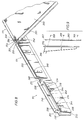
- a lock pin 220 has a shaft 222, an eyelet 224, and a hinged tail 226.
- the hinged tail 226 is coupled to the shaft 222 by a rivet 228.
- the lock pin 220 is used to couple various member together by positioning the hinged tail 226 in a linear arrangement with the shaft 222 and inserting the tail and shaft through a pin hole. The tail portion 226 is pulled through the hole until the hinged tail 226 can be rotated perpendicular to the shaft.
- the length of the shaft 222 between the eyelet 224 and the rivet 228 should be sufficient to pass through the coupled members and rubber washers there between, but not so long as to allow slack between the members.
- the eyelet 224 is useful for securing shock cords attached to custom cut fabric panels or anchoring guys.
- an elongate panel 92 made of a fabric or polymer sheet is provided with interlocking edges 94 and 96 that are slidably held within the guide channels 44/48 and 32/36, respectively.
- the guide channels may take any shape, but are preferably C-shaped with a constant diameter and an elongate opening that extends over the length of the guide channel. It is preferred that the opening or mouth of the channel be directed away from the support pole and positioned around the pole 90 degrees from the pin holes 24 and 26.
- FIG. 2A a cross section of the support member 12 taken along line 2 in FIG. 1 is shown with C-shaped guide channels 32 and 34 therein.
- the support member 12 is typically made of a lightweight metal, such as aluminum, and is preferably hollow to minimize the weight of the system while maintaining its strength.
- FIG. 2 also illustrates that the interlocking edge 96 of the panel 92 has a diameter less than the diameter of the channel 32 but greater than the width of the openings 98. Having these relative dimensions allows the interlocking edge 96 to be slidably held within the guide channel 32 while permitting the elongate flexible panel to extend through the opening 98.
- the panel 92 may be made of a variety of fabrics or plastic sheeting having sufficient strength to withstand wind loads and driving rain.
- the top edge 93 of the panel 92 is folded over and sewn for increased strength.
- a set of eyelets 95 are placed in the folded top edge 93 for securing custom panels (not shown).
- a panel tensioner 82 is attached to the cross brace 58 in order to put tension on the panel and prevent it from flapping in the wind.
- the tensioner 82 is a strong flexible material, typically a steel rod.
- One end of the tensioner 82, such as end 84, is inserted into a hole 86 in the cross brace 58.
- the tensioner 82 is then bowed outwards toward the panel until the proper tension is achieved. Then the other end 88 of the tensioner 82 is inserted into a hole 90.
- the system also includes means for controllably raising and lowering the flexible panel.
- the panels may be raised and lowered by hand or any other means.
- the system may include a pair of cables 100 and 102 connected to the top interlocking edges 94 and 96 of the panel 92.
- the cables 100 and 102 pass upward from the panel 92 through the channel 32 to a halyard winch 104.
- the winch 104 may have arms 114 and 116 which are secured to the distal ends 106 and 108 of the adjacent support poles 16 and 40, respectively.
- the winch 170 be detachably secured to an angle iron cross brace 172 so that a single winch and a pair of cables can be used to raise all the fabric panels consecutively.
- the winch 170 includes a frame 174 that can be attached to the cross brace 172 by setting the mounting channel 176 of the frame 174 over the back of the brace 172 and rotating the locking bar 178 into a position under the brace 172.
- the winch 170 is free to slide along the brace 172 as necessary to equalize the tension on the pair of cables 180 and 182.
- the winch 170 further includes a drum 184 with dual tracks 186 and 188 for receiving the cables 180 and 182, respectively.
- a shaft 190 is placed through the center of the drum 184 and extending through both sides of the frame 174.
- One end of the shaft 190 is connected to a crank 192 for turning the drum 184.
- pulleys 194 are temporarily mounted on the distal ends of the support poles 198. These pulleys 194 have a male extension 202 which fits snugly into the C-channel 200 of each support pole 198. The pulleys 194 allow the cables 180 and 182 to be pulled in a direction linear to the C-channels 200, thereby reducing the force required to raise the fabric.
- the winch 104 allows the cables 100 and 102 to communicate with a spool or drum 110 to which they are attached.
- the drum 110 has a hand crank 112 or other hand-operated or electronic means for turning the drum.
- the cables are attached to the drum so that rotation of the drum causes tension on the cables. Further rotation causes the cables to be wound onto the drum and the attached panel to be raised.
- the drum can be rotated in the opposite direction to lower the panel.
- the components of the system just described can be configured in a variety of ways.
- the system can be made taller by linking additional support members to the vertical support poles.
- the system can be made wider by installing a plurality of vertical support poles and panels across the desired area.
- the poles may be positioned in a straight line, a curve, or an angle as needed for protection of the construction area.
- the present invention may be used economically in applications that are much wider than tall, such as covering the walls of a single story building.
- the system 210 can be mounted with the support poles 212 and 214 in a horizontal arrangement.
- Stanchion adapters 216 can be used to connect the poles at standard lock pin positions. In this configuration, fewer fabric panels and less labor are required.
- the system 120 includes nine support poles 122 spaced a uniform distance apart to accommodate up to eight elongate panels.
- the poles 122 are comprised of a combination of straight and curved support members to form inverted frame sweep bends.
- the frame sweep bends shown provide enclosed protection over a space sufficient for a three tier scaffold system 126 to be constructed for the laying of a brick or concrete block wall.
- the curved or bent support members 123 and 125 can have any degree of deflection so long as the panel's interlocking edge does not bind in the channel. However, members 123 and 125 will typically have a 60 degree deflection in order to establish a 30 degree roof slope. When the system is configured horizontally, the sweep bends may be 90 degrees to provide for corner turns.
- a winch 128 is placed at the distal end of the poles, which is now located at ground level.
- the cables pass upward and over the top portion of the poles and attach to a panel which is typically rolled or folded near the front base of the system.
- a panel which is typically rolled or folded near the front base of the system.
- only three panels 124 are shown to be fully extended into the enclosed position.
- the panel 130 is shown only partially closed with a portion of the panel 130 remaining in a roll at point 132.
- weight of panel material is substantially the same on both sides of the system. Therefore, retracting the panel may require a downward pull on the front portion of the panel in addition to releasing cable from the winch.
- weights 134 may be hung on the front portion of the panel so that there is always tension on the panel and cables and a single person can open the protective covering.
- cross braces 136 are necessary for the system to have sufficient rigidity to stand upright and resist winds and rain. In certain circumstances such as this, it might be beneficial to secure the system 120 in place with a cable 138 and stake 140. Furthermore, rubber washers may be placed between each of the members connected, such as between the support member 14, the cross brace 58, and the frame brace 70, in order to provide additional stability to the system.
- FIG. 4 another configuration of the system of the present invention 140 is shown covering a scaffold 142 against an existing wall 144.
- the support poles 146 are attached to the scaffold at various points 148 and extend up and over the scaffold to make contact with the cave 150 of the roof 152.
- Panel 154 is shown being partially raised by the winch 156.
- custom panels 164, 166, and 168 are secured into place with standard S-hooked shock cords extending from the custom panels to eye bolts or toggle lock pins with eyelets (see FIG. 7) located at the various connections between support poles and cross braces. It is also possible to fasten the shock cords to the eyelets located along the top edge of the panels.
- a wall soffit and facia attachment 171 may be secured to the wall 144 or cave 150 for holding the support poles and fabric thereto in a continuous, weather tight manner.
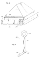
- the attachment 171 is shown in greater detail.
- the attachment includes a base plate track 230, a sliding lock track 232, and multiple cam lock levers 234. These three components are fastened together, for example by a rivet 236, in slidable contact.
- the attachment 171 is secured to a wall by use of fasteners, such as installing a screw 238 through the base plate 230 into the wall.
- the base plate track 230 has a semicircular portion 240 which opens downward and the sliding lock track 232 has a semicircular portion 242 which opens upward.
- the cam lock levers 234 When the cam lock levers 234 are turned in the direction of arrows 244, the levers 234 engage the underneath side of the sliding lock track 232 forcing the semicircular portion 242 of the sliding lock track 232 upwards toward the semicircular portion 240 of the base plate track 230.
- the cam lock levers are fully closed (shown at points 246), the two semicircular portions 240 and 242 form a C-channel 248 having a small opening 250 along the front edge.
- a series of attachments 171 is installed side-by-side in edgewise contact.
- the channel 248 extends substantially the width of the attachment 171, but leaves a gap 251 at each end of the attachment 171 sufficient for an arm 253 of a C-track-to-frame locking pin 252, which is coupled to the support pole 255, to pass between the adjacent channels 248.
- the arm 253 has a lock lug 254 that is captured by the channels 248 when the sliding lock track 232 is secured in the upward position.
- the C-track 248 captures the interlocking top edge 256 of the fabric panel 258. Therefore, both the support pole 255 and the fabric panel 258 are secured in place to protect the underlying structure from the weather.
- An alternate embodiment of the present invention uses a modified support member 260, as shown in FIG. 2B, formed by coupling two identical support pieces 261, 263.
- the half-tracks 262 of support piece 261 cooperate with the half-tracks 264 of support piece 263 to create two C-tracks 265 connected by a flat metal bar 267.
- each flat support member 260 have multiple holes or slots 266 through the center of the flat metal bar 267 which allow the support member 260 to be coupled to mating holes in a rigid structure. While the support member of FIG.
- the support member 260 may be fastened to the rigid structure by any means known in the art, including clamps, ties, rivots, tack welding, and the like.
- the flat support member 260 of FIG. 2B is used substantially in the same manner as the support member 12 in FIG. 2A, except that the flat metal bar 267 can be coupled directly to a rigid structure, such as a scaffold 270, eliminating the need for frame braces, cross braces, and bases.
- the support member 260 is attached to the rigid structure 270 with bolts 268, or other fastening means. It is preferred that the support members 260 have substantially the same length as a typical scaffold unit 270 for the sake of convenience. In fact, when a certain configuration is to be used repeatedly, it is possible to leave the support member 260 attached to the scaffold members when disassembled. It is also anticipated that the flat support members 260 or guide channels could be permanently affixed to the scaffold or other structure or originally manufactured as a part of the scaffold unit.
- FIG. 10 the ends of two support members 260 with dual C-tracks 265 are shown being coupled by a splice bar 274 which has holes 276 matching up with slots 266 in the members 260. It is desirable to couple or splice the support members 260 in situations or configurations where the members 260 must span between distant structural members or for any other reason that requires the splice bar 274 to keep the C-tracks 265 aligned.
- FIG. 11A a pair of support members 260 with C-tracks are shown coupled together by a spacer 280 and eyebolt 282 with wingnut 284 .
- the arrangement of multiple support members 260 allows the use of panels in multiple layers 286 and 288,
- One useful configuration combines an isolation barrier in layer 286, such as to capture sand or shed rain, with a fall restraint in layer 288, such as a safety webbing.
- the particular embodiment illustrated in FIG. 11A is suspended by a strong cable 290 attached to the eyelet 282. In this arrangement the invention lends itself to use below bridges or other elevated structures where fall restraints are necessary.
- FIG. 11B shows two support members 260 coupled by a spacer 280 directly to a rigid structure 300, such as a scaffold, a metal I-beam, a concrete beam, or the like.
- the flat support members 260 can be configured to produce many different covering system, including horizontal and vertical walls, ceilings, and underlying barriers. Furthermore, the flat support members 260 may still be used in combination with the wall soffit and facia attachment 171.
Landscapes
- Engineering & Computer Science (AREA)
- Architecture (AREA)
- Mechanical Engineering (AREA)
- Civil Engineering (AREA)
- Structural Engineering (AREA)
- Tents Or Canopies (AREA)
- Laying Of Electric Cables Or Lines Outside (AREA)
- Cable Accessories (AREA)
- Building Awnings And Sunshades (AREA)
Description
Claims (12)
- A temporary protective covering system comprising: a pair of spaced support poles(16) each comprising an elongate support member having a first end, a second distal end, and means(68,70) for temporarily securing the support poles in a space relating to a structure; a plurality of cross braces(58) bracing and spacing said pair of support poles (16); facing guide channels(32,44) in said elongate support poles (16); and a flexible panel(92) between said support poles (16) having a width spanning between said support poles, two interlocking lateral edges(96) of the panel being slidably held within said guide channels(32,44), characterised in that means are provided for controllably moving said panel between said facing guide channels which means comprise elongate cables(100) extending at least partly along each of said guide channels(32,44), each cable(100) having one end coupled to said panel(92) and a remote end thereof for pulling.
- The system of Claim 1 wherein the guide channels(32,44) have a C-shaped cross-section of constant diameter and an elongate opening(98) with a constant width over the length of the guide channel, and wherein the diameter of the guide channel is greater than the diameter of the interlocking lateral edge(96) of the flexible panel(92), and wherein the width of the elongate opening is less than the diameter of the interlocking lateral edge of the flexible panel and greater than the thickness of the flexible panel.
- The system of Claim 1 or 2 further comprising means(82) for tensioning the flexible panels.
- The system of Claim 1, 2 or 3 further comprising a broad base member(50,52) coupled to the first end of the respective support pole(16) to distribute the weight of the support over a large area of the substantially horizontal surface.
- The system of any one of the preceding Claims further comprising: an adapter having a first end coupled to the distal end of a support pole(16) and a second end having a horizontal shaft(355); and a facia plate attached to a structure having a C-channel that can be opened for insertion of the horizontal adapter shaft and the top interlocking edge of the fabric panel, wherein the C-shape of the facia can be closed to securely hold the horizontal adapter shaft and the top interlocking edge of the fabric panel.
- The system of any one of the preceding Claims wherein the support poles are substantially vertical and the first end rests on a substantially horizontal surface.
- The system of any one of Claims 1 to 5 wherein said panel and said pair of spaced support poles are horizontal.
- The apparatus of Claim 7 wherein said spaced support poles are parallel, extend along a first side of the structure, and define a curving corner to thereby extend along a second side of the structure.
- A method for installing a temporary protective covering system comprising the steps of: (a) positioning first and second support poles(16) of substantially equal length in parallel alignment, each pole having a first end, a second distal end, and a guide channel(32,44); (b) installing a plurality of elongate cross braces(58) between the first and second support poles; (c) temporarily securing a winch(170) to a cross brace(172) near the distal ends of the first and second support poles; (d) temporarily attaching first and second pulleys(194,196) to the distal end of the first and second support poles; (e) threading first and second cables(180,182) from the winch, over the first and second pulleys, and downward through the guide channels of the first and second support poles; (f) coupling the first and second cables to a flexible panel(92) having interlocking edges(96); (g) cranking the winch(170) to reel in the cable and thereby extend the flexible panel; (h) during raising, slideably securing the interlocking edges within the guide channels; (i) attaching a facia plate(171) to a structure; (j) removing the pulleys(194,196) and the winch (170); (k) securing the distal ends of the first and second support poles(16) to the facia plate; (l) and securing the fabric panel to the facia plate.
- The method of Claim 9 further comprising the steps of: (m) securing the flexible panel to the distal ends of the support poles; and (n) removing the pulleys and the winch.
- The method of Claim 9 further comprising the steps of: (m) repeating steps (a)-(I) for a second panel.
- The method Claim 10 further comprising the steps of: (o) repeating steps of (a)-(n) for a second panel.
Applications Claiming Priority (3)
| Application Number | Priority Date | Filing Date | Title |
|---|---|---|---|
| US346690 | 1994-11-30 | ||
| US08/346,690 US5613543A (en) | 1994-11-30 | 1994-11-30 | Temporary protective covering system |
| PCT/US1995/004827 WO1996017146A1 (en) | 1994-11-30 | 1995-04-18 | Temporary protective covering system |
Publications (2)
| Publication Number | Publication Date |
|---|---|
| EP0795068A1 EP0795068A1 (en) | 1997-09-17 |
| EP0795068B1 true EP0795068B1 (en) | 1998-09-09 |
Family
ID=23360605
Family Applications (1)
| Application Number | Title | Priority Date | Filing Date |
|---|---|---|---|
| EP95917070A Expired - Lifetime EP0795068B1 (en) | 1994-11-30 | 1995-04-18 | Temporary protective covering system |
Country Status (7)
| Country | Link |
|---|---|
| US (1) | US5613543A (en) |
| EP (1) | EP0795068B1 (en) |
| JP (1) | JPH10510018A (en) |
| CN (1) | CN1171832A (en) |
| CA (1) | CA2182385C (en) |
| DE (1) | DE69504703T2 (en) |
| WO (1) | WO1996017146A1 (en) |
Cited By (1)
| Publication number | Priority date | Publication date | Assignee | Title |
|---|---|---|---|---|
| WO2024227914A1 (en) * | 2023-05-03 | 2024-11-07 | Huma Technologies Aps | A barrier system |
Families Citing this family (68)
| Publication number | Priority date | Publication date | Assignee | Title |
|---|---|---|---|---|
| SE507910C2 (en) * | 1996-06-19 | 1998-07-27 | Jonsereds Miljoesystem Ab | Structure coverage system |
| NL1011041C2 (en) * | 1998-11-10 | 2000-05-11 | Haan Serrebouw B V De | Shielding system for shielding work on a facade and associated herring. |
| NL1013541C2 (en) * | 1999-11-10 | 2001-05-11 | Haan Serrebouw B V De | Screen for concealing activities on buildings and civil engineering works comprises strips of flexible material held together by at least one curtain part and at least two coupling components |
| GB0005651D0 (en) * | 2000-03-10 | 2000-05-03 | Larin Normand | Collapsible balcony awning |
| ATE373757T1 (en) * | 2000-07-26 | 2007-10-15 | Patea Gmbh | SIDE COVERING ON A COLLAPSIBLE TENT |
| USD506331S1 (en) * | 2002-03-28 | 2005-06-21 | Alain Quintal | Workstation |
| US7377490B1 (en) * | 2004-09-27 | 2008-05-27 | Bahman Khosravian | Modular fence assembly |
| US20060175131A1 (en) * | 2005-02-09 | 2006-08-10 | Smith Jeffrey M | Protective weather-frame canopy enclosure for scaffolding |
| US7264012B2 (en) * | 2005-02-22 | 2007-09-04 | Slade Eric J | Supported roof tarp apparatus |
| US20060225960A1 (en) * | 2005-04-12 | 2006-10-12 | Ferlin Keith A | Enclosed scaffolding assembly |
| US20060249091A1 (en) * | 2005-05-06 | 2006-11-09 | Orbach David M | Portable screening device |
| US7987863B2 (en) * | 2005-09-21 | 2011-08-02 | Tentnology Limited | Modular pole tent and joining means |
| US8091605B1 (en) | 2006-01-25 | 2012-01-10 | Jim Melhart Piano and Organ Company | Acoustic panel assembly |
| US20070204559A1 (en) * | 2006-03-03 | 2007-09-06 | Claywell James D | Wind Blocking Device for Buildings |
| US20100024340A1 (en) * | 2006-03-03 | 2010-02-04 | Block Shields Llc | Wind blocking device for buildings |
| US20070283992A1 (en) * | 2006-06-10 | 2007-12-13 | Timothy Joseph Hennessy | Embrace-Air "TM" situates air conditioner and method for use with tent |
| US7950406B2 (en) * | 2006-07-10 | 2011-05-31 | First Principles, Inc. | Athletic course covering system |
| US7789927B2 (en) * | 2007-07-06 | 2010-09-07 | Kimberly-Clark Worldwide, Inc. | Portable breathable dust partition system |
| US8359965B2 (en) | 2007-09-17 | 2013-01-29 | Oxford J Craig | Apparatus and method for broad spectrum radiation attenuation |
| CN101952535A (en) * | 2007-10-15 | 2011-01-19 | 飓风布网站有限责任公司 | Weather protection system |
| US20090308548A1 (en) * | 2008-06-16 | 2009-12-17 | Tramontina Paul F | Temporary partition curtain |
| US7913711B2 (en) * | 2008-07-28 | 2011-03-29 | Shelterlogic Llc | Door assembly for use in a shelter and a shelter including same |
| DE202008015851U1 (en) | 2008-11-29 | 2010-04-15 | Baumgärtner, Martin, Dipl.-Ing. (FH) | Component for cladding or construction of buildings |
| DE102008059715A1 (en) | 2008-11-29 | 2010-06-10 | Baumgärtner, Martin, Dipl.-Ing. (FH) | Component for cladding or construction of buildings |
| US7931037B1 (en) * | 2009-02-25 | 2011-04-26 | Ryan Jason S | Covering system |
| US20100243977A1 (en) * | 2009-03-27 | 2010-09-30 | Middlebrook Jr Alanson J | Apparatus for Protecting Mailboxes from Snowplow Damage |
| US8701689B2 (en) * | 2010-02-12 | 2014-04-22 | 0798555 B.C. Ltd. | Saddle shaped tent with portico |
| US20120273139A1 (en) * | 2011-04-27 | 2012-11-01 | Morales Ruben N | Apparatus, system, and method for covering a window |
| US20120273140A1 (en) * | 2011-04-27 | 2012-11-01 | Morales Ruben N | Apparatus, system, and method for covering a window |
| US8973645B1 (en) * | 2011-08-24 | 2015-03-10 | Carl S. Cannova | Portable wind-resistant traffic screen and related method |
| AU2012318264B2 (en) * | 2011-10-31 | 2016-07-14 | Synergy Scaffolding Holdings Pty Ltd | An electrically insulated screen and method of erecting an electrically insulated screen |
| CA2794484C (en) | 2011-11-03 | 2020-09-22 | Awol Outdoors, Inc. | Fold-out trailer with retractable wheel assembly |
| US9332860B2 (en) | 2012-02-08 | 2016-05-10 | Kids Ii, Inc. | Play yard with removable liner |
| CN102677910A (en) * | 2012-05-25 | 2012-09-19 | 长沙圣华科技发展有限公司 | Wind-preventing method for water-saving moisture-preserving concrete maintaining film in strong wind environment |
| JP5623467B2 (en) * | 2012-07-02 | 2014-11-12 | 中国電力株式会社 | Curing sheet installation equipment |
| US9301624B2 (en) | 2012-08-07 | 2016-04-05 | Thorley Industries Llc | Foldable play yard apparatus including a clamp and a method of attaching a flexible sheet to the clamp |
| US9763523B2 (en) | 2012-09-10 | 2017-09-19 | Kids Ii, Inc. | Bassinet support |
| US9801473B2 (en) | 2012-09-13 | 2017-10-31 | Kids Ii, Inc. | Play yard with removable liner |
| DE102013206584A1 (en) * | 2013-04-12 | 2014-10-16 | Peri Gmbh | PLAN ROLE |
| WO2014195807A2 (en) * | 2013-05-24 | 2014-12-11 | L'air Liquide, Societe Anonyme Pour L'etude Et L'exploitation Des Procedes Georges Claude | Manufacturing yard |
| US9194142B2 (en) * | 2013-06-04 | 2015-11-24 | Glenmore Industries LLC | Modular wall system for exhibition booths |
| US10702085B1 (en) | 2013-12-19 | 2020-07-07 | Deck Dressings, Llc. | Deck curtain system and method of use |
| US9567800B1 (en) * | 2013-12-19 | 2017-02-14 | Deck Dressings, LLC | Deck curtain system and method of use |
| US9283413B2 (en) * | 2014-04-03 | 2016-03-15 | Polo Custom Products | Fire curtain assembly and method of use |
| US9422732B2 (en) * | 2014-04-28 | 2016-08-23 | Ted Gower | Slidable barriers |
| US10952544B2 (en) | 2015-03-30 | 2021-03-23 | Kids2, Inc. | Child support device |
| US10477981B2 (en) | 2015-04-25 | 2019-11-19 | Kids2, Inc. | Depth-adjustable fabric enclosure |
| CN105350755A (en) * | 2015-11-26 | 2016-02-24 | 重庆钢星建筑工程有限公司 | Novel scaffold |
| CN105350756A (en) * | 2015-11-26 | 2016-02-24 | 重庆钢星建筑工程有限公司 | Scaffold |
| JP6150872B2 (en) * | 2015-11-30 | 2017-06-21 | 仁村 優治 | Seat mounting device for temporary buildings |
| JP6999943B2 (en) | 2016-03-20 | 2022-01-19 | アウォル アウトドアーズ,インコーポレイテッド | Foldable and portable partial or total storage device |
| DE202016106196U1 (en) * | 2016-11-04 | 2018-02-06 | Teupe Gmbh | Protective device for persons working on a building |
| EP3635201A4 (en) | 2017-05-08 | 2021-01-27 | McGregor, Shawn | FOLDING CLOSURE |
| US10145121B1 (en) * | 2017-06-01 | 2018-12-04 | Midwest Industries, Inc. | Canopy |
| GB2577668A (en) * | 2018-05-14 | 2020-04-08 | Specialist Safety Netting Ltd | An extendable scaffolding safety barrier and method |
| US20200079577A1 (en) * | 2018-09-07 | 2020-03-12 | Jeanne Ngo | Urine-absorbing sheets and dispensing devices |
| US11466467B2 (en) | 2019-01-31 | 2022-10-11 | Nicholas L. Kowalski | Modular construction shelter |
| US11134795B2 (en) * | 2019-10-10 | 2021-10-05 | DuckUp LLC | Infant safety barrier |
| US10947776B1 (en) | 2019-11-04 | 2021-03-16 | Gnb Global Inc. | Tensioned sheet wall system for a building |
| AT523418B1 (en) * | 2020-03-05 | 2021-08-15 | ||
| US12590463B2 (en) * | 2020-10-14 | 2026-03-31 | Frank Spadola | Privacy shade |
| CN112081366B (en) * | 2020-10-21 | 2021-11-23 | 肥城联谊工程塑料有限公司 | Winding and laying type building climbing frame net |
| CN112227756A (en) * | 2020-11-12 | 2021-01-15 | 中建四局第三建设有限公司 | Protective structure in steel structure building roof board renewing engineering |
| CH718271A1 (en) * | 2021-01-19 | 2022-07-29 | Ghelma Ag Spezialtiefbau | Method of creating a protective scaffold |
| EP4036349A1 (en) | 2021-01-27 | 2022-08-03 | GNB Global Inc. | Tensioned sheet wall system for a building |
| CN114837396A (en) * | 2022-05-12 | 2022-08-02 | 中国建筑第二工程局有限公司 | Telescopic operation platform for light production well and construction method thereof |
| CN221838221U (en) * | 2023-12-29 | 2024-10-15 | 宋勇 | Connecting rod piece |
| WO2025171446A1 (en) * | 2024-02-15 | 2025-08-21 | Scaffcover Holdings IP Pty Ltd | Modular scaffolding cladding system |
Family Cites Families (32)
| Publication number | Priority date | Publication date | Assignee | Title |
|---|---|---|---|---|
| US158455A (en) * | 1875-01-05 | Improvement in fire-shields | ||
| US193573A (en) * | 1877-06-01 | 1877-07-24 | Improvement in movable partitions or screens | |
| US1546848A (en) * | 1924-09-15 | 1925-07-21 | Ralph A Lundgren | Casement-window screen with operating mechanism |
| GB518040A (en) * | 1938-09-14 | 1940-02-15 | William Lancelot Robertshaw | Improvements in and relating to window and like blinds |
| US2466155A (en) * | 1946-03-30 | 1949-04-05 | Airquipment Company | Adjustable workstand |
| US2986150A (en) * | 1958-03-17 | 1961-05-30 | Torian William Harold | Means for mounting thin, flexible membranes |
| US3155427A (en) * | 1963-03-22 | 1964-11-03 | Joseph P Necessary | Stadium seat |
| US3240217A (en) * | 1963-11-08 | 1966-03-15 | Birdair Structures | Structural assembly |
| US3510996A (en) * | 1966-03-17 | 1970-05-12 | Nicholas B Popil | Retractable covering |
| US3586126A (en) * | 1969-03-11 | 1971-06-22 | John K Eickhof | Portable enclosure and method of erecting same |
| US3749107A (en) * | 1971-05-18 | 1973-07-31 | N Laberge | Collapsible garage |
| US3805816A (en) * | 1971-12-10 | 1974-04-23 | R Nolte | Protective covering |
| DE2217826A1 (en) * | 1972-04-13 | 1973-10-25 | Kusto Gmbh | Construction shrouding - with rolled material supported by uprights |
| US4083149A (en) * | 1976-05-21 | 1978-04-11 | Capital Steel & Supply Co., Division Of Jensen Investment Corporation | Drop vent wall system |
| US4124196A (en) * | 1977-03-10 | 1978-11-07 | Hipskind Myron M | Portable device for screening off an accident scene from view |
| DE2815848A1 (en) * | 1977-10-07 | 1978-10-26 | Shelter Span Building Syst | Dismountable building structure |
| DE3014724C2 (en) * | 1980-04-17 | 1982-08-12 | Festzeltbetriebe Sony-Boy Papert, 8050 Freising | Pulling and pulling device for tarpaulin for large tents |
| SE8406187L (en) * | 1984-12-06 | 1986-06-07 | Lennart Svensson | TREATMENT DEVICE |
| DE3539362A1 (en) * | 1985-09-16 | 1987-05-14 | Rainer Steffens | Means for the rain-tight covering of a facade or the like to be renovated |
| US4744403A (en) * | 1986-10-17 | 1988-05-17 | Appropriate Technology Corporation | Retrofittable insulating system for solar rooms |
| DE3716552A1 (en) * | 1987-05-18 | 1988-12-08 | Juergen Eyerich | Metal trussed girder |
| US4738335A (en) * | 1987-07-06 | 1988-04-19 | Nihon Biso Kabushiki Kaisha | Scaffolding system for performing a work on an outer wall surface of a building |
| JP2587684B2 (en) * | 1988-07-19 | 1997-03-05 | 日本ビソー株式会社 | Construction wall construction equipment |
| US4852687A (en) * | 1989-02-24 | 1989-08-01 | Grayling Industries, Inc. | Method and apparatus for hazardous material containment and disposal |
| US5038517A (en) * | 1989-05-19 | 1991-08-13 | Talbott Gene B | Greenhouse construction |
| US4982534A (en) * | 1989-05-19 | 1991-01-08 | Mitsui Construction Co., Ltd. | Suspended membrane structure |
| US4984399A (en) * | 1990-06-25 | 1991-01-15 | Taylor Gary L | Automobile enclosure |
| US5038889A (en) * | 1990-10-29 | 1991-08-13 | Jankowski Steven R | Scaffold enclosure |
| US5197240A (en) * | 1991-09-24 | 1993-03-30 | Eryou N Dennis | Transfer pad cover |
| US5201152A (en) * | 1992-07-31 | 1993-04-13 | The Babcock & Wilcox Company | Containment device for contaminated building demolition |
| NO177802C (en) * | 1993-03-29 | 1995-11-22 | Malthus Bygg & Maskin As | Device for scaffolding |
| DE9305738U1 (en) * | 1993-04-16 | 1993-06-17 | MJ-Gerüst GmbH, 5970 Plettenberg | Device for securing tarpaulins to scaffolding |
-
1994
- 1994-11-30 US US08/346,690 patent/US5613543A/en not_active Expired - Lifetime
-
1995
- 1995-04-18 EP EP95917070A patent/EP0795068B1/en not_active Expired - Lifetime
- 1995-04-18 CN CN95197233A patent/CN1171832A/en active Pending
- 1995-04-18 DE DE69504703T patent/DE69504703T2/en not_active Expired - Fee Related
- 1995-04-18 WO PCT/US1995/004827 patent/WO1996017146A1/en not_active Ceased
- 1995-04-18 JP JP8518724A patent/JPH10510018A/en active Pending
- 1995-04-18 CA CA002182385A patent/CA2182385C/en not_active Expired - Fee Related
Cited By (1)
| Publication number | Priority date | Publication date | Assignee | Title |
|---|---|---|---|---|
| WO2024227914A1 (en) * | 2023-05-03 | 2024-11-07 | Huma Technologies Aps | A barrier system |
Also Published As
| Publication number | Publication date |
|---|---|
| WO1996017146A1 (en) | 1996-06-06 |
| JPH10510018A (en) | 1998-09-29 |
| CN1171832A (en) | 1998-01-28 |
| DE69504703T2 (en) | 1999-02-04 |
| AU2390195A (en) | 1996-06-19 |
| US5613543A (en) | 1997-03-25 |
| EP0795068A1 (en) | 1997-09-17 |
| CA2182385C (en) | 2000-08-08 |
| DE69504703D1 (en) | 1998-10-15 |
| CA2182385A1 (en) | 1996-06-06 |
| AU693196B2 (en) | 1998-06-25 |
Similar Documents
| Publication | Publication Date | Title |
|---|---|---|
| CA2182385C (en) | Temporary protective covering system | |
| CA2051591C (en) | Scaffold enclosure | |
| US5966877A (en) | Rapidly deployable protective and structural cover system | |
| US6412540B2 (en) | Structural protective windscreen | |
| US4404980A (en) | Arched support structure with cover | |
| US4593710A (en) | Framed tension structure | |
| US4191361A (en) | Lockbar for fence post mounting | |
| EP3362611B1 (en) | Door system for movable structures | |
| WO1986003538A1 (en) | A weather protecting device for stands | |
| US10858856B1 (en) | Modular tent construction and components thereof | |
| US6421980B1 (en) | Method of dispensing netting for a roof structure | |
| US20120180838A1 (en) | Method of erecting portable structure and related apparatus | |
| AU693196C (en) | Temporary protective covering system | |
| US20050139423A1 (en) | Enclosure system for scaffolding | |
| JP4108854B2 (en) | Temporary roof | |
| JP2764366B2 (en) | Temporary tent with opening and closing mechanism | |
| JP2623072B2 (en) | Dome type temporary tent and its assembling method | |
| US20060157300A1 (en) | Enclosure system for scaffolding | |
| US20060175131A1 (en) | Protective weather-frame canopy enclosure for scaffolding | |
| WO2011061407A1 (en) | An apparatus for covering a wall | |
| JP2620681B2 (en) | Temporary roof | |
| EP4394143A1 (en) | Scaffolding assembly | |
| JP3694666B2 (en) | Temporary tent | |
| JP7508068B2 (en) | Outdoor installation equipment work tent device | |
| KR102723067B1 (en) | The A method and device for controlling membrane tension in the form of a warming and cooling tent or shading membrane to maintain the working temperature of the inner space of gang foam for apartments |
Legal Events
| Date | Code | Title | Description |
|---|---|---|---|
| PUAI | Public reference made under article 153(3) epc to a published international application that has entered the european phase |
Free format text: ORIGINAL CODE: 0009012 |
|
| 17P | Request for examination filed |
Effective date: 19970606 |
|
| AK | Designated contracting states |
Kind code of ref document: A1 Designated state(s): BE CH DE DK ES FR GB IT LI NL SE |
|
| GRAG | Despatch of communication of intention to grant |
Free format text: ORIGINAL CODE: EPIDOS AGRA |
|
| 17Q | First examination report despatched |
Effective date: 19971021 |
|
| GRAG | Despatch of communication of intention to grant |
Free format text: ORIGINAL CODE: EPIDOS AGRA |
|
| GRAH | Despatch of communication of intention to grant a patent |
Free format text: ORIGINAL CODE: EPIDOS IGRA |
|
| GRAH | Despatch of communication of intention to grant a patent |
Free format text: ORIGINAL CODE: EPIDOS IGRA |
|
| GRAA | (expected) grant |
Free format text: ORIGINAL CODE: 0009210 |
|
| AK | Designated contracting states |
Kind code of ref document: B1 Designated state(s): BE CH DE DK ES FR GB IT LI NL SE |
|
| PG25 | Lapsed in a contracting state [announced via postgrant information from national office to epo] |
Ref country code: NL Free format text: LAPSE BECAUSE OF FAILURE TO SUBMIT A TRANSLATION OF THE DESCRIPTION OR TO PAY THE FEE WITHIN THE PRESCRIBED TIME-LIMIT Effective date: 19980909 Ref country code: LI Free format text: LAPSE BECAUSE OF FAILURE TO SUBMIT A TRANSLATION OF THE DESCRIPTION OR TO PAY THE FEE WITHIN THE PRESCRIBED TIME-LIMIT Effective date: 19980909 Ref country code: IT Free format text: LAPSE BECAUSE OF FAILURE TO SUBMIT A TRANSLATION OF THE DESCRIPTION OR TO PAY THE FEE WITHIN THE PRE;WARNING: LAPSES OF ITALIAN PATENTS WITH EFFECTIVE DATE BEFORE 2007 MAY HAVE OCCURRED AT ANY TIME BEFORE 2007. THE CORRECT EFFECTIVE DATE MAY BE DIFFERENT FROM THE ONE RECORDED.SCRIBED TIME-LIMIT Effective date: 19980909 Ref country code: ES Free format text: THE PATENT HAS BEEN ANNULLED BY A DECISION OF A NATIONAL AUTHORITY Effective date: 19980909 Ref country code: CH Free format text: LAPSE BECAUSE OF FAILURE TO SUBMIT A TRANSLATION OF THE DESCRIPTION OR TO PAY THE FEE WITHIN THE PRESCRIBED TIME-LIMIT Effective date: 19980909 Ref country code: BE Free format text: LAPSE BECAUSE OF FAILURE TO SUBMIT A TRANSLATION OF THE DESCRIPTION OR TO PAY THE FEE WITHIN THE PRESCRIBED TIME-LIMIT Effective date: 19980909 |
|
| REG | Reference to a national code |
Ref country code: CH Ref legal event code: EP |
|
| REF | Corresponds to: |
Ref document number: 69504703 Country of ref document: DE Date of ref document: 19981015 |
|
| PG25 | Lapsed in a contracting state [announced via postgrant information from national office to epo] |
Ref country code: SE Free format text: LAPSE BECAUSE OF FAILURE TO SUBMIT A TRANSLATION OF THE DESCRIPTION OR TO PAY THE FEE WITHIN THE PRESCRIBED TIME-LIMIT Effective date: 19981209 Ref country code: DK Free format text: LAPSE BECAUSE OF FAILURE TO SUBMIT A TRANSLATION OF THE DESCRIPTION OR TO PAY THE FEE WITHIN THE PRESCRIBED TIME-LIMIT Effective date: 19981209 |
|
| NLV1 | Nl: lapsed or annulled due to failure to fulfill the requirements of art. 29p and 29m of the patents act | ||
| ET | Fr: translation filed | ||
| REG | Reference to a national code |
Ref country code: CH Ref legal event code: PL |
|
| PLBE | No opposition filed within time limit |
Free format text: ORIGINAL CODE: 0009261 |
|
| STAA | Information on the status of an ep patent application or granted ep patent |
Free format text: STATUS: NO OPPOSITION FILED WITHIN TIME LIMIT |
|
| 26N | No opposition filed | ||
| PGFP | Annual fee paid to national office [announced via postgrant information from national office to epo] |
Ref country code: GB Payment date: 20000419 Year of fee payment: 6 |
|
| PGFP | Annual fee paid to national office [announced via postgrant information from national office to epo] |
Ref country code: FR Payment date: 20000426 Year of fee payment: 6 |
|
| PG25 | Lapsed in a contracting state [announced via postgrant information from national office to epo] |
Ref country code: GB Free format text: LAPSE BECAUSE OF NON-PAYMENT OF DUE FEES Effective date: 20010418 |
|
| PG25 | Lapsed in a contracting state [announced via postgrant information from national office to epo] |
Ref country code: FR Free format text: THE PATENT HAS BEEN ANNULLED BY A DECISION OF A NATIONAL AUTHORITY Effective date: 20010430 |
|
| PGFP | Annual fee paid to national office [announced via postgrant information from national office to epo] |
Ref country code: DE Payment date: 20010813 Year of fee payment: 7 |
|
| GBPC | Gb: european patent ceased through non-payment of renewal fee |
Effective date: 20010418 |
|
| REG | Reference to a national code |
Ref country code: FR Ref legal event code: ST |
|
| PG25 | Lapsed in a contracting state [announced via postgrant information from national office to epo] |
Ref country code: DE Free format text: LAPSE BECAUSE OF NON-PAYMENT OF DUE FEES Effective date: 20021101 |