EP0794743B1 - Element de brossage pour une brosse a dents electrique - Google Patents
Element de brossage pour une brosse a dents electrique Download PDFInfo
- Publication number
- EP0794743B1 EP0794743B1 EP95929885A EP95929885A EP0794743B1 EP 0794743 B1 EP0794743 B1 EP 0794743B1 EP 95929885 A EP95929885 A EP 95929885A EP 95929885 A EP95929885 A EP 95929885A EP 0794743 B1 EP0794743 B1 EP 0794743B1
- Authority
- EP
- European Patent Office
- Prior art keywords
- brush
- bristle carrier
- brush section
- axis
- shaft
- Prior art date
- Legal status (The legal status is an assumption and is not a legal conclusion. Google has not performed a legal analysis and makes no representation as to the accuracy of the status listed.)
- Expired - Lifetime
Links
Images


Classifications
-
- A—HUMAN NECESSITIES
- A61—MEDICAL OR VETERINARY SCIENCE; HYGIENE
- A61C—DENTISTRY; APPARATUS OR METHODS FOR ORAL OR DENTAL HYGIENE
- A61C17/00—Devices for cleaning, polishing, rinsing or drying teeth, teeth cavities or prostheses; Saliva removers; Dental appliances for receiving spittle
- A61C17/16—Power-driven cleaning or polishing devices
- A61C17/22—Power-driven cleaning or polishing devices with brushes, cushions, cups, or the like
- A61C17/32—Power-driven cleaning or polishing devices with brushes, cushions, cups, or the like reciprocating or oscillating
- A61C17/34—Power-driven cleaning or polishing devices with brushes, cushions, cups, or the like reciprocating or oscillating driven by electric motor
-
- A—HUMAN NECESSITIES
- A61—MEDICAL OR VETERINARY SCIENCE; HYGIENE
- A61C—DENTISTRY; APPARATUS OR METHODS FOR ORAL OR DENTAL HYGIENE
- A61C17/00—Devices for cleaning, polishing, rinsing or drying teeth, teeth cavities or prostheses; Saliva removers; Dental appliances for receiving spittle
- A61C17/16—Power-driven cleaning or polishing devices
- A61C17/22—Power-driven cleaning or polishing devices with brushes, cushions, cups, or the like
- A61C17/40—Power-driven cleaning or polishing devices with brushes, cushions, cups, or the like orbiting, e.g. nutating
-
- A—HUMAN NECESSITIES
- A61—MEDICAL OR VETERINARY SCIENCE; HYGIENE
- A61C—DENTISTRY; APPARATUS OR METHODS FOR ORAL OR DENTAL HYGIENE
- A61C17/00—Devices for cleaning, polishing, rinsing or drying teeth, teeth cavities or prostheses; Saliva removers; Dental appliances for receiving spittle
- A61C17/16—Power-driven cleaning or polishing devices
- A61C17/22—Power-driven cleaning or polishing devices with brushes, cushions, cups, or the like
- A61C17/24—Power-driven cleaning or polishing devices with brushes, cushions, cups, or the like rotating continuously
- A61C17/26—Power-driven cleaning or polishing devices with brushes, cushions, cups, or the like rotating continuously driven by electric motor
Definitions
- the invention relates generally to an electric toothbrush, and more particularly a brush part for an electric toothbrush according to the characteristics of Preamble of claim 1.
- Such a brush part is known from WO 94/12121, in particular Fig. 5.
- the axis of the brush part according to the prior art is by means of a Bearing ball stored in a spherical bearing. It follows that the axis around a pivot point is pivotable.
- There is also a rod for the drive the brush part is fixed within a bore of a shaft in the axial direction. This means that the bar can rotate on its own axis, but not in be moved in the axial direction. Will the wave alternate or rotating rotary movement, this has an alternating rotary movement of the bristle holder.
- Another part of the brush is from the German patent application DE 39 37 850 A1 known.
- an electric toothbrush that has a handle part from which a drive shaft protrudes.
- On the handle and the The drive shaft can be a brush part extending in the direction of the longitudinal axis be plugged on, which has a carrier tube, at the end of a bristle carrier is arranged.
- a shaft is housed, which in plugged state is coupled to the drive shaft. From the bristle holder protrude bristles, which are arranged approximately transversely to the longitudinal axis of the brush part are.
- the bristle holder is switched on State of the electric toothbrush an oscillating rotary movement around a about transverse to the longitudinal axis of the brush part arranged axis.
- the of the free ends of the bristles formed cleaning surface also leads oscillating rotary motion on the tooth surfaces of the user's teeth. With this oscillating rotary movement, the cleaning is already good Tooth surfaces accessible.
- the object of the invention is to provide a brush part for an electric toothbrush create with which improved tooth cleaning can be achieved.
- this object is at the beginning of a brush part mentioned type solved by the features of claim 1.
- the free ends of the bristles lead short Lifting or pushing movements in a direction more or less parallel to the Bristles or the brush axis.
- an essential better cleaning effect can be achieved in tooth cleaning. It is it is not necessary for the user to brush the toothed part to the tooth surfaces or in particular to the interdental areas.
- the movement of the bristle carrier according to the invention is determined by the acute angle between the transverse axis and the bristle axis reached.
- the brush axis and thus the bristle holder move on a cone shell of a cone, the central axis of which is from the transverse axis is formed.
- the nutation movement is thus simple generated, which requires only a small amount of components.
- a particularly advantageous embodiment of the invention according to the claim 2 is that the apex of the cone shell outside the Bristle field lies. This causes the lifting and thrusting movements of the free Cover the tooth surfaces to be cleaned from all sides of the ends of the bristles.
- the apex of the cone shell can also be within the bristle field, but are close to the tooth surface. It is particularly useful doing the angle between the transverse axis and the bristle axis from the im Select claim 5 specified range of values. In particular has there is an angle of about 6 to 3 degrees for an arrangement of the vertex within the tooth or an angle of approximately 10 to 5 degrees for an arrangement the vertex outside the tooth was found to be advantageous.
- the pinion is connected to a bearing pin which is rotatably supported in the carrier tube is.
- the crown gear with a Wedge disc connected in which another bearing pin is held.
- This serves according to claim 10 to rotatably support the bristle carrier.
- This configuration is a simple and inexpensive way to do that with few components To produce wobble according to the invention.
- a cranked shaft which can also be designed as a crankshaft can, provided.
- This is on the one hand in the carrier tube and on the other hand according to claim 10 rotatably mounted in the bristle carrier. Between can be arranged according to claim 9, a wedge be.
- the shaft is bent such that its two ends in the claim Take 2 acute angles to each other.
- the Described configuration is therefore particularly with regard to the manufacture the brush part very inexpensive.
- the self-rotation of the bristle carrier is by prevents a groove running in the direction of the longitudinal axis in the support tube into which a finger of the bristle holder engages. There are therefore no further components required, but the self-rotation is due to a special design the existing components prevented.
- a particularly simple embodiment of the retaining spring is in claim 14 specified.
- the retaining spring there caused only with regard to their manufacture low cost.
- the bristle carrier rotates itself associated bevel gear teeth on the carrier tube and on the bristle carrier generated.
- the rotational speed of this self-rotation, especially in With regard to the rotational speed of the wobble movement according to the invention can be done in a simple manner by the choice of the tooth ratio of the bevel gear to be influenced.
- the bristle holder can be due to its rotatable bearing rotary movements, in particular a rotation or Carry out oscillation, which are however uncontrolled and by the way depend on how the user places the bristles on the tooth surfaces.
- the invention is not only in the form of the brush part can be realized as such, but also in shape an electric toothbrush on which a corresponding brush part, for example is attached.
- the electric toothbrush according to the claim is particularly advantageous 22 has a continuously rotating drive. In this way a uniform wobbling movement of the bristle carrier is achieved. Basically, it is also possible that the electric toothbrush with a oscillating drive is provided.
- FIGS. 1 to 8 brush parts described below are suitable for operation with an electric toothbrush, as in the German Laid-open publication DE 39 37 850 A1.
- the one in the aforementioned publication explained oscillating drive of the electric toothbrush can however according to the invention preferably by a continuously rotating Drive replaced, both directions of rotation are possible.
- the invention is based on an oscillating Drive of the electric toothbrush is also feasible.
- the electric toothbrush has a handle part, from which a drive shaft protrudes.
- the Drive shaft rotates around its longitudinal axis when switched on offset.
- the drive shaft and the end of the handle part from which the Drive shaft protrudes are with outer contours for attaching a brush part and provided for transmitting the generated rotation.
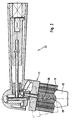
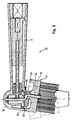
- a brush part 1 is shown, which on the handle part and the drive shaft the above electric toothbrush can be plugged on.
- the Brush part 1 has a carrier tube 2 which extends in the direction of a longitudinal axis 3 extends.
- the carrier tube 2 is at its free facing the handle part End provided with a profile ring 4, which has an inner contour 5, which to the The outer contour of the handle part is complementary. In this way, the brush part 1 are attached to the handle in a rotationally fixed manner.
- a shaft 7 is rotatably mounted.
- the shaft 7 is arranged in the longitudinal axis 3 of the support tube 2 and preferably consists of Metal.
- the shaft 7 extends from the bore 6 in the Handle part facing direction about to the middle of the support tube 2.
- a further shaft 8 connected, which is arranged in the longitudinal axis 3 and preferably made of plastic consists.
- the further shaft 8 has on the handle part facing free end of an inner contour 9 that leads to the outer contour of the grip part outstanding drive shaft is complementary. In this way, the Drive shaft rotatably with the further shaft 8 and thus also with the shaft 7 get connected.
- the inner and outer contours 5, 9 can - seen in cross section - are square, star-shaped or similar contours that are so close together are adapted that on the one hand a simple plugging and unplugging the Brush part 1 of the handle part is possible by a user, but on the other hand the secure fit of the brush part 1 on the handle part is guaranteed.
- a shell on the support tube 2 10 attached.
- this shell 10 there are also a bristle carrier 11 and means for coupling the bristle carrier 11 to the shaft 7 and the Carrier tube 2 arranged.
- the bristle carrier 11 has a disc-shaped plate 12 and a continuous one Bore 13 and is essentially rotationally symmetrical to one Brush axis 14 designed.
- the Plate 12 On its side facing away from the shaft 7 is the Plate 12 provided with a plurality of bristles 15 which are in a to the brush axis 14 project approximately parallel direction from the plate 12.
- the bristles 15 can preferably be about the same length, so that their free ends are about form circular cleaning surface 16.
- the bore 13 in the plate 12 is aligned approximately parallel to the brush axis 14 and aims approximately in the center the cleaning surface 16.
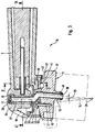
- the bore 6 is made in a bearing bush 17, which is also a has continuous bore 18 transverse to the bore 6.
- the bore 6 is thus aligned approximately parallel to the longitudinal axis 3, while the bore 18 approximately is arranged parallel to a transverse axis 19 perpendicular thereto.
- the in the Bore 6 mounted shaft 7 does not extend into the area of bore 18.
- the shaft 7 carries a pinion 20, the is rotatably connected to the shaft 7. It is understood that instead of the pinion 20 a crown gear, a bevel gear or the like can also be provided.
- a bearing pin 21 is rotatably mounted on the End facing away from the bristle carrier 11 with a head or a disk 22 is secured against falling out.
- a crown gear 23 rotatably connected. This is achieved, for example, in that the crown gear 23 on the Bearing pin 21 is attached with a press fit.
- the pinion 20 and that Crown gear 23 mesh with one another.
- other components can also be provided, for example a Bevel gear or the like.
- the bearing pin 21 is a wedge disk 24 connected in a rotationally fixed manner, the bearing pin 21 being approximately at the center of the Wedge washer 24 is pressed into this, for example.
- the gearbox can Made of metal or plastic. In the latter case, it is appropriate to Shafts 7, 8 and the pinion 20, as well as crown gear 23 and wedge disk 24 as to manufacture one-piece injection molded part.
- Another bearing pin 25 is eccentric to the bearing pin 21 in the wedge disk 24 held non-rotatably, for example pressed.
- This bearing pin 25 serves the rotatable Storage of the bristle carrier 11 by being in the bore 13 of the plate 12 is recorded.
- the bearing pin 25 is thus arranged in the brush axis 14.
- the further bearing pin has 25 a disc 26 or a head, which prevents the Prevent bristle carrier 11.
- the further bearing pin 25 carries a bearing disc between the components mentioned 27 or the like.
- this bearing disc 27 can also be omitted.
- the bearing pin 21 and thus the transverse axis 19 are approximately at right angles to the arranged facing surface of the wedge 24, during the further bearing pin 25 and thus the brush axis 14 approximately at right angles to the other surface of the wedge disk 24 facing them are arranged.
- the Wedge washer 24 is thus designed such that its surfaces in one Angles 28 are arranged to each other.
- the two Bearing pins 21, 25 and thus the transverse axis 19 and the brush axis 14 enclose said angle 28 with each other.
- the angle 28 goes from an apex 29 in which the transverse axis 19 and the brush axis 14 cut.
- a groove on the side of the carrier tube 2 facing the bristle carrier 11 30 is provided, arranged in the longitudinal direction starting from the transverse axis 19 is. Furthermore, a finger 31 protrudes from the bristle carrier 11, which extends into the Groove 30 engages and can slide back and forth in this.
- the Bristle carrier 11 makes a nutation movement about the transverse axis 19. This means that the cleaning surface 16 of the bristle carrier 11 forming free ends of the bristles 15 are set in a stroke or impact movement, the direction of these lifting or pushing movements being substantially parallel is aligned to the bristles and thus approximately parallel to the brush axis 14.
- the stroke or impact movements act in the direction of the tooth surfaces this tooth 32 and ensure a particularly effective cleaning of the Teeth of plaque and the like
- the angle 28 is approximately 6 degrees, preferably 3 degrees.
- the apex 29 is approximately in the region of the tooth 32 is arranged. In this way, the tooth surfaces to be cleaned become all-round detected by the described lifting or impact movements of the bristles 15.
- the angle 28 in the brush part 33 of FIG. 2 about 10 degrees, preferably 5 degrees.
- a vertex 29 lies in this embodiment outside the tooth 32, but is arranged in the vicinity thereof.
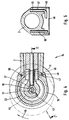
- the brush part 34 shown in FIGS. 3 to 6 has, inter alia, the the following significant differences from those based on FIGS. 1 and 2 described Brush parts 1, 33.
- the two bearing pins 21, 25 replaced by a cranked shaft 35, and on the other hand is 30 instead of the groove and the finger 31 a retaining spring 36 is provided.
- Retaining spring instead of Retaining spring also other components, such as. B. articulated lever, cords or other Elastomer parts are used.
- the shaft 35 has a region 37 which is in the bore 18 the bearing bush 17 arranged in the transverse axis 19 and rotatably supported there is.
- This area 37 of the shaft 35 carries the crown gear 23, which rotates with the Shaft 35 is connected.
- the crank of the shaft 35 is in the area of the wedge disk 24 arranged so that it is also rotatably connected to the shaft 35.
- the shaft 35 has an area 38 which is in the bore 13 of the Plate 12 is arranged in the brush axis 14 and is rotatably supported there.
- the Both free ends of the shaft 35 are provided with disks 39, 40, each prevent falling out.
- the shaft 35 is preferably made of a curved one Made of round metal.
- the holding spring 36 consists of a metal wire and connects the bristle carrier 11 with the carrier tube 2.
- the shape of the retaining spring 36 can be seen. So is 3 that an area 41 of the retaining spring 36 is inserted into a blind hole 42 in the plate 12 of the bristle carrier 11. After that 6, there follows an approximately right-angled bend 43, after which the retaining spring 36 merges into a spring region 44.
- At the other end of the spring area 44 is an approximately rectangular one Bend 45 is provided in such a way that the subsequent area 46 in has a direction opposite to region 41. This is particularly out the fig. 5 and 6 can be seen. 5, the area 46 is in a blind hole 47 of the carrier tube 2 inserted. Approximately symmetrical to the blind hole 47 a cylindrical pin 56 is pressed into the carrier tube 2.
- the bristle carrier 11 In the switched-on state, the bristle carrier 11 is placed in a wobble or Offset nutation movement. With a direction of rotation 58 of the shaft 35 subsides the retaining spring 36 on the cylinder pin 56. In this way it becomes a self-rotation of the bristle holder 11 by the connection of the bristle holder 11 and of the support tube 2 prevented via the retaining spring 36.
- the movements of the Bristle carrier 11 with respect to the carrier tube 2 are elastic Rotational and / or bending deformation, in particular of the spring region 44 of the retaining spring 36 balanced.
- the pressed-in cylinder pin 56 by a stop integrally formed on the carrier tube 2 or similar constructive Measures to be replaced.
- FIGS. 3 to 6 Another difference of the brush part 34 according to FIGS. 3 to 6 to the Brush parts 1, 33 according to FIGS. 1 and 2 consists in the design of the mutually assigned surfaces of the bristle carrier 11 and the carrier tube 2.
- one is the support tube 2 facing surface 48 of the plate 12 of the bristle carrier 11 spherical configured, the center of the ball being arranged at the apex 29.
- the remaining self-rotation if any, depends on the force dependent, with which the user places the bristles 15 on the tooth 32.
- By Applying a fairly high force can make the user self-rotating practically completely prevent.
- the brush part 51 results in 3 shows a nutation movement with superimposed, free or uncontrolled self-rotation of the bristle carrier 11, its frequency depends on the pressure exerted by the user.
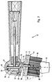
- the brush part 52 shown in FIG. 8 has instead of the means for prevention a self-rotation of the bristle carrier 11 means for generating a such self-rotation.
- the brush part 52 of FIG. 8 is a controlled or positively controlled Self-rotation of the bristle carrier 11.
- a bevel gear toothing running around 360 degrees 53 provided on the side of the bristle carrier 11 facing the carrier tube 2 on the outer edge of the plate 12 . Furthermore, the bristle carrier 11 faces Side of the support tube 2 and the shell 10 also one to 360 degrees revolving bevel gear teeth 54 are arranged.
- the two bevel gear teeth 53, 54 are assigned to each other and mesh with each other, the Engagement of the bevel gear teeth 53, 54 rotates.
- the bristle carrier 11 In the switched-on state, the bristle carrier 11 wobbles out. At the same time the two bevel gear teeth 53, 54 Self-rotation of the bristle carrier 11 generated about the brush axis 14. The speed of rotation this self-rotation depends on the tooth conditions of the two bevel gear teeth 53, 54.
Claims (22)
- Elément de brossage (1, 33, 51, 52) pour une brosse à dents électrique, comportant un tube porteur (2) dans lequel est installé un arbre (7) monté, de façon à pouvoir tourner, autour d'un axe longitudinal (3), et comportant un support de poils (11), présentant un axe de brosse (14), dont des poils (15) font saillie et qui est monté de façon à pouvoir tourner autour d'un axe transversal (19) et qui est accouplé à l'arbre (7), dans lequel un mouvement de rotation de l'arbre (7) autour de l'axe longitudinal (3) provoque un mouvement du support de poils (11) par rapport à l'axe transversal (19), et comportant des moyens (24, 25; 35, 38) pour le mouvement de l'axe de brosse (14) du support de poils (11) sensiblement sur une enveloppe conique, caractérisé en ce que l'axe transversal (19) et l'axe de brosse (14) forment un angle aigu (28) autour d'un point sommital (29).
- Elément de brossage suivant la revendication 1, caractérisé en ce que le point sommital (29) est agencé en dehors de la zone de poils formée par les poils (15).
- Elément de brossage suivant la revendication 2, caractérisé en ce que, lorsque des poils (15) sont appliqués sur une dent (32) à nettoyer, le point sommital (29) est situé dans la dent (32).
- Elément de brossage suivant la revendication 1, caractérisé en ce que le point sommital (29) est agencé dans la zone de poils formée par les poils (15), le point sommital (29) étant situé au voisinage d'une surface de nettoyage (16) des poils (15).
- Elément de brossage suivant l'une des revendications 1 à 4, caractérisé en ce que l'angle (28) présente une valeur dans la plage d'approximativement 2 degrés jusqu'à approximativement 14 degrés, en particulier d'approximativement 6 degrés jusqu'à approximativement 10 degrés, de préférence d'approximativement 3 degrés à approximativement 5 degrés.
- Elément de brossage suivant l'une des revendications 1 à 5, caractérisé en ce que l'arbre (7) porte une roue dentée, en particulier un pignon (20) ou un élément semblable, reliée fixement en rotation et qui entre en prise avec une roue dentée, en particulier une roue en couronne (23) ou un élément semblable, montée de façon à pouvoir tourner autour de l'axe transversal (19).
- Elément de brossage suivant la revendication 6, caractérisé en ce qu'une broche de palier (21) est montée de façon à pouvoir tourner dans le tube porteur (2) qui est relié fixement en rotation à la roue en couronne (23) ou à l'élément semblable.
- Elément de brossage suivant la revendication 6, caractérisé en ce qu'il est prévu un arbre (35) en particulier coudé, en particulier en métal rond plié, qui est relié de façon fixe en rotation à la roue en couronne (23) ou à un élément semblable par une zone (37) et qui est monté de façon à pouvoir tourner dans le tube porteur (2).
- Elément de brossage suivant l'une des revendications 7 et 8, caractérisé en ce que le support de poils (11) est relié par une plaque en coin (24) à la roue en couronne (23) ou à un élément semblable.
- Elément de brossage suivant l'une des revendications 7 à 9, caractérisé en ce que le support de poils (11) est monté, de façon à pouvoir tourner, au moyen d'une autre broche de palier (25) ou au moyen d'une autre zone (38) de l'arbre (35).
- Elément de brossage suivant l'une des revendications 1 à 10, caractérisé en ce que sont prévus des moyens (30, 31) qui empêchent un mouvement de rotation du support de poils (11) autour de l'axe de brosse (14).
- Elément de brossage suivant la revendication 11, caractérisé en ce que le tube porteur (2) présente une rainure (30) qui s'étend radialement par rapport à l'axe de brosse (14) et dans laquelle entre en prise une excroissance (31) qui fait saillie du support de poils (11).
- Elément de brossage suivant la revendication 11, caractérisé en ce que les moyens sont réalisés sous la forme d'un ressort de retenue, d'un lever articulé, de cordons, d'autres éléments en élastomère ou d'autres éléments semblables.
- Elément de brossage suivant la revendication 13, caractérisé en ce que le ressort de retenue (36) présente deux zones (41, 46) pliées approximativement à angle droit ainsi qu'une zone de ressort (44) située là entre.
- Elément de brossage suivant la revendication 14, caractérisé en ce que le ressort de retenue (36) est constitué par un fil métallique et en ce que les deux zones (41, 46) du ressort de retenue (36) sont enfoncées dans des trous borgnes (42, 47) du support de poils (11) et du tube porteur (2).
- Elément de brossage suivant l'une des revendications 1 à 10, caractérisé en ce que sont prévus des moyens (53, 54) qui provoquent un mouvement de rotation du support de poils (11) autour de l'axe de brosse (14).
- Elément de brossage suivant la revendication 16, caractérisé en ce que le tube porteur (2) et support de poils (11) présentent chacun une denture de roue conique (53, 54) qui entrent en prise l'une avec l'autre.
- Elément de brossage suivant l'une des revendications 1 à 17, caractérisé en ce que les surfaces (48, 49, 50) associées l'une à l'autre du tube porteur (2) et du support de poils (11) sont bombées de même manière.
- Elément de brossage suivant la revendication 18, caractérisé en ce que la surface (48) du support de poils (11), la surface (49) du tube porteur (2) et, le cas échéant, une surface (50) d'une coque (10) raccordée au tube porteur (2) sont façonnées en forme sphérique et présentent un centre de sphère commun.
- Elément de brossage suivant la revendication 19, caractérisé en ce que le centre de sphère est agencé au point sommital (29).
- Brosse à dents électrique comportant un élément de brossage (1, 51, 52), qui peut être accouplé, en particulier qui peut être enfiché, suivant l'une des revendications précédentes.
- Brosse à dents électrique suivant la revendication 21, caractérisée en ce qu'il est prévu un entraínement qui tourne en continu.
Applications Claiming Priority (3)
| Application Number | Priority Date | Filing Date | Title |
|---|---|---|---|
| DE4438732A DE4438732A1 (de) | 1994-10-29 | 1994-10-29 | Bürstenteil für eine elektrische Zahnbürste |
| DE4438732 | 1994-10-29 | ||
| PCT/EP1995/003255 WO1996013224A1 (fr) | 1994-10-29 | 1995-08-16 | Element de brossage pour une brosse a dents electrique |
Publications (2)
| Publication Number | Publication Date |
|---|---|
| EP0794743A1 EP0794743A1 (fr) | 1997-09-17 |
| EP0794743B1 true EP0794743B1 (fr) | 1999-01-13 |
Family
ID=6532039
Family Applications (1)
| Application Number | Title | Priority Date | Filing Date |
|---|---|---|---|
| EP95929885A Expired - Lifetime EP0794743B1 (fr) | 1994-10-29 | 1995-08-16 | Element de brossage pour une brosse a dents electrique |
Country Status (12)
| Country | Link |
|---|---|
| US (1) | US5862558A (fr) |
| EP (1) | EP0794743B1 (fr) |
| JP (1) | JP3710096B2 (fr) |
| KR (1) | KR100352326B1 (fr) |
| CN (1) | CN1050277C (fr) |
| AT (1) | ATE175566T1 (fr) |
| AU (1) | AU3346595A (fr) |
| CA (1) | CA2201469C (fr) |
| DE (2) | DE4438732A1 (fr) |
| DK (1) | DK0794743T3 (fr) |
| ES (1) | ES2129219T3 (fr) |
| WO (1) | WO1996013224A1 (fr) |
Families Citing this family (56)
| Publication number | Priority date | Publication date | Assignee | Title |
|---|---|---|---|---|
| US6171268B1 (en) * | 1998-09-28 | 2001-01-09 | Eli Zhadanov | Attachment for a rotatable device for washing, cleaning, massaging, etc. |
| USD456998S1 (en) | 1999-01-25 | 2002-05-14 | Lawrence A. Blaustein | Head portion of an electric toothbrush |
| DE19934805C2 (de) * | 1999-07-28 | 2001-10-18 | Moser Elektrogeraete Gmbh | Zahnbürste mit Exzenterantrieb |
| AR027180A1 (es) * | 1999-07-28 | 2003-03-19 | Moser Elektrogeraete Gmbh | Un cepillo dental con un mecanismo de impulsion excentrico |
| US6447293B1 (en) * | 1999-08-13 | 2002-09-10 | Water Pik, Inc. | Drive mechanism for interproximal flossing device |
| US6574820B1 (en) | 1999-10-22 | 2003-06-10 | The Gillette Company | Brush head for toothbrush |
| WO2001060281A1 (fr) | 2000-02-15 | 2001-08-23 | Glaxosmithkline Consumer Healthcare Gmbh & Co Kg | Partie brosse d'une brosse a dents electrique |
| US6490747B1 (en) | 2000-03-20 | 2002-12-10 | Maged Metwally | Electric toothbrush attachment |
| US6347425B1 (en) | 2000-06-28 | 2002-02-19 | Colgate-Palmolive Company | Powered toothbrush having three dimensional rotational head motion |
| US20050008986A1 (en) * | 2000-08-10 | 2005-01-13 | Gary Sokol | Multi-directional motion flosser |
| USD484311S1 (en) | 2001-01-12 | 2003-12-30 | Water Pik, Inc. | Disposable toothbrush |
| US6581234B2 (en) | 2001-04-02 | 2003-06-24 | Jin Po Lee | Dental brush unit comprising gear connections |
| ATE298540T1 (de) * | 2001-04-03 | 2005-07-15 | Wik Far East Ltd | Elektrische zahnbürste |
| US6721986B2 (en) * | 2001-06-28 | 2004-04-20 | Qingping Zhuan | Electric toothbrush |
| EP1404245A4 (fr) | 2001-07-12 | 2006-04-05 | Water Pik Inc | Dispositif d'hygiene buccale a deux moteurs |
| DE10206493A1 (de) * | 2002-02-16 | 2003-08-28 | Braun Gmbh | Zahnbürste |
| DK1424955T3 (da) * | 2001-09-14 | 2008-11-17 | Braun Gmbh | Tandbörste |
| US7640614B2 (en) * | 2001-11-06 | 2010-01-05 | The Procter & Gamble Company | Multi motion toothbrush |
| MXPA04004247A (es) * | 2001-11-06 | 2004-07-08 | Procter & Gamble | Cepillo dental de movimiento multiple. |
| US20030084525A1 (en) * | 2001-11-07 | 2003-05-08 | The Procter & Gamble Company | Complex motion toothbrush |
| USD499884S1 (en) | 2002-03-15 | 2004-12-21 | The Procter & Gamble Company | Electric toothbrush |
| US6799346B2 (en) * | 2002-01-04 | 2004-10-05 | Atico International Usa, Inc. | Toothbrush with oppositely reciprocating brush heads |
| USD487349S1 (en) | 2002-02-01 | 2004-03-09 | Water Pik, Inc. | Dental device |
| US20030163882A1 (en) | 2002-03-04 | 2003-09-04 | The Procter & Gamble Company | Electric toothbrushes |
| US7266855B2 (en) * | 2002-06-04 | 2007-09-11 | Qingping Zhuan | Electric toothbrush |
| US6931688B2 (en) * | 2002-08-09 | 2005-08-23 | Colgate-Palmolive Company | Toothbrush |
| US20040134001A1 (en) * | 2002-09-13 | 2004-07-15 | The Procter & Gamble Company | Toothbrushes with a replaceable head having a threaded connection |
| JP4306230B2 (ja) * | 2002-11-13 | 2009-07-29 | パナソニック電工株式会社 | 電動歯ブラシ |
| US7636976B2 (en) * | 2002-12-30 | 2009-12-29 | The Procter & Gamble Company | Power toothbrush |
| US7198487B2 (en) * | 2002-12-31 | 2007-04-03 | Water Pik, Inc. | Whitening tip for dental flossing device |
| US7320691B2 (en) * | 2003-01-15 | 2008-01-22 | Pacific Bioscience Laboratories, Inc. | Apparatus and method for acoustic/mechanical treatment of early stage acne |
| US20040177458A1 (en) | 2003-03-10 | 2004-09-16 | The Procter & Gamble Company | Electric toothbrushes |
| US7302726B2 (en) * | 2003-05-23 | 2007-12-04 | Braun Gmbh | Toothbrushes |
| BRPI0417211A (pt) * | 2003-12-19 | 2007-02-06 | Procter & Gamble | escova de dentes elétrica |
| US7861348B2 (en) * | 2004-12-08 | 2011-01-04 | The Procter & Gamble Company | Electric toothbrushes |
| US8056176B2 (en) | 2007-01-25 | 2011-11-15 | The Procter & Gamble Company | Toothbrushes |
| US7954196B1 (en) | 2008-03-14 | 2011-06-07 | Michele Rene Nault-Richter | Mini multitask brush |
| EP2184033A1 (fr) * | 2008-11-05 | 2010-05-12 | Braun Gmbh | Brosse à dents électrique et sa brosse |
| US8302239B2 (en) * | 2009-07-10 | 2012-11-06 | Igor Lantsberg | Orbital electric toothbrush |
| JP5477050B2 (ja) * | 2010-02-26 | 2014-04-23 | オムロンヘルスケア株式会社 | 偏心ロッドの固定構造および振動発生装置 |
| EP2550895A2 (fr) | 2010-03-24 | 2013-01-30 | Hint Co. Ltd. | Brosse à dents rotative |
| CN103732175B (zh) | 2011-05-02 | 2016-12-14 | 沃特皮克公司 | 机械驱动式声波牙刷 |
| WO2014145890A2 (fr) | 2013-03-15 | 2014-09-18 | Water Pik, Inc. | Brosse à dents sonique entraînée mécaniquement et nettoyeur inter-dentaire à eau |
| US9468511B2 (en) | 2013-03-15 | 2016-10-18 | Water Pik, Inc. | Electronic toothbrush with vibration dampening |
| EP2821029B1 (fr) * | 2013-07-02 | 2016-10-12 | Braun GmbH | Instrument d'hygiène personnelle et dispositif d'hygiène personnelle |
| US10772473B2 (en) * | 2014-08-13 | 2020-09-15 | Nse Products, Inc. | Device and method for cleansing and treating skin |
| CN106998970A (zh) | 2014-08-13 | 2017-08-01 | Nse 产品公司 | 用于清洁和护理皮肤的装置和方法 |
| EP3106125A1 (fr) * | 2015-06-17 | 2016-12-21 | Braun GmbH | Instrument d'hygiène buccale et procédé d'assemblage d'un instrument d'hygiène buccale |
| CN205568226U (zh) | 2015-07-08 | 2016-09-14 | 洁碧有限公司 | 刷牙装置 |
| US10561480B2 (en) | 2016-05-09 | 2020-02-18 | Water Pik, Inc. | Load sensing for oral devices |
| USD844997S1 (en) | 2016-12-15 | 2019-04-09 | Water Pik, Inc. | Toothbrush handle |
| AU2017378474B2 (en) | 2016-12-15 | 2022-06-02 | Water Pik, Inc. | Brushing device with illumination features |
| USD845636S1 (en) | 2016-12-15 | 2019-04-16 | Water Pik, Inc. | Toothbrush handle |
| ES2843001T3 (es) * | 2017-03-31 | 2021-07-15 | Trisa Holding Ag | Cepillo eléctrico para el aseo corporal |
| US20220175505A1 (en) * | 2020-12-03 | 2022-06-09 | Macksoud Khan | Powered toothbrush with complex movement |
| US20230046428A1 (en) * | 2021-08-12 | 2023-02-16 | Jon Welsh | Electric Toothbrush Device |
Family Cites Families (4)
| Publication number | Priority date | Publication date | Assignee | Title |
|---|---|---|---|---|
| DE3931982A1 (de) * | 1989-09-26 | 1991-04-11 | Alexander Dipl I Muehlhaeusser | Elektromotorisch angetriebenes geraet |
| DE3937850A1 (de) * | 1989-11-14 | 1991-05-16 | Braun Ag | Elektrische zahnbuerste mit drehbarem borstentraeger |
| DE4239251A1 (de) * | 1992-11-21 | 1994-05-26 | Braun Ag | Elektrische Zahnbürste mit drehbarem Borstenträger |
| IT1261901B (it) * | 1993-02-26 | 1996-06-03 | Ariete Srl | Spazzolino da denti,antiplacca,motorizzato. |
-
1994
- 1994-10-29 DE DE4438732A patent/DE4438732A1/de not_active Ceased
-
1995
- 1995-08-16 KR KR1019970702313A patent/KR100352326B1/ko not_active IP Right Cessation
- 1995-08-16 JP JP51427396A patent/JP3710096B2/ja not_active Expired - Fee Related
- 1995-08-16 CA CA002201469A patent/CA2201469C/fr not_active Expired - Fee Related
- 1995-08-16 ES ES95929885T patent/ES2129219T3/es not_active Expired - Lifetime
- 1995-08-16 DE DE59504842T patent/DE59504842D1/de not_active Expired - Fee Related
- 1995-08-16 AT AT95929885T patent/ATE175566T1/de not_active IP Right Cessation
- 1995-08-16 WO PCT/EP1995/003255 patent/WO1996013224A1/fr active IP Right Grant
- 1995-08-16 EP EP95929885A patent/EP0794743B1/fr not_active Expired - Lifetime
- 1995-08-16 AU AU33465/95A patent/AU3346595A/en not_active Abandoned
- 1995-08-16 DK DK95929885T patent/DK0794743T3/da active
- 1995-08-16 CN CN95195826A patent/CN1050277C/zh not_active Expired - Fee Related
-
1997
- 1997-03-25 US US08/823,413 patent/US5862558A/en not_active Expired - Fee Related
Also Published As
| Publication number | Publication date |
|---|---|
| DE4438732A1 (de) | 1996-05-02 |
| WO1996013224A1 (fr) | 1996-05-09 |
| JP3710096B2 (ja) | 2005-10-26 |
| DK0794743T3 (da) | 1999-09-06 |
| CA2201469C (fr) | 2002-11-05 |
| AU3346595A (en) | 1996-05-23 |
| US5862558A (en) | 1999-01-26 |
| CA2201469A1 (fr) | 1996-05-09 |
| DE59504842D1 (de) | 1999-02-25 |
| JPH10507671A (ja) | 1998-07-28 |
| KR970705949A (ko) | 1997-11-03 |
| ES2129219T3 (es) | 1999-06-01 |
| CN1161643A (zh) | 1997-10-08 |
| ATE175566T1 (de) | 1999-01-15 |
| CN1050277C (zh) | 2000-03-15 |
| KR100352326B1 (ko) | 2002-12-18 |
| EP0794743A1 (fr) | 1997-09-17 |
Similar Documents
| Publication | Publication Date | Title |
|---|---|---|
| EP0794743B1 (fr) | Element de brossage pour une brosse a dents electrique | |
| EP0537465B1 (fr) | Brosse à dents dont la tête est munie d'au moins un support de brosse monté sur palier et pouvant être entraîné en rotation | |
| EP0818977B1 (fr) | Brosse pour brosse a dents electrique | |
| EP0793456B1 (fr) | Partie de brosse pour brosse a dents electrique | |
| EP0793455B1 (fr) | Element de brossage pour une brosse a dents electrique | |
| EP0624079B1 (fr) | Brosse a dents electrique a porte-soies rotatif | |
| EP0977521B1 (fr) | PARTIE DE BROSSE POUR BROSSE à DENTS ELECTRIQUE | |
| EP1489989B1 (fr) | Brosse a dents electrique | |
| DE2736286A1 (de) | Mechanische zahnbuerste und verfahren zu ihrer anwendung | |
| EP0765642B1 (fr) | Tête de brosse pour une brosse à dents électrique | |
| DE19803311A1 (de) | Elektrische Zahnbürste | |
| DE19701964A1 (de) | Elektrische Zahnbürste | |
| DE4243219A1 (de) | Elektromechanische Zahnbürste | |
| DE102010035045A1 (de) | Piezomotor | |
| EP3262976B1 (fr) | Brosse | |
| DE4318976C2 (de) | Elektromechanische Zahnbürste | |
| DE19521302C1 (de) | Bürstenteil für eine elektrische Zahnbürste | |
| EP2428183A1 (fr) | Brosse à dents mécanique et son mécanisme d entraînement | |
| DE10315011A1 (de) | Elektrische Zahnbürste | |
| DE2932295C2 (fr) | ||
| EP1614399A2 (fr) | Transmission pour modifier un mouvement linéaire oscillatoire ainsi que brosse à dent électrique équipée d'une telle transmission | |
| DE102004060781B4 (de) | Elektrische Zahnbürste | |
| DE2726451C3 (de) | Antrieb zum Erzeugen von Drehschwingungen bei einem Gerät zur medizinischen Körperpflege, insbesondere bei einer Zahnbürste | |
| EP0785050A2 (fr) | Brosse de rinçage avec une poignée pivotante | |
| EP3748202A1 (fr) | Dispositif de pivotement ou de serrage d'un composant |
Legal Events
| Date | Code | Title | Description |
|---|---|---|---|
| PUAI | Public reference made under article 153(3) epc to a published international application that has entered the european phase |
Free format text: ORIGINAL CODE: 0009012 |
|
| 17P | Request for examination filed |
Effective date: 19970213 |
|
| AK | Designated contracting states |
Kind code of ref document: A1 Designated state(s): AT BE CH DE DK ES FR GB GR IE IT LI NL PT SE |
|
| 17Q | First examination report despatched |
Effective date: 19971110 |
|
| GRAG | Despatch of communication of intention to grant |
Free format text: ORIGINAL CODE: EPIDOS AGRA |
|
| GRAG | Despatch of communication of intention to grant |
Free format text: ORIGINAL CODE: EPIDOS AGRA |
|
| GRAH | Despatch of communication of intention to grant a patent |
Free format text: ORIGINAL CODE: EPIDOS IGRA |
|
| GRAG | Despatch of communication of intention to grant |
Free format text: ORIGINAL CODE: EPIDOS AGRA |
|
| GRAH | Despatch of communication of intention to grant a patent |
Free format text: ORIGINAL CODE: EPIDOS IGRA |
|
| GRAG | Despatch of communication of intention to grant |
Free format text: ORIGINAL CODE: EPIDOS AGRA |
|
| GRAH | Despatch of communication of intention to grant a patent |
Free format text: ORIGINAL CODE: EPIDOS IGRA |
|
| GRAH | Despatch of communication of intention to grant a patent |
Free format text: ORIGINAL CODE: EPIDOS IGRA |
|
| GRAA | (expected) grant |
Free format text: ORIGINAL CODE: 0009210 |
|
| AK | Designated contracting states |
Kind code of ref document: B1 Designated state(s): AT BE CH DE DK ES FR GB GR IE IT LI NL PT SE |
|
| PG25 | Lapsed in a contracting state [announced via postgrant information from national office to epo] |
Ref country code: IT Free format text: LAPSE BECAUSE OF FAILURE TO SUBMIT A TRANSLATION OF THE DESCRIPTION OR TO PAY THE FEE WITHIN THE PRE;WARNING: LAPSES OF ITALIAN PATENTS WITH EFFECTIVE DATE BEFORE 2007 MAY HAVE OCCURRED AT ANY TIME BEFORE 2007. THE CORRECT EFFECTIVE DATE MAY BE DIFFERENT FROM THE ONE RECORDED.SCRIBED TIME-LIMIT Effective date: 19990113 Ref country code: GR Free format text: LAPSE BECAUSE OF NON-PAYMENT OF DUE FEES Effective date: 19990113 |
|
| REF | Corresponds to: |
Ref document number: 175566 Country of ref document: AT Date of ref document: 19990115 Kind code of ref document: T |
|
| REG | Reference to a national code |
Ref country code: CH Ref legal event code: EP |
|
| REG | Reference to a national code |
Ref country code: CH Ref legal event code: NV Representative=s name: LUCHS & PARTNER PATENTANWAELTE |
|
| GBT | Gb: translation of ep patent filed (gb section 77(6)(a)/1977) |
Effective date: 19990113 |
|
| REG | Reference to a national code |
Ref country code: IE Ref legal event code: FG4D Free format text: GERMAN |
|
| REF | Corresponds to: |
Ref document number: 59504842 Country of ref document: DE Date of ref document: 19990225 |
|
| PG25 | Lapsed in a contracting state [announced via postgrant information from national office to epo] |
Ref country code: PT Free format text: LAPSE BECAUSE OF FAILURE TO SUBMIT A TRANSLATION OF THE DESCRIPTION OR TO PAY THE FEE WITHIN THE PRESCRIBED TIME-LIMIT Effective date: 19990413 |
|
| ET | Fr: translation filed | ||
| REG | Reference to a national code |
Ref country code: ES Ref legal event code: FG2A Ref document number: 2129219 Country of ref document: ES Kind code of ref document: T3 |
|
| PG25 | Lapsed in a contracting state [announced via postgrant information from national office to epo] |
Ref country code: IE Free format text: LAPSE BECAUSE OF NON-PAYMENT OF DUE FEES Effective date: 19990820 |
|
| REG | Reference to a national code |
Ref country code: DK Ref legal event code: T3 |
|
| REG | Reference to a national code |
Ref country code: IE Ref legal event code: FD4D |
|
| PLBE | No opposition filed within time limit |
Free format text: ORIGINAL CODE: 0009261 |
|
| STAA | Information on the status of an ep patent application or granted ep patent |
Free format text: STATUS: NO OPPOSITION FILED WITHIN TIME LIMIT |
|
| RAP2 | Party data changed (patent owner data changed or rights of a patent transferred) |
Owner name: BRAUN GMBH |
|
| 26N | No opposition filed | ||
| NLT2 | Nl: modifications (of names), taken from the european patent patent bulletin |
Owner name: BRAUN GMBH |
|
| REG | Reference to a national code |
Ref country code: FR Ref legal event code: CD Ref country code: FR Ref legal event code: CA |
|
| REG | Reference to a national code |
Ref country code: CH Ref legal event code: PFA Free format text: BRAUN AKTIENGESELLSCHAFT TRANSFER- BRAUN AKTIENGESELLSCHAFT;BRAUN GMBH |
|
| REG | Reference to a national code |
Ref country code: GB Ref legal event code: IF02 |
|
| PGFP | Annual fee paid to national office [announced via postgrant information from national office to epo] |
Ref country code: ES Payment date: 20040806 Year of fee payment: 10 |
|
| PGFP | Annual fee paid to national office [announced via postgrant information from national office to epo] |
Ref country code: FR Payment date: 20040820 Year of fee payment: 10 Ref country code: AT Payment date: 20040820 Year of fee payment: 10 |
|
| PGFP | Annual fee paid to national office [announced via postgrant information from national office to epo] |
Ref country code: SE Payment date: 20040823 Year of fee payment: 10 |
|
| PGFP | Annual fee paid to national office [announced via postgrant information from national office to epo] |
Ref country code: BE Payment date: 20040824 Year of fee payment: 10 |
|
| PGFP | Annual fee paid to national office [announced via postgrant information from national office to epo] |
Ref country code: CH Payment date: 20040826 Year of fee payment: 10 |
|
| PGFP | Annual fee paid to national office [announced via postgrant information from national office to epo] |
Ref country code: DK Payment date: 20040830 Year of fee payment: 10 |
|
| PGFP | Annual fee paid to national office [announced via postgrant information from national office to epo] |
Ref country code: GB Payment date: 20050718 Year of fee payment: 11 |
|
| PGFP | Annual fee paid to national office [announced via postgrant information from national office to epo] |
Ref country code: DE Payment date: 20050729 Year of fee payment: 11 |
|
| PGFP | Annual fee paid to national office [announced via postgrant information from national office to epo] |
Ref country code: NL Payment date: 20050812 Year of fee payment: 11 |
|
| PG25 | Lapsed in a contracting state [announced via postgrant information from national office to epo] |
Ref country code: AT Free format text: LAPSE BECAUSE OF NON-PAYMENT OF DUE FEES Effective date: 20050816 |
|
| PG25 | Lapsed in a contracting state [announced via postgrant information from national office to epo] |
Ref country code: SE Free format text: LAPSE BECAUSE OF NON-PAYMENT OF DUE FEES Effective date: 20050817 Ref country code: ES Free format text: LAPSE BECAUSE OF NON-PAYMENT OF DUE FEES Effective date: 20050817 |
|
| PG25 | Lapsed in a contracting state [announced via postgrant information from national office to epo] |
Ref country code: LI Free format text: LAPSE BECAUSE OF NON-PAYMENT OF DUE FEES Effective date: 20050831 Ref country code: DK Free format text: LAPSE BECAUSE OF NON-PAYMENT OF DUE FEES Effective date: 20050831 Ref country code: CH Free format text: LAPSE BECAUSE OF NON-PAYMENT OF DUE FEES Effective date: 20050831 Ref country code: BE Free format text: LAPSE BECAUSE OF NON-PAYMENT OF DUE FEES Effective date: 20050831 |
|
| REG | Reference to a national code |
Ref country code: CH Ref legal event code: PL |
|
| REG | Reference to a national code |
Ref country code: DK Ref legal event code: EBP |
|
| EUG | Se: european patent has lapsed | ||
| PG25 | Lapsed in a contracting state [announced via postgrant information from national office to epo] |
Ref country code: FR Free format text: LAPSE BECAUSE OF NON-PAYMENT OF DUE FEES Effective date: 20060428 |
|
| REG | Reference to a national code |
Ref country code: FR Ref legal event code: ST Effective date: 20060428 |
|
| REG | Reference to a national code |
Ref country code: ES Ref legal event code: FD2A Effective date: 20050817 |
|
| PG25 | Lapsed in a contracting state [announced via postgrant information from national office to epo] |
Ref country code: NL Free format text: LAPSE BECAUSE OF NON-PAYMENT OF DUE FEES Effective date: 20070301 Ref country code: DE Free format text: LAPSE BECAUSE OF NON-PAYMENT OF DUE FEES Effective date: 20070301 |
|
| GBPC | Gb: european patent ceased through non-payment of renewal fee |
Effective date: 20060816 |
|
| NLV4 | Nl: lapsed or anulled due to non-payment of the annual fee |
Effective date: 20070301 |
|
| PG25 | Lapsed in a contracting state [announced via postgrant information from national office to epo] |
Ref country code: GB Free format text: LAPSE BECAUSE OF NON-PAYMENT OF DUE FEES Effective date: 20060816 |
|
| BERE | Be: lapsed |
Owner name: *BRAUN A.G. Effective date: 20050831 |