EP0794593A2 - Durch die Bewegung eines äusseren Körpers lösbarer Schnellkupplungsverbinder mit automatischer Verriegelung - Google Patents
Durch die Bewegung eines äusseren Körpers lösbarer Schnellkupplungsverbinder mit automatischer Verriegelung Download PDFInfo
- Publication number
- EP0794593A2 EP0794593A2 EP97102771A EP97102771A EP0794593A2 EP 0794593 A2 EP0794593 A2 EP 0794593A2 EP 97102771 A EP97102771 A EP 97102771A EP 97102771 A EP97102771 A EP 97102771A EP 0794593 A2 EP0794593 A2 EP 0794593A2
- Authority
- EP
- European Patent Office
- Prior art keywords
- female element
- female
- male
- fingers
- retaining
- Prior art date
- Legal status (The legal status is an assumption and is not a legal conclusion. Google has not performed a legal analysis and makes no representation as to the accuracy of the status listed.)
- Withdrawn
Links
Images

Classifications
-
- H—ELECTRICITY
- H01—ELECTRIC ELEMENTS
- H01R—ELECTRICALLY-CONDUCTIVE CONNECTIONS; STRUCTURAL ASSOCIATIONS OF A PLURALITY OF MUTUALLY-INSULATED ELECTRICAL CONNECTING ELEMENTS; COUPLING DEVICES; CURRENT COLLECTORS
- H01R13/00—Details of coupling devices of the kinds covered by groups H01R12/70 or H01R24/00 - H01R33/00
- H01R13/02—Contact members
- H01R13/20—Pins, blades, or sockets shaped, or provided with separate member, to retain co-operating parts together
Definitions
- the invention relates to a fast coupling or quick-coupling connector fitted with a sliding safety sleeve or body, which prevents accidental release thereof.
- the connector is particularly suitable for monopole or multipolar screened/shielded cables.
- connectors of this type are commonly used for radio aerials, telephony etc. In these fields the need is felt for a connector which allows the electrical connection of two parts simply by a fast and easy operation of moving together, and which nevertheless does not allow the two parts to separate except through a deliberate action by the user.
- the aim of the present invention is to avoid the disadvantages of the prior art and achieve the aims specified above.
- the connector comprises a female element, a male element and a body.
- the female element made of conductive metal sheet or pipe, has a portion formed by fins or fingers having a certain elasticity, normally spread apart when no external forces are applied.
- the fingers have retaining teeth extending inwards.
- the male element has a shoulder surface for engagement of the teeth of the female element.
- one element, male or female may contain internally one or more plugs and vice versa the other element, female or male, can carry the respective sockets.
- the body has a housing for the female element, comprising a first and a second communicating chambers, the first chamber being able to house the female element in a widened or spread apart condition and the second chamber housing the female element in a narrow, forced condition. Insertion of the male element with the shoulder surface beyond the retaining teeth automatically locks the male element and the female element in a connected or wired position. Release or disconnection may only be achieved by sliding the body along the female element in such a way that the latter occupies the wide or second chamber and may spread therein, releasing the engagement of the teeth from the shoulder surface of the male element which can therefore be extracted.
- the new connector overcomes the drawbacks of the prior art, comprises a reduced number of parts, can be produced at low cost and is convenient to use; moreover, once it has been locked up, it ensures contact pressure between the male and female elements; this contact pressure between the male and female elements is particularly effective with the connector in the inserted condition and may be eliminated in the unlocked position.
- the new connector is suitable for use with shielded cables.
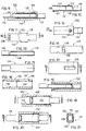
- a first embodiment of the connector which is denoted overall by reference numeral 10.
- the connector 10 comprises a female element 12, a male element 14 and a sleeve or body element 16.
- the male and female elements are made of a conductive material, and the body can be made of metal or plastic.
- additional electrical connection means generally comprising plugs and sockets, may be placed some internally integral with the female element 12 and others internally integral with the male element 14, and are not shown in the accompanying drawings. Likewise electric cables joined to the male element and to the female element are not shown.
- the female element 12 as shown in greater detail in Figs. 2 and 3, comprises a tubular part made of conductive wound sheet or pipe and a retaining part 20 having fins or fingers integral with the tubular part 18.
- the fingers 21 of the part 20 may be two or more, preferably, in the embodiment shown, three identical fingers are evenly arranged around the central longitudinal axis a of the female element.
- Each fin or finger preferably has a shape with a slanting surface 22 adjacent to the tubular part 18, a curved surface 24 which ensures the necessary contact pressure, with the connector in inserted condition, and a surface portion 26 from which a retaining tooth 28 projects inwards. Generally there is only one retaining tooth 28 for each finger, but there may be more on each one.
- the retaining tooth is preferably obtained by punch-cutting three sides thereof out of a sheet which makes up the finger, the fourth side remaining joined to act as a hinge for the tooth.
- the part 20 with fingers has on each finger an end surface widening outwards and referenced 30.
- the wings are separated by slots denoted by 32, preferably extending as far as the root of the fingers, where they are joined to the tubular part 18.
- the material whereof the female element is composed (generally conductive sheet metal) is sufficiently elastic for the fingers, in a condition with no external forces, to have an outwardly widened or spread apart position, as shown in Figs. 2 and 3.
- the male element in the embodiment of said figures, consists of a substantially cylindrical body 34, with an annular projection 36 projecting from the body.
- the projection preferably has a frustoconical surface 37 towards the end of the male element intended to be housed in the female element, and a retaining surface 38 or retaining shoulder, opposite the surface 37.
- the distance d between the end of the male element intended to be housed in the female element and the surface 38 is not greater than the distance D between the end of the teeth of the female element and the root of the fingers, or joining surface of the fingers and the tubular part.
- the body element or sleeve 16 is formed with an internal axial through housing which comprises three communicating chambers, referenced 40, 42 and 44 respectively.
- the chamber 44 has such a diameter as to be able to house the tubular part 18 of the female element.
- the chamber 42 has such internal dimensions as to be able to house the part 20 of the female element in a contracted or tightened condition.
- the chamber 40 has such a diameter as to be able to house the part 28 of the fingers of the female element in the spread apart condition.
- a frustoconical surface 45 between the chambers 42, 44 is intended to house and support the surface 22 of the female element.
- a frustoconical surface 46 between the chamber 40 and the chamber 42 is intended to house and support the surface 30 of the fingers in a contracted condition.
- a shoulder surface 48 on an internal projecting part 47 of the distal end of the body 16, towards the interior of same, is intended to provide an abutment for the limit position of the body in respect of the female element, so that the latter cannot be disengaged accidentally therefrom.
- Longitudinal slots 49 in the chamber 40 are provided to allow the body element to disengage from the manufacturing mould during manufacture thereof.
- a peripheral groove 50 can be provided externally on the body to allow the user to grip it easily with his fingers.
- the female element 12 is assembled to the body element 16 by inserting from the end shown on the right in the drawings and then by pushing it as far as the position illustrated in Fig. 1, wherein the surface 22 of the fingers is placed against the surface 45 of the body, and the portion 26 of the fingers is placed against the surface 43 of the chamber 42, which forces the fingers into a closed or gathered position.
- the male element 14 can be connected easily and simply by bringing the assembly 12, 16 and the male element 14 close one to the other along the axis a and inserting the male element in the assembly 12, 16.
- the male element by entering with the annular projection 36, elastically pushes the teeth 28 outwards until the projection 36 goes beyond the teeth themselves, which then spring into their extended position engaging the shoulder surface 38 and preventing extraction of the male element 14.
- An identical result can be obtained if the element 12 is inserted in the element 16 in such a way that the part 30 goes beyond the shoulder 48 (Fig. 8), and the male element 14 is inserted as shown in Fig. 8.
- the three elements will be assembled in a non-detachable manner as shown in Fig. 6, more specifically a reciprocal pull applied on the element 14 and element 12, or on cables connected thereto, does not cause release of the connection.
- the body element 16 has to be made to slide along the axis a in respect of the female element 12, in the position shown in Fig. 8. That is to say the operator holds the element 14 in one hand and pulls, with the other hand, the body element 16 to the left in the drawings.
- This manoeuvre means that the part 28 of the fingers of the female element occupies the larger diameter chamber 40, of the body, so that the fingers spread apart elastically to an adequate extent for the teeth to disengage the shoulder 38 of the male element, which can therefore be removed from the female element.
- the reciprocal position of the female element and of the body has a limit in the reciprocal engaging of the distal end 30 of the fingers and of the shoulder surface 48 of the body.
- the maximum diameter ⁇ 1 of the annular projection 36 of the male element must not be greater than the diameter ⁇ 2 defined by the innermost ends of the teeth 28 of the female element, in a non-forced condition of the teeth 28 and of the fingers 21.
- the shown embodiment may entail a number of variants, for example instead of three there may be two or four fingers, or as required.
- the connector 100 comprises a female element 112, a male element 114 and a locking sleeve or body element 116.
- the female element 112 in conductive metal sheet is in this case formed with a tubular part 118 with a quadrangular section, and if necessary a part with deformable tongues 119, which may be clipped onto the cable.
- the female element also comprises a part 120 having fingers, in this case formed by two elastically deformable and facing flat fingers 121, 121', the finger 121' having an elastic tooth 128 protruding towards the other finger.
- the fingers 121, 121' are joined to the tubular section 118.
- the tooth 128 is preferably formed by punch cutting in the finger 121'.
- An elastic stop tooth 122 is formed in the tubular portion 118 and extends outwards. The width of the tubular portion extends slightly beyond the width of the fingers to form shoulder surfaces 130.
- the male element 114 is preferably also formed from bent metal sheet, in this case with a quadrangular section, and comprises distal tongues 134 for crimping to a cable and a tubular part, in one of whose walls an aperture 136 is made to form a shoulder surface 138.
- the body 116 in this embodiment has a substantially rectangular form viewed from the ends and a through hole or through longitudinal housing therein comprises consecutive chambers 140, 142 whereof the chamber 140 houses the distal ends of the fingers of the female element in a spread apart condition, and the chamber 142 houses the fingers in the retracted and contracted condition.
- abutment surfaces 148 for preventing extraction and accidental disengaging of the female element from the body are formed between the chambers 140 and 142, and are intended for being engaged by the shoulders 130 of the female element, as can be seen in Fig. 20.
- One wall of the body has a longitudinally elongated aperture 147, one of whose walls 145 co-operates with the tooth 122 to prevent extraction from the body 116 of the female element 112 to the right in the drawings.
- the female element is assembled to the body by inserting it, with the fingers contracted, via the right-hand end until the surfaces 130, 148 engage one with the other.
- the male element With the female element in the condition of Fig. 19, that is to say with spread apart fingers, the male element is inserted and the tooth 128 engages against the shoulder 138, when the fingers move into the adjacent or contracted position, so as to lock the male element inside the female element (Fig. 9). Extraction can only take place after sliding of the body element 116 in respect of the female element 112 from the position of Figs. 9 and 18 to the position of Figs. 19 and 20, wherein the fingers 121, 121' spread apart, leaving the male element free.
- plastic body particularly in the second embodiment, may be moulded or made in any way in a multiple form, to house similar contacts or contacts with different features.
- the male and female elements may have a polygonal section instead of a rectangular or circular one.
- the shape of the male and female elements contributes to forming complete screening using monopole or multipolar screened cables.
Landscapes
- Details Of Connecting Devices For Male And Female Coupling (AREA)
Applications Claiming Priority (3)
| Application Number | Priority Date | Filing Date | Title |
|---|---|---|---|
| ITMI960428 | 1996-03-05 | ||
| IT96MI000428A IT1283191B1 (it) | 1996-03-05 | 1996-03-05 | Connettore a innesto rapido con impegno automatico e disimpegno mediante movimento di un corpo esterno |
| US08/905,925 US6039614A (en) | 1996-03-05 | 1997-08-05 | Fast coupling automatic latching connector releasable by movement of an external body |
Publications (2)
| Publication Number | Publication Date |
|---|---|
| EP0794593A2 true EP0794593A2 (de) | 1997-09-10 |
| EP0794593A3 EP0794593A3 (de) | 1998-12-02 |
Family
ID=26331363
Family Applications (1)
| Application Number | Title | Priority Date | Filing Date |
|---|---|---|---|
| EP97102771A Withdrawn EP0794593A3 (de) | 1996-03-05 | 1997-02-20 | Durch die Bewegung eines äusseren Körpers lösbarer Schnellkupplungsverbinder mit automatischer Verriegelung |
Country Status (3)
| Country | Link |
|---|---|
| US (1) | US6039614A (de) |
| EP (1) | EP0794593A3 (de) |
| IT (1) | IT1283191B1 (de) |
Families Citing this family (20)
| Publication number | Priority date | Publication date | Assignee | Title |
|---|---|---|---|---|
| US5985356A (en) * | 1994-10-18 | 1999-11-16 | The Regents Of The University Of California | Combinatorial synthesis of novel materials |
| EP0968547B1 (de) * | 1997-03-25 | 2005-08-10 | Radi Medical Systems Ab | Weiblicher steckverbinder |
| ATE305177T1 (de) * | 1999-07-08 | 2005-10-15 | Whitaker Corp | Elektrischer steckverbinder für koaxialkabel |
| DE10248809A1 (de) * | 2002-10-19 | 2004-04-29 | Robert Bosch Gmbh | Elektrischer Steckverbinder in der Ausgestaltung eines Buchsenkontakts mit spezieller Lamellengestaltung |
| JP4312619B2 (ja) * | 2004-01-28 | 2009-08-12 | 日本圧着端子製造株式会社 | 雌コンタクト |
| US9065207B2 (en) * | 2008-03-14 | 2015-06-23 | Zonit Structured Solutions, Llc | Locking electrical receptacle |
| US10297958B2 (en) * | 2007-03-14 | 2019-05-21 | Zonit Structured Solutions, Llc | Locking electrical receptacle with elongate clamping surfaces |
| DE102008061934B4 (de) * | 2008-12-12 | 2011-02-24 | Tyco Electronics Amp Gmbh | Hochstromsteckverbinder |
| US7658657B1 (en) | 2009-02-26 | 2010-02-09 | Hubbell Incorporated | Single-pole electrical connector having a steel retaining spring |
| US8137125B2 (en) * | 2009-02-26 | 2012-03-20 | Hitachi Cable, Ltd. | Conductor connection structure |
| US8840436B2 (en) | 2011-05-05 | 2014-09-23 | Lear Corporation | Electrically conducting terminal |
| US8876562B2 (en) | 2011-05-05 | 2014-11-04 | Lear Corporation | Female type contact for an electrical connector |
| US9325095B2 (en) | 2011-05-05 | 2016-04-26 | Lear Corporation | Female type contact for an electrical connector |
| US8808039B2 (en) | 2011-08-22 | 2014-08-19 | Lear Corporation | Connector assembly and terminal retainer |
| US8858264B2 (en) | 2012-11-28 | 2014-10-14 | Lear Corporation | Electrical terminal retainer and receptacle assembly |
| US8926360B2 (en) | 2013-01-17 | 2015-01-06 | Cooper Technologies Company | Active cooling of electrical connectors |
| US9093764B2 (en) * | 2013-01-17 | 2015-07-28 | Cooper Technologies Company | Electrical connectors with force increase features |
| TWM463920U (zh) * | 2013-02-08 | 2013-10-21 | Chun Nien Plastic Led | 線插座之供插頭安全插組結構 |
| US11581682B2 (en) | 2013-03-15 | 2023-02-14 | Zonit Structured Solutions, Llc | Frictional locking receptacle with programmable release |
| JP6725562B2 (ja) * | 2018-03-01 | 2020-07-22 | 矢崎総業株式会社 | 接続端子 |
Citations (5)
| Publication number | Priority date | Publication date | Assignee | Title |
|---|---|---|---|---|
| FR1284586A (fr) * | 1961-01-02 | 1962-02-16 | Mti Le Materiel Tech Ind | Borne de raccordement à un conducteur en languette |
| US3538486A (en) * | 1967-05-25 | 1970-11-03 | Amp Inc | Connector device with clamping contact means |
| FR2082873A6 (de) * | 1970-03-31 | 1971-12-10 | Electr Entreprises | |
| US4632121A (en) * | 1985-09-18 | 1986-12-30 | Tronomed, Inc. | Safety medical cable assembly with connectors |
| US5024608A (en) * | 1989-01-30 | 1991-06-18 | Societe Anonyme Dite: Cegelec | Connection device for a coaxial cable and a corresponding connection module, in particular a junction block |
Family Cites Families (4)
| Publication number | Priority date | Publication date | Assignee | Title |
|---|---|---|---|---|
| US2567727A (en) * | 1949-04-07 | 1951-09-11 | American Phenolic Corp | Connector having an automatic locking sleeve |
| US3171183A (en) * | 1961-06-20 | 1965-03-02 | James R Johnston | Utility fastener |
| US3569903A (en) * | 1969-08-07 | 1971-03-09 | Sealectro Corp | Coaxial connector with axial interlock |
| US5332394A (en) * | 1993-10-12 | 1994-07-26 | The Bg Service Co., Inc. | Electrical connector for connecting a voltage source to a spark plug terminal |
-
1996
- 1996-03-05 IT IT96MI000428A patent/IT1283191B1/it active IP Right Grant
-
1997
- 1997-02-20 EP EP97102771A patent/EP0794593A3/de not_active Withdrawn
- 1997-08-05 US US08/905,925 patent/US6039614A/en not_active Expired - Fee Related
Patent Citations (5)
| Publication number | Priority date | Publication date | Assignee | Title |
|---|---|---|---|---|
| FR1284586A (fr) * | 1961-01-02 | 1962-02-16 | Mti Le Materiel Tech Ind | Borne de raccordement à un conducteur en languette |
| US3538486A (en) * | 1967-05-25 | 1970-11-03 | Amp Inc | Connector device with clamping contact means |
| FR2082873A6 (de) * | 1970-03-31 | 1971-12-10 | Electr Entreprises | |
| US4632121A (en) * | 1985-09-18 | 1986-12-30 | Tronomed, Inc. | Safety medical cable assembly with connectors |
| US5024608A (en) * | 1989-01-30 | 1991-06-18 | Societe Anonyme Dite: Cegelec | Connection device for a coaxial cable and a corresponding connection module, in particular a junction block |
Also Published As
| Publication number | Publication date |
|---|---|
| EP0794593A3 (de) | 1998-12-02 |
| US6039614A (en) | 2000-03-21 |
| ITMI960428A0 (de) | 1996-03-05 |
| ITMI960428A1 (it) | 1997-09-05 |
| IT1283191B1 (it) | 1998-04-16 |
Similar Documents
| Publication | Publication Date | Title |
|---|---|---|
| US6039614A (en) | Fast coupling automatic latching connector releasable by movement of an external body | |
| US7128595B2 (en) | Electrical connector with positive lock | |
| US6083030A (en) | Connector latch | |
| US4940424A (en) | Electrical plug accessory | |
| EP2950401B1 (de) | Elektrischer steckverbinder | |
| EP0585633B1 (de) | Verriegelbare elektrische Steckkupplung | |
| US6361348B1 (en) | Right angle, snap on coaxial electrical connector | |
| US7862366B2 (en) | Electrical connector with locking clip | |
| JP2008530754A (ja) | スナップロック接続端子 | |
| JP5572335B2 (ja) | 自動固定コネクターシステム用雌型連結器 | |
| GB2130026A (en) | Electric connector | |
| EP2754210B1 (de) | Sicherer elektrischer behälter | |
| CA2927747A1 (en) | Push lock electrical connector | |
| US3474398A (en) | Releasable locking connector | |
| US4148538A (en) | Elastomeric electrical connector | |
| CA2225602C (en) | Connector and connector kit | |
| US6722922B2 (en) | Heavy duty electrical connector | |
| US8435061B2 (en) | Connector | |
| EP0795937B1 (de) | Elektrischer Steckverbinder und Montur | |
| WO1997017742A1 (en) | Connector latch and assembly | |
| US6273741B1 (en) | Locking connector for antenna cable | |
| US6027356A (en) | Connector assembly | |
| CN217009728U (zh) | 一种带保护壳的塑料扣连接器 | |
| CA1130403A (en) | Extension cord lock___ | |
| EP0986140A2 (de) | Elektrische Kontaktbuchse |
Legal Events
| Date | Code | Title | Description |
|---|---|---|---|
| PUAI | Public reference made under article 153(3) epc to a published international application that has entered the european phase |
Free format text: ORIGINAL CODE: 0009012 |
|
| AK | Designated contracting states |
Kind code of ref document: A2 Designated state(s): DE ES FR GB |
|
| PUAL | Search report despatched |
Free format text: ORIGINAL CODE: 0009013 |
|
| AK | Designated contracting states |
Kind code of ref document: A3 Designated state(s): DE ES FR GB |
|
| STAA | Information on the status of an ep patent application or granted ep patent |
Free format text: STATUS: THE APPLICATION IS DEEMED TO BE WITHDRAWN |
|
| 18D | Application deemed to be withdrawn |
Effective date: 19990302 |