EP0794473B1 - An image forming apparatus - Google Patents
An image forming apparatus Download PDFInfo
- Publication number
- EP0794473B1 EP0794473B1 EP97103569A EP97103569A EP0794473B1 EP 0794473 B1 EP0794473 B1 EP 0794473B1 EP 97103569 A EP97103569 A EP 97103569A EP 97103569 A EP97103569 A EP 97103569A EP 0794473 B1 EP0794473 B1 EP 0794473B1
- Authority
- EP
- European Patent Office
- Prior art keywords
- toner
- image
- charging
- magnetic brush
- image forming
- Prior art date
- Legal status (The legal status is an assumption and is not a legal conclusion. Google has not performed a legal analysis and makes no representation as to the accuracy of the status listed.)
- Expired - Lifetime
Links
Images


Classifications
-
- G—PHYSICS
- G03—PHOTOGRAPHY; CINEMATOGRAPHY; ANALOGOUS TECHNIQUES USING WAVES OTHER THAN OPTICAL WAVES; ELECTROGRAPHY; HOLOGRAPHY
- G03G—ELECTROGRAPHY; ELECTROPHOTOGRAPHY; MAGNETOGRAPHY
- G03G21/00—Arrangements not provided for by groups G03G13/00 - G03G19/00, e.g. cleaning, elimination of residual charge
- G03G21/0005—Arrangements not provided for by groups G03G13/00 - G03G19/00, e.g. cleaning, elimination of residual charge for removing solid developer or debris from the electrographic recording medium
- G03G21/0064—Arrangements not provided for by groups G03G13/00 - G03G19/00, e.g. cleaning, elimination of residual charge for removing solid developer or debris from the electrographic recording medium using the developing unit, e.g. cleanerless or multi-cycle apparatus
-
- G—PHYSICS
- G03—PHOTOGRAPHY; CINEMATOGRAPHY; ANALOGOUS TECHNIQUES USING WAVES OTHER THAN OPTICAL WAVES; ELECTROGRAPHY; HOLOGRAPHY
- G03G—ELECTROGRAPHY; ELECTROPHOTOGRAPHY; MAGNETOGRAPHY
- G03G15/00—Apparatus for electrographic processes using a charge pattern
- G03G15/02—Apparatus for electrographic processes using a charge pattern for laying down a uniform charge, e.g. for sensitising; Corona discharge devices
- G03G15/0208—Apparatus for electrographic processes using a charge pattern for laying down a uniform charge, e.g. for sensitising; Corona discharge devices by contact, friction or induction, e.g. liquid charging apparatus
- G03G15/0216—Apparatus for electrographic processes using a charge pattern for laying down a uniform charge, e.g. for sensitising; Corona discharge devices by contact, friction or induction, e.g. liquid charging apparatus by bringing a charging member into contact with the member to be charged, e.g. roller, brush chargers
- G03G15/0225—Apparatus for electrographic processes using a charge pattern for laying down a uniform charge, e.g. for sensitising; Corona discharge devices by contact, friction or induction, e.g. liquid charging apparatus by bringing a charging member into contact with the member to be charged, e.g. roller, brush chargers provided with means for cleaning the charging member
-
- G—PHYSICS
- G03—PHOTOGRAPHY; CINEMATOGRAPHY; ANALOGOUS TECHNIQUES USING WAVES OTHER THAN OPTICAL WAVES; ELECTROGRAPHY; HOLOGRAPHY
- G03G—ELECTROGRAPHY; ELECTROPHOTOGRAPHY; MAGNETOGRAPHY
- G03G15/00—Apparatus for electrographic processes using a charge pattern
- G03G15/02—Apparatus for electrographic processes using a charge pattern for laying down a uniform charge, e.g. for sensitising; Corona discharge devices
- G03G15/0208—Apparatus for electrographic processes using a charge pattern for laying down a uniform charge, e.g. for sensitising; Corona discharge devices by contact, friction or induction, e.g. liquid charging apparatus
- G03G15/0241—Apparatus for electrographic processes using a charge pattern for laying down a uniform charge, e.g. for sensitising; Corona discharge devices by contact, friction or induction, e.g. liquid charging apparatus by bringing charging powder particles into contact with the member to be charged, e.g. by means of a magnetic brush
-
- G—PHYSICS
- G03—PHOTOGRAPHY; CINEMATOGRAPHY; ANALOGOUS TECHNIQUES USING WAVES OTHER THAN OPTICAL WAVES; ELECTROGRAPHY; HOLOGRAPHY
- G03G—ELECTROGRAPHY; ELECTROPHOTOGRAPHY; MAGNETOGRAPHY
- G03G2215/00—Apparatus for electrophotographic processes
- G03G2215/00025—Machine control, e.g. regulating different parts of the machine
- G03G2215/00029—Image density detection
- G03G2215/00033—Image density detection on recording member
- G03G2215/00037—Toner image detection
- G03G2215/0005—Toner image detection without production of a specific test patch
-
- G—PHYSICS
- G03—PHOTOGRAPHY; CINEMATOGRAPHY; ANALOGOUS TECHNIQUES USING WAVES OTHER THAN OPTICAL WAVES; ELECTROGRAPHY; HOLOGRAPHY
- G03G—ELECTROGRAPHY; ELECTROPHOTOGRAPHY; MAGNETOGRAPHY
- G03G2215/00—Apparatus for electrophotographic processes
- G03G2215/02—Arrangements for laying down a uniform charge
- G03G2215/021—Arrangements for laying down a uniform charge by contact, friction or induction
- G03G2215/022—Arrangements for laying down a uniform charge by contact, friction or induction using a magnetic brush
-
- G—PHYSICS
- G03—PHOTOGRAPHY; CINEMATOGRAPHY; ANALOGOUS TECHNIQUES USING WAVES OTHER THAN OPTICAL WAVES; ELECTROGRAPHY; HOLOGRAPHY
- G03G—ELECTROGRAPHY; ELECTROPHOTOGRAPHY; MAGNETOGRAPHY
- G03G2221/00—Processes not provided for by group G03G2215/00, e.g. cleaning or residual charge elimination
- G03G2221/0005—Cleaning of residual toner
Definitions
- the present invention relates to an image forming apparatus provided with a charging device the contactable to an image bearing member to charge the image bearing member.
- An electrophotographic apparatus wherein an image bearing member such as a photosensitive member is charged by a magnetic brush contact charging device.
- the contact charging device has an advantage that amount of the ozone product is smaller than a corona discharger.
- the contact charging involves a problem that if the toner particles are introduced into the magnetic brush, the charging property of the charging device is deteriorated, since the magnetic particles forming the magnetic brush are electroconductive, whereas the toner particles of the toner image formed on the image bearing member are insulative.
- the cleaning for removing residual toner from the photosensitive member after image transfer is not used for purpose of downsizing of the image forming apparatus, and such toner is removed by the developing device, then amount of the introduced toner is large since a large amount of the toner reaches the charging position of the charging device.
- the toner mixing amount is further large with the result of remarkable deterioration of the charging property.
- the amount of introduced toner varies depending on image forming conditions, and the charging property is different depending on the amount of introduced toner.
- a contact charging device directly injects the charge into the charge injection layer provided at the photosensitive member surface. Therefore, the deterioration of the charging property resulting from the toner introduction is more significant than in the normal charging type using electric discharge.
- the deterioration of the charging property results in image defect in the resultant image.
- Document EP-A-0 622 703 discloses an image forming apparatus using a contact-type charger to charge a photoreceptor.
- Document JP 06-266266 A discloses an image forming apparatus comprising a cleaning member in the vicinity of the magnetic brush to collect toner therefrom.
- Document JP 06-230654 A discloses to detect electrostatic charging performance of a magnetic brush charging means by detecting a current.
- Figure 1 is a schematic illustration of an image forming apparatus according to an example not covered by the claims.
- Figure 2 is a graph showing a photosensitive member potential obtained by charging current measurement in a first example not covered by the claims.
- Figure 3 is a graph of a relation between the toner amount in the magnetic brush charging device and the current in the first example not covered by the claims.
- Figure 4 is a graph showing a relation between an applied voltage and a surface potential of the photosensitive member in an injection charging type.
- Figure 5 is a schematic illustration of an example of color image forming apparatus according to an embodiment of the present invention.
- Figure 6 is a graph showing a charging DC bias and a charged potential according to a first embodiment.
- Figure 7 is a graph showing a relation between an amount of introduced toner in the magnetic brush charging device and a charged potential in an injection charging type.
- Figure 8 is a schematic illustration of an image forming apparatus according to a third embodiment.
- Figure 9 is a schematic view of a magnetic brush charging device of a rotatable sleeve type.
- Figure 10 is a flow chart for an AC bias control used in the third embodiment.
- Figure 11 is a flow chart for an AC bias control used in the third embodiment.
- Figure 12 is a flow chart for an AC bias control used in a fifth embodiment.
- Figure 13 is a graph of an example of a relation between a toner amount in a magnetic brush charging device and an AC bias in the fifth embodiment.
- Figure 14 is a timing chart in a cleaning mode.
- Figure 15 is a flow chart for determining setting in a cleaning mode.
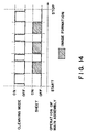
- Figure 16 is a timing chart of a cleaning mode used in an apparatus according to a seventh embodiment.
- Figure 17 shows a relation between a charging AC bias and a charged potential of the photosensitive member.
- Figure 18 shows a relation between a charging AC bias and a charged potential of the photosensitive member.
- This example relates to an image forming apparatus wherein an untransferred toner is at least temporarily collected in a magnetic brush charging device, and a toner amount in the magnetic brush is predicted or estimated on the basis of a current through the magnetic brush charging device, and the setting of the image forming process condition of the image forming apparatus is changed.
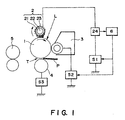
- FIG. 1 is a schematic illustration of an image forming apparatus according to an example not covered by the claims.
- the image forming apparatus in this example is a laser beam printer using an electrophotographic process.
- Designated by 1 is an electrophotographic photosensitive member of a rotatable drum type as an image bearing member.
- the photosensitive member 1 is rotated in the clockwise direction indicated by the arrow.
- the photosensitive drum 1 comprises an electroconductive base of metal or the like which is electrically grounded, and a photosensitive layer.
- the photosensitive layer is an organic photoconductive layer having a negative charging polarity.
- Designated by 2 is a contact charging device using a magnetic brush contacted to the photosensitive member 1, and it comprises a rotatable non-magnetic electrode sleeve 21, a magnet 22, and an electroconductive magnetic particles 23 deposited on the sleeve by the magnetic force of the magnet 22.
- the sleeve 21 for the magnetic brush 2 is supplied with a charging bias voltage comprising a DC bias(negative polarity) and an AC bias superposed thereon from a charging bias applying voltage source S1 to uniformly charge the outer peripheral surface of the photosensitive member 1.
- a detecting device 24 for detecting a current through the magnetic brush is provided, and a process condition for image formation is changed in accordance with the current detected thereby.
- the volume resistivity of the magnetic particle 23 is preferably 1x 10 5 -1x 10⁸ ⁇ cm.
- the charged surface of the photosensitive member 1 is exposed to scanning exposure L emitted from a laser beam modulated in the intensity, corresponding to the pixel signal, so that electrostatic latent image is formed on the peripheral surface of the rotatable photosensitive member 1 in accordance with the intended image information.
- the electrostatic latent image is developed into a toner image with an insulative toner(negative charging polarity) by a developing bias applied from the developing bias applying voltage source S2.
- the volume resistivity of the toner is preferably not less than 1x 10 15 ⁇ cm.
- a transfer material P as a recording material is supplied from an unshown sheet feeding station, and is introduced at a predetermined. timing into a nip(transfer portion)T formed between the photosensitive member 1 and a transfer roller 4 as a contact type transferring means which is contacted thereto at a predetermined pressure and which has an intermediate resistance.
- a transfer bias voltage(positive polarity) of the polarity opposite from that of the toner is applied from a transfer bias application voltage source S3, so that charge of the polarity opposite from that of the toner charge is applied to the back side of the transfer material.
- the transfer material P introduced to the transfer portion T is passed through the nip, and the toner image is continuously transferred from the surface of the photosensitive member 1 onto the transfer material P by the electrostatic force and the pressure.
- the residual toner remaining on the photosensitive member after the image transfer is partly charged to the positive polarity by the transfer charging.
- the transfer material P now having the toner image is separated from the surface of the photosensitive member 1, and is fed to a heat fixing type fixing device 5, where the toner image is fixed on the transfer material P. Finally, it is discharged as a print.
- the surface of the photosensitive member after-the toner image transfer to the transfer material P reaches the position where it is contacted to the magnetic brush charging device 2, while carrying the untransferred toner.
- the untransferred toner is partly taken up by sliding force and the charging bias(negative) of the magnetic brush, so that surface is cleaned to be used again for the image formation.
- those charged to the negative polarity passes through the contact portion, but those charged to the positive polarity is attracted into the magnetic brush.
- the photosensitive member region having the untransferred toner is charged by the charging device, and then, is exposed to an image so that latent image is formed.
- the untransferred toner introduced into the magnetic brush charging device 2 is charged by the friction with the magnetic particles 23 to the negative polarity which is the normal charging polarity, and is discharged uniformly onto the surface of the photosensitive member, and is then collected by the developing device 3 at a developing station to be reused for the development.
- the developing bias of the developing device is so selected that negative residual toner is removed, while the normal is effected. More particularly, it is selected to be between the dark portion potential and the light portion potential, by which an electric field is formed in such a direction that toner is deposited from the developing sleeve to the light potential portion, whereas the toner returns from the dark potential portion to the developing sleeve.
- the polarity of the untransferred toner is uniformed to the normal negative polarity by the charging device 2, so that pattern of the untransferred toner is removed, thus preventing production of the remaining image.
- the description will be made as to a device for detecting a physical quantity relating to the toner amount to predict the toner amount in the magnetic brush charging device used in this example.
- the magnetic brush charger of this example comprises, as shown in Figure 1, a rotatable non-magnetic electrode sleeve 21, a magnet 22, and magnetic particles 23 deposited by the magnetic force on the sleeve.
- the magnetic brush charging device 2 is supplied with the charging bias in the form of the DC voltage biased with the AC bias voltage from the charging bias applying voltage source S1, and the detecting device 24 is provided between the magnetic brush charging device 2 and the charging bias voltage source S1 to detect the DC current through the magnetic brush.
- the potential difference between the magnetic brush and the photosensitive member 1 is made constant.
- the potential difference from the photosensitive member is not constant because of the change of the image ratio and/or the transfer voltage. Therefore, the current detection is not carried out during the image forming operation, and is carried out when the image is not formed, with the potential of the photosensitive member being kept constant.
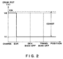
- the photosensitive member is subjected to a whole surface exposure to uniform laser beam L when the image forming operation is not carried out, and the developing bias applying voltage source S2 and the transfer bias application voltage source S3 are rendered off, and a predetermined voltage Vdc is applied to the sleeve 21, while the light portion potential of the photosensitive member is V1.
- the DC current supplied to the sleeve 21 is then measured.
- the measured current(a physical quantity relating to the toner amount) is compared with a relation, as shown in Figure 3, between the toner amount in the magnetic brush charging device and the current, which relation has been measured beforehand. And, the toner amount in the magnetic brush charging device 2 is determined therein as the toner amount for the measured potential difference(Vdc-V1).
- a processing device 6 determines image forming process conditions such as the charging bias and developing bias, and changes the process conditions accordingly.
- image forming process conditions such as the charging bias and developing bias
- the charging bias is in the form of an AC biased DC voltage, and the discharging thereby is used.
- the present invention is not limited to a particular charging type, and is applicable to a magnetic brush charging device of any injection charging type wherein the charge is directly injected into a charge injection layer of a photosensitive member.
- the charge injection is directly effected by a contact charging member having an intermediate resistance into the photosensitive member surface not through discharge phenomenon. Therefore, the photosensitive member is charged to a potential corresponding to the applied voltage to the charging member, even if the applied voltage is lower than the discharge threshold.
- a relation between the applied voltage and the surface potential of the photosensitive member is shown in Figure 4 (when the toner is not introduced into the charger).
- the charge injection layer in this example is produced as follows. SnO 2 particles having a particle size of approx. 0.03 ⁇ m made electroconductive by antimony-doping, are dispersed in photo-curing type acrylic resin material at 5:2 parts by weight, and 3 parts by weight of Teflon particles having a particle size of 0.5 ⁇ m are added thereto. The material thus produced is applied on the OPC photosensitive layer through dip coating method. The thickness thereof is 3 ⁇ m.
- the volume resistivity of the charge injection layer is preferably in the range of 1x 10 10 -1x 10 14 ⁇ cm, and is further preferably 1x 10 12 -1x 10 13 ⁇ cm under the normal temperature and normal humidity condition (23.5°C, 60%), if the resistance change under high temperature and high humidity and low temperature low humidity conditions are taken into account.
- the volume resistivity of the charge injection layer is measured, using a sample thereof in the form of a sheet and a HIGH RESISTANCE METER 4329A (available from Yokogawa Hewlett-Packard Kabushiki Kaisha, Japan) connected to a RESISTIVITY CELL 16008A, with a voltage of 100V applied.
- a HIGH RESISTANCE METER 4329A available from Yokogawa Hewlett-Packard Kabushiki Kaisha, Japan
- the control of this example can be used with such an injection charging type image forming apparatus by measuring the DC current through the magnetic brush charging device.
- an image forming apparatus wherein the untransferred toner is at least temporarily collected by the magnetic brush charging device, the toner amount in the magnetic brush is predicted on the basis of the current through the magnetic brush charging device, and in accordance with the predicted toner amount, the image forming process condition of the image forming apparatus is changed, or the image forming operation is prohibited, so that production of defective image due to the deterioration of the charging performance can be prevented beforehand.
- This example provides an image forming apparatus wherein the untransferred toner is at least temporarily collected by a magnetic brush charging device, wherein a cleaning bias is applied to the magnetic brush charging device so as to return a part of toner from the charging device to the photosensitive member, and a toner content on the photosensitive member at this time(a physical quantity relating to the amount of introduced toner) is measured.
- the toner amount in the magnetic brush is predicted on the basis of the measurement, and the process condition of the image forming apparatus is set in accordance with the prediction.
- the image forming operation is prohibited.
- Figure 5 is a schematic illustration of an image forming apparatus according to an embodiment of the present invention.
- the image forming apparatus is a color image forming apparatus using an electrophotographic process.
- the color image forming apparatus of this example is provided with a plurality of photosensitive members for the purpose of high speed color image output, wherein a transfer material is fed by a feeding means in the form of a belt, and the toner images are sequentially transferred superimposedly on the transfer material.
- An image forming unit is constituted by a photosensitive member, the magnetic brush charging device, an image exposure device and a developing device, and the untransferred toner is at least temporarily collected by the magnetic brush charging device.
- the structures are quite similar to those of the first example not covered by the claims.
- the image forming unit forms color images using 4 units for magenta toner(UM), cyan toner (UC), yellow toner(UY), and black toner(UBk).
- a photosensitive member 1M is rotated in the clockwise direction indicated by an arrow, and the outer peripheral surface of the photosensitive member 1M is uniformly charged by a magnetic brush charging device 2M contacted to the surface.
- the surface of the photosensitive member 1M thus charged is exposed to laser beam LM modulated in accordance with a pixel signal for the magenta color provided by color separation of a color image, so that electrostatic latent image is formed on the peripheral surface of the photosensitive member 1M, corresponding to the image information for the magenta color.
- the electrostatic latent image is developed into a magenta toner image by a developing device 3M containing insulative magenta toner.
- a transfer material P as a recording material is supplied from an unshown sheet feeding station, and is carried on a transfer belt 41.
- the toner images are sequentially transferred superimposedly on the transfer material P by transfer blades 42 sandwiching the transfer belt 41 with the photosensitive member 1.
- the transfer material P now having the toner image is separated from the surface of the photosensitive member 1, and is fed to a heat fixing type fixing device 5, where the toner image is fixed on the transfer material P. Finally, it is discharged as a print.
- each of the photosensitive members after the toner image transfer to the transfer material P reaches the position where it is contacted to the magnetic brush charging device 2, while carrying the untransferred toner.
- the untransferred toner is partly taken up by sliding force and the charging bias(negative) of the magnetic brush, so that surface is cleaned to be used again for the image formation.
- the untransferred toner taken in the magnetic brush charging device 2 has a normal charging polarity as a result of friction with the magnetic particles 23.
- the toner (negative) is discharged uniformly to the surface of the photosensitive member, and similarly to the first uncovered example, the photosensitive member surface carrying the remaining toner is uniformly charged and exposed to image light, and is then subjected to a developing operation at the developing station by a developing device 3, and simultaneously therewith, the residual toner is collected by the developing device and is reused.
- the description will be made as to a device for detecting a physical quantity relating to the toner amount to predict the toner amount in the magnetic brush charging device used in this example.
- the color image forming apparatus of this example is provided with a reflection density meter 7 for measuring a toner density on the photosensitive member to keep the color balance.
- the reflection density meter 7 measures the toner density of the developed image in the non-sheet-passing area(non-image area) on the photosensitive member after the development and before the transfer, and in accordance with the measurement, the bias is adjusted to adjust the color balance.
- the reflection density meter 7 is utilized.
- a constant potential difference is provided to the magnetic brush charging device 2, and at this time, a part of the toner in the charging device is discharged from the charging device onto the photosensitive member 1.
- the toner density of the discharged toner (a physical quantity relating to the amount of introduced toner) is measured, on the basis of which the toner amount in the magnetic brush charging device 2 is predicted.
- the photosensitive member is subjected to whole surface exposure by the laser beam L, and the developing bias and the transfer bias are rendered off to provide a uniform potential.
- the AC bias component of the charging bias is stopped, and a DC bias of -100V is applied, by which the potential difference between the surface potential of the photosensitive member and the potential(-100V) on the magnetic brush charging device is made constant.
- the charging bias having only the DC bias is applied to the magnetic brush charging device 2
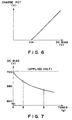
- a relation between the applied DC bias in the case of the charging type using the discharge and the charged potential of the photosensitive member(which is 0 before the charging) is as shown in Figure 6.
- the photosensitive member 1 has a charge starting voltage Vth. So, if the DC bias is not more than Vth, the magnetic brush charging device 2 can be supplied with a constant potential difference with the photosensitive member 1 being not charged.
- the charge starting voltage Vth changes with the thickness and the dielectric constant of the photosensitive layer.
- the reflection density meter 7 detects the toner to be developed for the density balance adjustment, it detects the toner on the drum discharged from the magnetic brush charging device 2, and the toner amount in the magnetic brush charging device 2 is calculated on the basis of the detected reflection density. Even if the amount of the toner discharged from the charging device is small, the toner amount in the charging device can be predicted by detecting the discharged toner amount, since there is a certain relation between the discharged toner amount and the toner amount remaining in the charging device after the discharge.
- the setting is changed to raise the DC bias of the charging bias among the process conditions so as to provide the predetermined charged potential even if the toner is introduced into the magnetic brush charging device.
- the image forming operation is prohibited when the toner amount is higher than a predetermined level.
- the charged potential can be controlled for the image forming unit for each color, so that stabilized color images can be formed for long term.
- an image forming apparatus wherein the untransferred toner is at least temporarily collected by the magnetic brush charging device, the predetermined cleaning bias is applied to the magnetic brush charging device so as to returns the toner from the charging device onto the image bearing member, and the toner density of the toner returned to the photosensitive member is measured, and on the basis of the measurement, the toner amount in the magnetic. brush is predicted, and then, the setting of the image forming process condition of the image forming apparatus is changed, or as an uncovered alternative the image forming operation is prohibited; by which the defective image due to the deterioration of the charging property as a result of the increase of the amount of introduced toner in the magnetic brush charging device can be prevented beforehand.
- a color image forming apparatus is used, but this is not limiting.
- the adjustment of the charging bias is not limiting either, and it shows an example of the process condition change.
- This embodiment is similar to the first embodiment, but uses an injection charging type.
- the toner density detection method will be described.
- the applied DC bias is substantially the same as the charged potential in the injection charging type, and therefore, the introduced toner is incapable of being discharged by a constant potential difference.
- a relation is determined beforehand between the toner density of the toner discharged by the potential difference at this time and the amount of introduced toner in the charging device. Using the relation, the same advantageous effects as the first embodiment are provided.
- an image forming apparatus using an injection charging type wherein the toner amount in the magnetic brush is predicted, using a predetermined relation, by measuring the toner density on the photosensitive member, and on the basis of the measurement, the toner amount in the magnetic brush is predicted, and then, the setting of the image forming process condition of the image forming apparatus is changed, or the image forming operation is prohibited, by which the defective image due to the deterioration of the charging property as a result of the increase of the amount of introduced toner in the magnetic brush charging device can be prevented beforehand.
- This embodiment provides an image forming apparatus wherein the untransferred toner is at least temporarily collected by a magnetic brush charging device, wherein the toner amount in the magnetic brush is predicted on the basis of image data and a transfer efficiency, and in accordance with the predicted toner amount, the setting of the image forming process condition for the image forming apparatus is changed, or as an alternative not covered by the claims the image forming operation is prohibited.
- the image forming apparatus is a copying machine or laser beam printer having a digital image processing function.
- the fundamental structure is similar to the first example not covered by the claims.
- the amount of the toner on the photosensitive member is calculated on the basis of the amount of image data (video signal) to be projected onto the photosensitive member 1 as a laser beam, and the resultant value is multiplied by a transfer efficiency at the transfer portion, by which the untransferred toner amount in the magnetic brush charging device 2 is calculated.
- Untransferred toner amount development toner amount x (1-transfer efficiency).
- the toner introduced into the charging device 2 has a particular relation with the untransferred toner amount.
- the setting of the image forming process condition of the image forming apparatus is changed, or the image forming operation is prohibited.
- the setting of the DC bias of the developing bias is lowered.
- the transfer efficiency of the image forming apparatus is stably 90-95%, and therefore, a constant transfer efficiency is used. Therefore, the transfer efficiency was not detected in this embodiment.
- a sensor or the like may be provided to measure the transfer efficiency(density) downstream of the transfer portion with respect to a rotational direction of the photosensitive member.
- the amount of introduced toner in the magnetic brush charging device 2 increases, and therefore, the charging property thereof is deteriorated with the result of so-called reverse charge fog.
- the developing bias is lowered in accordance with the deterioration of the charging property so that reverse charge fog can be prevented.
- an image forming apparatus wherein an untransferred toner is at least temporarily collected by a magnetic brush charging device, wherein the toner amount in the magnetic brush is calculated on the basis of the image data (and the transfer efficiency), and the setting of the image forming process condition of the image forming apparatus is changed in accordance with the toner amount, or as an alternative not covered by the claims the image forming operation is prohibited, by which the defective image due to the deterioration of the charging property as a result of the increase of the amount of introduced toner in the magnetic brush charging device can be prevented beforehand. Furthermore, the amount of introduced toner in the magnetic brush charging device can be measured without adding a particular means.
- the charging bias applied to the magnetic brush charging device is an oscillating voltage in the form of a DC bias(DC voltage) plus AC bias(AC voltage) superposed to each other to increase the charging property.
- This is intended to raise the charged potential at the polarity which is the same as the AC bias charging potential, and to converge the charging potential to the predetermined potential(DC bias level) by the alternating application, thus supplementing the deterioration of the charging property of the magnetic brush charging device.
- the degree of raising of the charging potential of the AC bias is determined by the level of the voltage at the same polarity as the charging potential. In order to converge the charging potential to the predetermined potential, it is preferable that level at the opposite polarity side from that of the charging potential of the AC bias is the same as that at the same polarity side. Therefore, the charging property of the magnetic brush charging device is determined by the peak-to-peak voltage (Vpp) of the AC bias.
- Vpp peak-to-peak voltage
- FIG 8 is a schematic view of an example of an image forming apparatus according to uncovered example 1.
- the image forming apparatus of this embodiment is a laser beam printer of cleaner-less type using a transfer type using a electrophotographic process and using a magnetic brush charging.
- Designated by 1 is an electrophotographic photosensitive member of a rotatable drum type as an image bearing member.
- the photosensitive member 1 is rotated in the clockwise direction indicated by the arrow at a predetermined process speed (peripheral speed).
- Designated by 2 is a magnetic brush charging device as a contact charging device contacted to the photosensitive member 1. It is in the form of a rotatable sleeve.
- the magnetic brush charging device 2 will be described hereinafter.
- the magnetic brush charging device 2 is supplied with an oscillating voltage having a periodically changing voltage level (DC plus AC) from a charging bias applying voltage source S1 to uniformly charge the outer peripheral surface of the photosensitive member 1 to a predetermined polarity and potential.
- the DC bias component has a level equivalent to the desired charged potential, and is -700V (Vdc).
- the charged surface of the photosensitive member 1 is exposed to scanning exposure L by a laser scanner 7, so that electrostatic latent image is formed on the peripheral surface of the rotatable photosensitive member 1 in accordance with the intended image information.
- the laser scanner 7 emits a laser beam modulated in intensity corresponding to time series digital pixel signal of intended image information.
- Designated by 7a is a deflection mirror to direct the output laser beam from the laser scanner 7 to the photosensitive member 1.
- the electrostatic latent image on the surface of the photosensitive member 1 is developed (reverse development) into a toner image by a developing device 3 using insulative toner.
- Designated by S2 is a developing bias applying voltage source for applying a predetermined developing bias to the developing device 3.
- a transfer material P as a recording material is fed out to an unshown sheet feeding station and is fed into a nip (transfer portion)T formed between the photosensitive member 1 and a transfer roller 4 as a contact type transferring device having an intermediate resistance contacted thereto a predetermined urging force.
- the transfer roller 4 is supplied with a transfer bias voltage of the polarity opposite from that of the toner from the transfer bias application voltage source S3.
- the transfer material P introduced to the transfer portion T is passed through the nip, and the toner image is continuously transferred from the surface of the photosensitive member 1 onto the transfer material P by the electrostatic force and the pressure.
- the transfer material P now having the toner image, is separated from the surface of the photosensitive member 1, and is fed to a heat fixing type fixing device 5, where the toner image is fixed on the transfer material P. Finally, it is discharged as a print.
- No cleaning device exclusively for the removal of the untransferred toner from the surface of the photosensitive member after the toner image transfer is provided.
- the surface of the photosensitive member after the toner image transfer to the transfer material P reaches the contact portion n where it is contacted to the magnetic brush charging device 2, while carrying the untransferred toner.
- the untransferred toner is at least temporarily taken up by sliding force and the charging bias(negative) of the magnetic brush, so that surface is cleaned (simultaneous charging and cleaning) to be, used again for the image formation.
- the untransferred toner introduced into the magnetic brush charging device 2 is charged by the friction with the magnetic particles 23, and is discharged uniformly onto the surface of the photosensitive member, and is then collected (simultaneous development and cleaning) by the developing device 3 at a developing station to be reused for the development.
- Figure 9 is a view of a magnetic brush charging device 2. It comprises a magnet roller 2b as magnetic field generating means, a non-magnetic electrode sleeve 2a of aluminum or the like enclosing the magnet roller coaxially and rotatably, a magnetic brush layer 2d of magnetic particles 2c magnetically attracted on the outer peripheral surface of the electrode sleeve by the magnetic force of the magnet roller 2b therein, and a detecting device 25, deposited adjacent to the magnetic brush layer, for detecting a toner amount in the magnetic brush layer.
- the magnetic particles 2c constituting the magnetic brush portion 2d may be of magnetic metal particles such as ferrite or magnetite particles, or these particles bound by binder region.
- the resistance value is preferably 1x 10 5 -10 8 ⁇ cm.
- the particle size thereof is preferably 10-50 ⁇ m. It is preferable to mix a plurality of magnetic particles, since the charging property may be improved.
- the resistance value of the magnetic particles is measured in the following manner: 2g of the magnetic particles is placed in a metal cell having a bottom surface area of 228mm 2 to which a voltage is applicable, and the current is measured when a voltage of 100V is applied. This is used in embodiments 1-4, too.
- the average particle size of the magnetic particles is indicated by a maximum angular distance in the horizontal direction. More than 300 particles are randomly extracted using an optical microscope, and diameters thereof are measured, and the measurements are averaged.
- a DC magnetization B-H property automatic recording device BH-50 available from Riken Denshi Kabushiki Kaisha, is usable.
- the particles are filled into a cylindrical container having a diameter(inner diameter)6.5mm and height 10mm, at approx. 2g, and motion of the particles in the container is prevented.
- the saturation magnetization is measured from the B-H curve.
- the magnetic brush charging device 2 is disposed substantially in parallel with the photosensitive member 1 with a space of 0.5mm between the surface of the electrode sleeve 2a and the surface of the photosensitive member 1. The space is maintained by a spacer member (unshown) contacted to the photosensitive member at the longitudinal ends.
- the magnetic brush layer 2d is formed with a predetermined width (charge portion n) relative to the surface and is contacted to the surface of the photosensitive member 1.
- the direction of movement of the surface of the electrode sleeve 2a is opposite from that of the photosensitive member 1, and is rotated in the clockwise direction indicated by the arrow in the Figure. They may be rotated at the same peripheral speeds, and the magnetic brush layer 2d is rotated in the same direction as the sleeve, so that surface of the photosensitive members 1 rubbed by the magnetic brush layer 2d.
- the electrode sleeve 2a of the magnetic brush charging device 2 is supplied from the charging bias applying voltage source S1 with the predetermined charging bias Vdc+Vac (oscillating voltage), so that photosensitive member surface is charged substantially to the same potential as the DC bias component Vdc of the applied charging bias by the charge portion n through the magnetic particles 2c of the magnetic brush layer 2d.
- Vdc+Vac oscillating voltage
- the untransferred toner on the surface on the photosensitive member after the toner image transfer reaches, by the rotation of the photosensitive member 1, the portion of the magnetic brush charging device 2, and is at least temporarily collected in the magnetic brush layer 2d (simultaneous charging and cleaning).
- the charging property of the magnetic brush charging device 2 is deteriorated due to the introduction of the toner which has the high resistance into the magnetic brush layer 2d.
- a detecting device 25 for detecting the toner amount in the magnetic brush charging device 2 (magnetic brush layer 2d).
- the detected information is fed to the control circuit portion(CPU) 26.
- the control circuit portion 26 controls the charging bias applying voltage source S1 in accordance with the detected toner amount to change AC bias component Vac of the charging bias Vdc+Vac between a first bias value V1 (reference) and a second bias value V2 having a peak-to-peak voltage larger than that of the first bias value V1.
- the toner amount in the magnetic brush charging device is changed to provide a stabilized charging property and to prevent the deposition of the magnetic particles to the photosensitive member.
- the toner amount detecting device 25 may be any if it can detect the toner amount in the magnetic brush layer 2d.
- a photo-sensor used in a two-component developer type developing device is available, which detects the reflected light quantity.
- the AC bias component(peak-to-peak) of the charging bias Vdc+Vac applied to the magnetic brush charging device 2 is made large in consideration of the possibility that charging property thereof will be deteriorated by the introduction of the untransferred toner into the magnetic brush layer, a large potential difference occurs in magnetic particles at the initial stage of use of the magnetic brush charging device in which the amount of the untransferred toner is small. This may make the magnetic particle deposition on the photosensitive member 1.
- the first AC bias V1 having a peak-to-peak voltage which is smaller than a reference voltage
- the second AC bias V2 having a peak-to-peak voltage which is larger than the reference voltage is applied to the charging bias.
- the AC bias is made smaller to prevent the deposition of the magnetic particles to the photosensitive member, and when the toner amount is large, the AC bias is made larger to improve the charging property.
- the toner amount When the toner amount is large, the magnetic particle deposition does not occur, since even if the AC bias is made larger, the toner is deposited onto the photosensitive member since the toner has a higher resistance value than the magnetic particle.
- the level of the AC bias component of the charging bias applied to the magnetic brush charging device 2 in accordance with the toner amount in the magnetic brush charging device detected by the toner amount detecting device 25, is controlled among three levels, namely, a first bias value V1 (reference), a second bias value V2 having a larger peak-to-peak voltage larger than that of the first bias value V1, and a third bias value V3 having a smaller peak-to-peak voltage larger than that.
- the apparatus of this embodiment is the same as that of the third embodiment in the other respects.
- control flow of Figure 10 in third embodiment is modified to apply the AC bias V3 having a peak-to-peak voltage smaller than V 2 .
- the AC bias is made smaller than the reference value, the deposition of the magnetic particles can be reduced further, when the amount of introduced toner is very small, such as immediately after the cleaning bias is applied to returns the introduced toner to the photosensitive member.
- the AC bias component of the charging bias applied to the magnetic brush charging device 2 in accordance with the toner amount in the magnetic brush charging device detected by the toner amount detecting device 25 is continuously changed.
- the apparatus of this embodiment is the same as that of the third embodiment in the other respects.
- the AC bias is stepwisely changed in accordance with the amount of introduced toner.
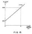
- the AC bias is continuously changed in accordance with the toner amount in the magnetic brush charging device, as shown the flow chart of Figure 12.
- the AC bias can correspond precisely to the toner amount in the magnetic brush charging device, so that charging property of the magnetic brush charging device is stabilized, and therefore, good images can be provided for a long term.
- the AC bias V is controlled in accordance with the toner amount x detected by the toner amount detecting device 25. It was confirmed that good images were provided for a long term.
- the relation may be determined by a non-linear line.
- the relation between the toner amount in the magnetic brush charging device and the charged potential is determined beforehand on the basis of measurements, and the relational expression may be determined on such a relation. By doing so, further stabilization of the charging property is accomplished.
- the charging property of the magnetic brush charging device may be deteriorated by introduction of the high resistance untransferred toner into the magnetic brush portion of the magnetic brush charger.
- the toner introduced and accumulated in the magnetic brush portion is discharged to limit the accumulation amount below an allowable level, thus maintaining the charging property. This may be accomplished by changing the bias setting or the operation state of the magnetic brush charger(magnetic brush cleaning mode).
- the electroconductive magnetic particles constituting the magnetic brush portion of the magnetic brush charger preferably have the resistance value of 1x 10 5 -1x 10 8 ⁇ cm from the standpoint of assuring the charging property and of preventing leakage when the photosensitive member as the member to be charged has a pin hole.
- the toner has a resistance value of not less than 1x 10 15 ⁇ cm (high resistance). Therefore, the charge retentivity of the toner is higher than the magnetic particle.
- the magnetic particles as well as the toner may be transferred to the photosensitive member when the toner amount in the magnetic brush portion is small.
- both of the maintenance of the charging property by discharging the toner to the photosensitive member and the reduction of the deposition of the magnetic particles to the photosensitive member, are accomplished.
- the image forming apparatus used in this embodiment is the same as that of third embodiment ( Figure 8), and the fundamental structure of the magnetic brush charging device is the same as the third embodiment ( Figure 9). Therefore, the detailed description thereof is omitted for simplicity.
- the magnetic particles 2c constituting the magnetic brush layer 2d may be of ferrite, magnetite or another magnetic metal particles, or may be such particles bound by binder resin.
- the average particle size thereof is preferably 10-100 ⁇ m, and the saturation magnetization at 1000 Gauss is preferably 20-300emu/cm 3 , and the resistance is preferably 10 5 -10 8 ⁇ cm.
- ferrite particles having the average particle size of 30 ⁇ m, the volume resistivity of 6x 10 7 ⁇ cm, the saturation magnetization at 1000 Gauss of 280emu/cm 3 , and the specific gravity of 5.2g/cm 3 were used.
- the average particle size, the resistance and the magnetic property of the magnetic particles is measured in the same manner as in the third embodiment.
- a device 25 for detecting the toner amount introduced into the magnetic brush portion 2d as shown in Figure 9.
- the cleaning mode is executed or not.
- the toner amount detecting device 25 may be any if it can detect the toner amount in the magnetic brush portion 2d.
- a photo-sensor used in a two component developing device is usable which detects the reflected light quantity; or a resistance change of the magnetic brush portion is predicted on the basis of detection of the charging current through the charger.
- the toner amount detecting means or method does not limit the present invention.
- the output of the toner amount detecting device 25 is fed to a control circuit.
- the control circuit 26 controls the charging bias applying voltage source S1 in accordance with the input detected information to switch the enablement of the cleaning mode operation.
- the toner discharge cleaning mode for the magnetic brush portion 2d is carried out fundamentally as shown in a timing chart of Figure 14, not when the charging is carried out for the image formation for the hatched portion. More particularly, it is carried out between charging operation for a certain image formation and charging operation for the next image formation(between recording sheets), before the charging for the initial image formation or after the charging for the final image formation.
- the discharge of the toner to the photosensitive member from the magnetic brush portion 2d is effected by the potential difference between the DC bias component applied thereto and the charged potential of the photosensitive member 1, when the AC bias component of the charging bias applied to the magnetic brush charging device 2 is rendered off.
- the charged potential on the photosensitive member 1 was -400V.
- the control circuit 26 controls the voltage source S1 to execute the cleaning mode to positively discharge the toner from the magnetic brush portion 2d. If, on the other hand, the detected toner amount is less than the predetermined regulation value, the control circuit 26 controls the voltage source S1 not to execute (to skip) the cleaning mode.
- the cleaning mode operation is carried out to maintain the charging property, and when the toner amount is small, the cleaning mode is not carried out to prevent the deposition of the magnetic particles onto the photosensitive member.
- the cleaning mode is carried out when the toner amount is not less than0.03wt%. It was confirmed that stabilized charging property and carrier deposition prevention were both accomplished even when the toner amount in the magnetic brush portion 2d varied.
- the operation period of the cleaning mode when the image forming operation is not carried out is changed in accordance with the toner amount in the magnetic brush portion 2d detected by the detecting device 25, and when the toner amount in the magnetic brush portion 2d is not less than a predetermined regulation value, a cleaning mode A having long operation period is carried out to positively discharge the toner from the magnetic brush portion 2d to maintain the deterioration of the charging property.
- a cleaning mode B having a short operation period is carried out to prevent the deposition of the magnetic particles from the magnetic brush portion 2d to the drum.
- the stabilized charging property can be maintained while preventing the deposition of the magnetic particles.
- the operation period t 0, and when the toner amount is not less than0.05wt%, the operation period is the maximum, and the operation period is changed linearly therebetween in accordance with the toner amount detected. It was confirmed that by this, the stabilized charging property was provided while preventing the magnetic particle deposit.
- a device 25 for detecting the toner amount introduced into the magnetic brush portion 2d and in accordance with the toner amount detected by the detecting device 25, a cleaning intensity of the cleaning mode for the magnetic brush portion is switched by changing the potential difference for discharging the toner from the magnetic brush portion during the cleaning mode.
- the operation period in the cleaning mode in this example is similar to that shown in the timing chart of Figure 14 in the sixth embodiment. It is an alternative to change the operation period in accordance with the toner amount in the magnetic brush portion 2d, as in the seventh embodiment.
- high intensity cleaning mode operation is carried out when the toner amount in the magnetic brush portion is not less than a regulation'value to maintain the charging property, and when the toner amount is less than the regulation value, the low intensity cleaning mode operation is carried out to reduce the magnetic particle deposit.
- the potential difference relative to the photosensitive member 1 is 50V, and when the toner amount is 0.05wt%, the potential difference is changed to 300V.
- the method of detecting a physical quantity relating to the toner amount in the charging device as shown in embodiments 1-2 and uncovered examples 1-2 may be used.
- image bearing member is provided with a surface charge injection layer(injection charging type) similarly to uncovered example 1.
Landscapes
- Physics & Mathematics (AREA)
- General Physics & Mathematics (AREA)
- Engineering & Computer Science (AREA)
- Plasma & Fusion (AREA)
- Electrostatic Charge, Transfer And Separation In Electrography (AREA)
- Control Or Security For Electrophotography (AREA)
Description
- The present invention relates to an image forming apparatus provided with a charging device the contactable to an image bearing member to charge the image bearing member.
- An electrophotographic apparatus is known wherein an image bearing member such as a photosensitive member is charged by a magnetic brush contact charging device. The contact charging device has an advantage that amount of the ozone product is smaller than a corona discharger.
- However, the contact charging involves a problem that if the toner particles are introduced into the magnetic brush, the charging property of the charging device is deteriorated, since the magnetic particles forming the magnetic brush are electroconductive, whereas the toner particles of the toner image formed on the image bearing member are insulative.
- Particularly, when the cleaning for removing residual toner from the photosensitive member after image transfer is not used for purpose of downsizing of the image forming apparatus, and such toner is removed by the developing device, then amount of the introduced toner is large since a large amount of the toner reaches the charging position of the charging device. In the case that residual toner is temporarily collected from the photosensitive member by the charging device, the toner mixing amount is further large with the result of remarkable deterioration of the charging property. The amount of introduced toner varies depending on image forming conditions, and the charging property is different depending on the amount of introduced toner.
- In an injection charging type wherein the charge is directly injected-into the photosensitive member, a contact charging device directly injects the charge into the charge injection layer provided at the photosensitive member surface. Therefore, the deterioration of the charging property resulting from the toner introduction is more significant than in the normal charging type using electric discharge.
- The deterioration of the charging property results in image defect in the resultant image.
- Document EP-A-0 622 703 discloses an image forming apparatus using a contact-type charger to charge a photoreceptor. Document JP 06-266266 A discloses an image forming apparatus comprising a cleaning member in the vicinity of the magnetic brush to collect toner therefrom. Document JP 06-230654 A discloses to detect electrostatic charging performance of a magnetic brush charging means by detecting a current.
- Accordingly, it is a principal object of the present invention to provide an image forming apparatus wherein deterioration of the charging property due to introduction of the toner into the charging device is prevented.
- It is another object of the present invention to provide an image forming apparatus wherein the image defect due to introduction of the toner into the charging device is prevented.
- These objects are achieved by an image forming apparatus according to claim 1.
- Advantageous further developments of the present invention are as set out in the dependent claims.
- These and other objects, features and advantages of the present invention will become more apparent upon a consideration of the following description of the preferred embodiments of the present invention taken in conjunction with the accompanying drawings.
- Figure 1 is a schematic illustration of an image forming apparatus according to an example not covered by the claims.
- Figure 2 is a graph showing a photosensitive member potential obtained by charging current measurement in a first example not covered by the claims.
- Figure 3 is a graph of a relation between the toner amount in the magnetic brush charging device and the current in the first example not covered by the claims.
- Figure 4 is a graph showing a relation between an applied voltage and a surface potential of the photosensitive member in an injection charging type.
- Figure 5 is a schematic illustration of an example of color image forming apparatus according to an embodiment of the present invention.
- Figure 6 is a graph showing a charging DC bias and a charged potential according to a first embodiment.
- Figure 7 is a graph showing a relation between an amount of introduced toner in the magnetic brush charging device and a charged potential in an injection charging type.
- Figure 8 is a schematic illustration of an image forming apparatus according to a third embodiment.
- Figure 9 is a schematic view of a magnetic brush charging device of a rotatable sleeve type.
- Figure 10 is a flow chart for an AC bias control used in the third embodiment.
- Figure 11 is a flow chart for an AC bias control used in the third embodiment.
- Figure 12 is a flow chart for an AC bias control used in a fifth embodiment.
- Figure 13 is a graph of an example of a relation between a toner amount in a magnetic brush charging device and an AC bias in the fifth embodiment.
- Figure 14 is a timing chart in a cleaning mode.
- Figure 15 is a flow chart for determining setting in a cleaning mode.
- Figure 16 is a timing chart of a cleaning mode used in an apparatus according to a seventh embodiment.
- Figure 17 shows a relation between a charging AC bias and a charged potential of the photosensitive member.
- Figure 18 shows a relation between a charging AC bias and a charged potential of the photosensitive member.
- Referring to the accompanying drawings, the embodiments of the present invention will be described.
- This example relates to an image forming apparatus wherein an untransferred toner is at least temporarily collected in a magnetic brush charging device, and a toner amount in the magnetic brush is predicted or estimated on the basis of a current through the magnetic brush charging device, and the setting of the image forming process condition of the image forming apparatus is changed.
- Figure 1 is a schematic illustration of an image forming apparatus according to an example not covered by the claims. The image forming apparatus in this example is a laser beam printer using an electrophotographic process.
- Designated by 1 is an electrophotographic photosensitive member of a rotatable drum type as an image bearing member. The photosensitive member 1 is rotated in the clockwise direction indicated by the arrow. The photosensitive drum 1 comprises an electroconductive base of metal or the like which is electrically grounded, and a photosensitive layer.
- In this example, the photosensitive layer is an organic photoconductive layer having a negative charging polarity.
- Designated by 2 is a contact charging device using a magnetic brush contacted to the photosensitive member 1, and it comprises a rotatable
non-magnetic electrode sleeve 21, amagnet 22, and an electroconductivemagnetic particles 23 deposited on the sleeve by the magnetic force of themagnet 22. Thesleeve 21 for themagnetic brush 2 is supplied with a charging bias voltage comprising a DC bias(negative polarity) and an AC bias superposed thereon from a charging bias applying voltage source S1 to uniformly charge the outer peripheral surface of the photosensitive member 1. Between the magnetic brush charging device and the charging bias electrode S1, a detectingdevice 24 for detecting a current through the magnetic brush, is provided, and a process condition for image formation is changed in accordance with the current detected thereby. The volume resistivity of themagnetic particle 23 is preferably 1x 10⁵-1x 10⁸Ωcm. - The charged surface of the photosensitive member 1 is exposed to scanning exposure L emitted from a laser beam modulated in the intensity, corresponding to the pixel signal, so that electrostatic latent image is formed on the peripheral surface of the rotatable photosensitive member 1 in accordance with the intended image information. The electrostatic latent image is developed into a toner image with an insulative toner(negative charging polarity) by a developing bias applied from the developing bias applying voltage source S2.
- The volume resistivity of the toner is preferably not less than 1x 10¹⁵Ωcm.
- On the other hand, a transfer material P as a recording material is supplied from an unshown sheet feeding station, and is introduced at a predetermined. timing into a nip(transfer portion)T formed between the photosensitive member 1 and a transfer roller 4 as a contact type transferring means which is contacted thereto at a predetermined pressure and which has an intermediate resistance. To the transfer roller 4, a transfer bias voltage(positive polarity) of the polarity opposite from that of the toner is applied from a transfer bias application voltage source S3, so that charge of the polarity opposite from that of the toner charge is applied to the back side of the transfer material.
- The transfer material P introduced to the transfer portion T is passed through the nip, and the toner image is continuously transferred from the surface of the photosensitive member 1 onto the transfer material P by the electrostatic force and the pressure. The residual toner remaining on the photosensitive member after the image transfer is partly charged to the positive polarity by the transfer charging.
- The transfer material P now having the toner image, is separated from the surface of the photosensitive member 1, and is fed to a heat fixing
type fixing device 5, where the toner image is fixed on the transfer material P. Finally, it is discharged as a print. - The surface of the photosensitive member after-the toner image transfer to the transfer material P, reaches the position where it is contacted to the magnetic
brush charging device 2, while carrying the untransferred toner. By the magneticbrush charging device 2, the untransferred toner is partly taken up by sliding force and the charging bias(negative) of the magnetic brush, so that surface is cleaned to be used again for the image formation. Among the residual toner after the transfer, those charged to the negative polarity, passes through the contact portion, but those charged to the positive polarity is attracted into the magnetic brush. The photosensitive member region having the untransferred toner is charged by the charging device, and then, is exposed to an image so that latent image is formed. - The untransferred toner introduced into the magnetic
brush charging device 2, is charged by the friction with themagnetic particles 23 to the negative polarity which is the normal charging polarity, and is discharged uniformly onto the surface of the photosensitive member, and is then collected by the developingdevice 3 at a developing station to be reused for the development. The developing bias of the developing device is so selected that negative residual toner is removed, while the normal is effected. More particularly, it is selected to be between the dark portion potential and the light portion potential, by which an electric field is formed in such a direction that toner is deposited from the developing sleeve to the light potential portion, whereas the toner returns from the dark potential portion to the developing sleeve. The polarity of the untransferred toner is uniformed to the normal negative polarity by the chargingdevice 2, so that pattern of the untransferred toner is removed, thus preventing production of the remaining image. - The description will be made as to a device for detecting a physical quantity relating to the toner amount to predict the toner amount in the magnetic brush charging device used in this example.
- The magnetic brush charger of this example comprises, as shown in Figure 1, a rotatable
non-magnetic electrode sleeve 21, amagnet 22, andmagnetic particles 23 deposited by the magnetic force on the sleeve. - The magnetic
brush charging device 2 is supplied with the charging bias in the form of the DC voltage biased with the AC bias voltage from the charging bias applying voltage source S1, and the detectingdevice 24 is provided between the magneticbrush charging device 2 and the charging bias voltage source S1 to detect the DC current through the magnetic brush. - In order to detect the resistance of the magnetic brush correctly, the potential difference between the magnetic brush and the photosensitive member 1 is made constant. During the image formation, the potential difference from the photosensitive member is not constant because of the change of the image ratio and/or the transfer voltage. Therefore, the current detection is not carried out during the image forming operation, and is carried out when the image is not formed, with the potential of the photosensitive member being kept constant. In this example, the photosensitive member is subjected to a whole surface exposure to uniform laser beam L when the image forming operation is not carried out, and the developing bias applying voltage source S2 and the transfer bias application voltage source S3 are rendered off, and a predetermined voltage Vdc is applied to the
sleeve 21, while the light portion potential of the photosensitive member is V1. The DC current supplied to thesleeve 21 is then measured. - The measured current(a physical quantity relating to the toner amount) is compared with a relation, as shown in Figure 3, between the toner amount in the magnetic brush charging device and the current, which relation has been measured beforehand. And, the toner amount in the magnetic
brush charging device 2 is determined therein as the toner amount for the measured potential difference(Vdc-V1). - In accordance with the toner amount thus determined, a
processing device 6 determines image forming process conditions such as the charging bias and developing bias, and changes the process conditions accordingly. In this example, when the amount of the toner is in the magneticbrush charging device 2, the image forming operation of the main assembly is prohibited, and a warning signal is produced to a user. - When the number of prints increases, the amount of introduced toner in the magnetic
brush charging device 2 increases, and if the voltage applied to the electrode sleeve is constant, the improper charging occurs with the result of defective image formed. This problem is overcome in this embodiment, since the main assembly operation is stopped if the charging property is deteriorated. - In this example, the charging bias is in the form of an AC biased DC voltage, and the discharging thereby is used. However, the present invention is not limited to a particular charging type, and is applicable to a magnetic brush charging device of any injection charging type wherein the charge is directly injected into a charge injection layer of a photosensitive member.
- In the injection charging type, the charge injection is directly effected by a contact charging member having an intermediate resistance into the photosensitive member surface not through discharge phenomenon. Therefore, the photosensitive member is charged to a potential corresponding to the applied voltage to the charging member, even if the applied voltage is lower than the discharge threshold. A relation between the applied voltage and the surface potential of the photosensitive member is shown in Figure 4 (when the toner is not introduced into the charger).
- The charge injection layer in this example is produced as follows. SnO2 particles having a particle size of approx. 0.03µm made electroconductive by antimony-doping, are dispersed in photo-curing type acrylic resin material at 5:2 parts by weight, and 3 parts by weight of Teflon particles having a particle size of 0.5µm are added thereto. The material thus produced is applied on the OPC photosensitive layer through dip coating method. The thickness thereof is 3µm.
- If the resistance value is too low, the image is blurred due to lateral flow of the latent image charge along the surface, and if it is too high, the charge injection into the charge injection layer is difficult. The volume resistivity of the charge injection layer is preferably in the range of 1x 10¹⁰-1x 10¹⁴Ωcm, and is further preferably 1x 10¹²-1x 10¹³Ωcm under the normal temperature and normal humidity condition (23.5°C, 60%), if the resistance change under high temperature and high humidity and low temperature low humidity conditions are taken into account.
- The volume resistivity of the charge injection layer is measured, using a sample thereof in the form of a sheet and a HIGH RESISTANCE METER 4329A (available from Yokogawa Hewlett-Packard Kabushiki Kaisha, Japan) connected to a RESISTIVITY CELL 16008A, with a voltage of 100V applied.
- The control of this example can be used with such an injection charging type image forming apparatus by measuring the DC current through the magnetic brush charging device.
- As described in the foregoing, according to this example, there is provided an image forming apparatus wherein the untransferred toner is at least temporarily collected by the magnetic brush charging device, the toner amount in the magnetic brush is predicted on the basis of the current through the magnetic brush charging device, and in accordance with the predicted toner amount, the image forming process condition of the image forming apparatus is changed, or the image forming operation is prohibited, so that production of defective image due to the deterioration of the charging performance can be prevented beforehand.
- This example provides an image forming apparatus wherein the untransferred toner is at least temporarily collected by a magnetic brush charging device, wherein a cleaning bias is applied to the magnetic brush charging device so as to return a part of toner from the charging device to the photosensitive member, and a toner content on the photosensitive member at this time(a physical quantity relating to the amount of introduced toner) is measured. The toner amount in the magnetic brush is predicted on the basis of the measurement, and the process condition of the image forming apparatus is set in accordance with the prediction. As a further alternative, but not covered by the claims, the image forming operation is prohibited.
- Figure 5 is a schematic illustration of an image forming apparatus according to an embodiment of the present invention. In this example, the image forming apparatus is a color image forming apparatus using an electrophotographic process.
- The color image forming apparatus of this example is provided with a plurality of photosensitive members for the purpose of high speed color image output, wherein a transfer material is fed by a feeding means in the form of a belt, and the toner images are sequentially transferred superimposedly on the transfer material. An image forming unit is constituted by a photosensitive member, the magnetic brush charging device, an image exposure device and a developing device, and the untransferred toner is at least temporarily collected by the magnetic brush charging device. The structures are quite similar to those of the first example not covered by the claims.
- The image forming unit forms color images using 4 units for magenta toner(UM), cyan toner (UC), yellow toner(UY), and black toner(UBk).
- In the image forming unit for (magenta)UM, a photosensitive member 1M is rotated in the clockwise direction indicated by an arrow, and the outer peripheral surface of the photosensitive member 1M is uniformly charged by a magnetic
brush charging device 2M contacted to the surface. - The surface of the photosensitive member 1M thus charged is exposed to laser beam LM modulated in accordance with a pixel signal for the magenta color provided by color separation of a color image, so that electrostatic latent image is formed on the peripheral surface of the photosensitive member 1M, corresponding to the image information for the magenta color. The electrostatic latent image is developed into a magenta toner image by a developing
device 3M containing insulative magenta toner. - The similar process is carried out in each of the units for cyan UC, yellow unit UY, black unit UBk, so that toner images are formed, corresponding to the image information for each color.
- On the other hand, a transfer material P as a recording material is supplied from an unshown sheet feeding station, and is carried on a
transfer belt 41. The toner images are sequentially transferred superimposedly on the transfer material P bytransfer blades 42 sandwiching thetransfer belt 41 with the photosensitive member 1. - The transfer material P now having the toner image, is separated from the surface of the photosensitive member 1, and is fed to a heat fixing
type fixing device 5, where the toner image is fixed on the transfer material P. Finally, it is discharged as a print. - The surface of each of the photosensitive members after the toner image transfer to the transfer material P, reaches the position where it is contacted to the magnetic
brush charging device 2, while carrying the untransferred toner. By the magneticbrush charging device 2, the untransferred toner is partly taken up by sliding force and the charging bias(negative) of the magnetic brush, so that surface is cleaned to be used again for the image formation. - The untransferred toner taken in the magnetic
brush charging device 2 has a normal charging polarity as a result of friction with themagnetic particles 23. The toner (negative) is discharged uniformly to the surface of the photosensitive member, and similarly to the first uncovered example, the photosensitive member surface carrying the remaining toner is uniformly charged and exposed to image light, and is then subjected to a developing operation at the developing station by a developingdevice 3, and simultaneously therewith, the residual toner is collected by the developing device and is reused. - The description will be made as to a device for detecting a physical quantity relating to the toner amount to predict the toner amount in the magnetic brush charging device used in this example.
- The color image forming apparatus of this example is provided with a
reflection density meter 7 for measuring a toner density on the photosensitive member to keep the color balance. - The
reflection density meter 7 measures the toner density of the developed image in the non-sheet-passing area(non-image area) on the photosensitive member after the development and before the transfer, and in accordance with the measurement, the bias is adjusted to adjust the color balance. - In this example, the
reflection density meter 7 is utilized. When the image is not formed, a constant potential difference is provided to the magneticbrush charging device 2, and at this time, a part of the toner in the charging device is discharged from the charging device onto the photosensitive member 1. The toner density of the discharged toner (a physical quantity relating to the amount of introduced toner) is measured, on the basis of which the toner amount in the magneticbrush charging device 2 is predicted. - Actually, when the image is not formed, the photosensitive member is subjected to whole surface exposure by the laser beam L, and the developing bias and the transfer bias are rendered off to provide a uniform potential. The AC bias component of the charging bias is stopped, and a DC bias of -100V is applied, by which the potential difference between the surface potential of the photosensitive member and the potential(-100V) on the magnetic brush charging device is made constant. Here, when the charging bias having only the DC bias is applied to the magnetic
brush charging device 2, a relation between the applied DC bias in the case of the charging type using the discharge and the charged potential of the photosensitive member(which is 0 before the charging) is as shown in Figure 6. The photosensitive member 1 has a charge starting voltage Vth. So, if the DC bias is not more than Vth, the magneticbrush charging device 2 can be supplied with a constant potential difference with the photosensitive member 1 being not charged. The charge starting voltage Vth changes with the thickness and the dielectric constant of the photosensitive layer. - By the constant potential difference between the photosensitive member and the magnetic
brush charging device 2, a part of the toner in the magnetic brush charging device is deposited onto the photosensitive member 1. By stopping the sleeve driving in the developingdevice 3, it reaches thereflection density meter 7 without being collected by the developingdevice 3. - Similarly to the normal operation wherein the
reflection density meter 7 detects the toner to be developed for the density balance adjustment, it detects the toner on the drum discharged from the magneticbrush charging device 2, and the toner amount in the magneticbrush charging device 2 is calculated on the basis of the detected reflection density. Even if the amount of the toner discharged from the charging device is small, the toner amount in the charging device can be predicted by detecting the discharged toner amount, since there is a certain relation between the discharged toner amount and the toner amount remaining in the charging device after the discharge. - In accordance with the increase of the toner amount, the setting is changed to raise the DC bias of the charging bias among the process conditions so as to provide the predetermined charged potential even if the toner is introduced into the magnetic brush charging device. Or, as an alternative not covered by the claims, the image forming operation is prohibited when the toner amount is higher than a predetermined level.
- Heretofore, with increase of the number of the prints, the amount of introduced toner in the magnetic
brush charging device 2 increases, and therefore, the charging property thereof is deteriorated with the result of so-called reverse charge fog caused by deposition of the toner charged to the polarity opposite from the normal polarity. According to this embodiment, the charged potential can be controlled for the image forming unit for each color, so that stabilized color images can be formed for long term. - According to this embodiment, there is provided an image forming apparatus wherein the untransferred toner is at least temporarily collected by the magnetic brush charging device, the predetermined cleaning bias is applied to the magnetic brush charging device so as to returns the toner from the charging device onto the image bearing member, and the toner density of the toner returned to the photosensitive member is measured, and on the basis of the measurement, the toner amount in the magnetic. brush is predicted, and then, the setting of the image forming process condition of the image forming apparatus is changed, or as an uncovered alternative the image forming operation is prohibited; by which the defective image due to the deterioration of the charging property as a result of the increase of the amount of introduced toner in the magnetic brush charging device can be prevented beforehand.
- In this example which is not covered by the claims, a color image forming apparatus is used, but this is not limiting. The adjustment of the charging bias is not limiting either, and it shows an example of the process condition change.
- This embodiment is similar to the first embodiment, but uses an injection charging type. The toner density detection method will be described.
- As described above, the applied DC bias is substantially the same as the charged potential in the injection charging type, and therefore, the introduced toner is incapable of being discharged by a constant potential difference.
- As shown in Figure 7, in accordance with introduction of the toner in the magnetic brush charging device, the charging property is deteriorated so that charged potential lowers. This produced a potential difference between the photosensitive member 1 and the magnetic
brush charging device 2. - A relation is determined beforehand between the toner density of the toner discharged by the potential difference at this time and the amount of introduced toner in the charging device. Using the relation, the same advantageous effects as the first embodiment are provided.
- As described above, according to this uncovered example, there is provided an image forming apparatus using an injection charging type, wherein the toner amount in the magnetic brush is predicted, using a predetermined relation, by measuring the toner density on the photosensitive member, and on the basis of the measurement, the toner amount in the magnetic brush is predicted, and then, the setting of the image forming process condition of the image forming apparatus is changed, or the image forming operation is prohibited, by which the defective image due to the deterioration of the charging property as a result of the increase of the amount of introduced toner in the magnetic brush charging device can be prevented beforehand.
- This embodiment provides an image forming apparatus wherein the untransferred toner is at least temporarily collected by a magnetic brush charging device, wherein the toner amount in the magnetic brush is predicted on the basis of image data and a transfer efficiency, and in accordance with the predicted toner amount, the setting of the image forming process condition for the image forming apparatus is changed, or as an alternative not covered by the claims the image forming operation is prohibited.
- In this example, the image forming apparatus is a copying machine or laser beam printer having a digital image processing function. The fundamental structure is similar to the first example not covered by the claims.
- The amount of the toner on the photosensitive member is calculated on the basis of the amount of image data (video signal) to be projected onto the photosensitive member 1 as a laser beam, and the resultant value is multiplied by a transfer efficiency at the transfer portion, by which the untransferred toner amount in the magnetic
brush charging device 2 is calculated. - Untransferred toner amount= development toner amount x (1-transfer efficiency).
- The toner introduced into the
charging device 2 has a particular relation with the untransferred toner amount. - In accordance with the amount of introduced toner in the magnetic
brush charging device 2 thus calculated, the setting of the image forming process condition of the image forming apparatus, is changed, or the image forming operation is prohibited. In this example, in order to prevent reverse charge fog resulting from deterioration of the charging property, the setting of the DC bias of the developing bias is lowered. - Actually, the transfer efficiency of the image forming apparatus is stably 90-95%, and therefore, a constant transfer efficiency is used. Therefore, the transfer efficiency was not detected in this embodiment. In order to make the calculation more accurate, a sensor or the like may be provided to measure the transfer efficiency(density) downstream of the transfer portion with respect to a rotational direction of the photosensitive member.
- Heretofore, with increase of the number of the prints, the amount of introduced toner in the magnetic
brush charging device 2 increases, and therefore, the charging property thereof is deteriorated with the result of so-called reverse charge fog. According to this embodiment, the developing bias is lowered in accordance with the deterioration of the charging property so that reverse charge fog can be prevented. - According to this embodiment, there is provided an image forming apparatus wherein an untransferred toner is at least temporarily collected by a magnetic brush charging device, wherein the toner amount in the magnetic brush is calculated on the basis of the image data (and the transfer efficiency), and the setting of the image forming process condition of the image forming apparatus is changed in accordance with the toner amount, or as an alternative not covered by the claims the image forming operation is prohibited, by which the defective image due to the deterioration of the charging property as a result of the increase of the amount of introduced toner in the magnetic brush charging device can be prevented beforehand. Furthermore, the amount of introduced toner in the magnetic brush charging device can be measured without adding a particular means.
- In the foregoing examples and embodiment, the charging bias applied to the magnetic brush charging device is an oscillating voltage in the form of a DC bias(DC voltage) plus AC bias(AC voltage) superposed to each other to increase the charging property. This is intended to raise the charged potential at the polarity which is the same as the AC bias charging potential, and to converge the charging potential to the predetermined potential(DC bias level) by the alternating application, thus supplementing the deterioration of the charging property of the magnetic brush charging device.
- The degree of raising of the charging potential of the AC bias is determined by the level of the voltage at the same polarity as the charging potential. In order to converge the charging potential to the predetermined potential, it is preferable that level at the opposite polarity side from that of the charging potential of the AC bias is the same as that at the same polarity side. Therefore, the charging property of the magnetic brush charging device is determined by the peak-to-peak voltage (Vpp) of the AC bias. When the AC bias is quite high in consideration of the case that large amount of the toner is introduced into the magnetic brush portion, the potential difference between the charged potential and the charging bias applied to the magnetic brush charging device is also large. Then, the potential difference may be enough to deposition the magnetic particles constituting the magnetic brush portion on the photosensitive member as the member to be charged. So, it is difficult to satisfy both.
- In order to accomplish both of the improvement of the charging property and the decrease of the deposition of the magnetic particles to the photosensitive member, it is preferable that magnitude of the AC voltage applied to the charging sleeve is changed in accordance with the toner amount introduced to the charging device. Such an embodiment will be described.
- Figure 8 is a schematic view of an example of an image forming apparatus according to uncovered example 1. The image forming apparatus of this embodiment is a laser beam printer of cleaner-less type using a transfer type using a electrophotographic process and using a magnetic brush charging.
- Designated by 1 is an electrophotographic photosensitive member of a rotatable drum type as an image bearing member. The photosensitive member 1 is rotated in the clockwise direction indicated by the arrow at a predetermined process speed (peripheral speed).
- Designated by 2 is a magnetic brush charging device as a contact charging device contacted to the photosensitive member 1. It is in the form of a rotatable sleeve. The magnetic
brush charging device 2 will be described hereinafter. - The magnetic
brush charging device 2 is supplied with an oscillating voltage having a periodically changing voltage level (DC plus AC) from a charging bias applying voltage source S1 to uniformly charge the outer peripheral surface of the photosensitive member 1 to a predetermined polarity and potential. The DC bias component has a level equivalent to the desired charged potential, and is -700V (Vdc). - The charged surface of the photosensitive member 1 is exposed to scanning exposure L by a
laser scanner 7, so that electrostatic latent image is formed on the peripheral surface of the rotatable photosensitive member 1 in accordance with the intended image information. Thelaser scanner 7 emits a laser beam modulated in intensity corresponding to time series digital pixel signal of intended image information. Designated by 7a is a deflection mirror to direct the output laser beam from thelaser scanner 7 to the photosensitive member 1. - The electrostatic latent image on the surface of the photosensitive member 1 is developed (reverse development) into a toner image by a developing
device 3 using insulative toner. Designated by S2 is a developing bias applying voltage source for applying a predetermined developing bias to the developingdevice 3. - On the other hand, a transfer material P as a recording material is fed out to an unshown sheet feeding station and is fed into a nip (transfer portion)T formed between the photosensitive member 1 and a transfer roller 4 as a contact type transferring device having an intermediate resistance contacted thereto a predetermined urging force. The transfer roller 4 is supplied with a transfer bias voltage of the polarity opposite from that of the toner from the transfer bias application voltage source S3.
- The transfer material P introduced to the transfer portion T is passed through the nip, and the toner image is continuously transferred from the surface of the photosensitive member 1 onto the transfer material P by the electrostatic force and the pressure.
- The transfer material P, now having the toner image, is separated from the surface of the photosensitive member 1, and is fed to a heat fixing
type fixing device 5, where the toner image is fixed on the transfer material P. Finally, it is discharged as a print. - No cleaning device exclusively for the removal of the untransferred toner from the surface of the photosensitive member after the toner image transfer is provided. The surface of the photosensitive member after the toner image transfer to the transfer material P, reaches the contact portion n where it is contacted to the magnetic
brush charging device 2, while carrying the untransferred toner. By the magneticbrush charging device 2, the untransferred toner is at least temporarily taken up by sliding force and the charging bias(negative) of the magnetic brush, so that surface is cleaned (simultaneous charging and cleaning) to be, used again for the image formation. - The untransferred toner introduced into the magnetic
brush charging device 2, is charged by the friction with themagnetic particles 23, and is discharged uniformly onto the surface of the photosensitive member, and is then collected (simultaneous development and cleaning) by the developingdevice 3 at a developing station to be reused for the development. - Figure 9 is a view of a magnetic
brush charging device 2. It comprises amagnet roller 2b as magnetic field generating means, anon-magnetic electrode sleeve 2a of aluminum or the like enclosing the magnet roller coaxially and rotatably, amagnetic brush layer 2d ofmagnetic particles 2c magnetically attracted on the outer peripheral surface of the electrode sleeve by the magnetic force of themagnet roller 2b therein, and a detectingdevice 25, deposited adjacent to the magnetic brush layer, for detecting a toner amount in the magnetic brush layer. - The
magnetic particles 2c constituting themagnetic brush portion 2d may be of magnetic metal particles such as ferrite or magnetite particles, or these particles bound by binder region. The resistance value is preferably 1x 10⁵-108Ωcm. The particle size thereof is preferably 10-50µm. It is preferable to mix a plurality of magnetic particles, since the charging property may be improved. - The resistance value of the magnetic particles is measured in the following manner: 2g of the magnetic particles is placed in a metal cell having a bottom surface area of 228mm2 to which a voltage is applicable, and the current is measured when a voltage of 100V is applied. This is used in embodiments 1-4, too.
- The average particle size of the magnetic particles is indicated by a maximum angular distance in the horizontal direction. More than 300 particles are randomly extracted using an optical microscope, and diameters thereof are measured, and the measurements are averaged.
- For the magnetic property measurement of the magnetic particle, a DC magnetization B-H property automatic recording device BH-50, available from Riken Denshi Kabushiki Kaisha, is usable. The particles are filled into a cylindrical container having a diameter(inner diameter)6.5mm and height 10mm, at approx. 2g, and motion of the particles in the container is prevented. The saturation magnetization is measured from the B-H curve.
- The magnetic
brush charging device 2 is disposed substantially in parallel with the photosensitive member 1 with a space of 0.5mm between the surface of theelectrode sleeve 2a and the surface of the photosensitive member 1. The space is maintained by a spacer member (unshown) contacted to the photosensitive member at the longitudinal ends. Themagnetic brush layer 2d is formed with a predetermined width (charge portion n) relative to the surface and is contacted to the surface of the photosensitive member 1. - At the charge portion n, the direction of movement of the surface of the
electrode sleeve 2a is opposite from that of the photosensitive member 1, and is rotated in the clockwise direction indicated by the arrow in the Figure. They may be rotated at the same peripheral speeds, and themagnetic brush layer 2d is rotated in the same direction as the sleeve, so that surface of the photosensitive members 1 rubbed by themagnetic brush layer 2d. - During the charging operation, the
electrode sleeve 2a of the magneticbrush charging device 2 is supplied from the charging bias applying voltage source S1 with the predetermined charging bias Vdc+Vac (oscillating voltage), so that photosensitive member surface is charged substantially to the same potential as the DC bias component Vdc of the applied charging bias by the charge portion n through themagnetic particles 2c of themagnetic brush layer 2d. - As has been described hereinbefore, the untransferred toner on the surface on the photosensitive member after the toner image transfer, reaches, by the rotation of the photosensitive member 1, the portion of the magnetic
brush charging device 2, and is at least temporarily collected in themagnetic brush layer 2d (simultaneous charging and cleaning). The charging property of the magneticbrush charging device 2 is deteriorated due to the introduction of the toner which has the high resistance into themagnetic brush layer 2d. - In this embodiment, there is provided a detecting
device 25 for detecting the toner amount in the magnetic brush charging device 2 (magnetic brush layer 2d). The detected information is fed to the control circuit portion(CPU) 26. Thecontrol circuit portion 26 controls the charging bias applying voltage source S1 in accordance with the detected toner amount to change AC bias component Vac of the charging bias Vdc+Vac between a first bias value V1 (reference) and a second bias value V2 having a peak-to-peak voltage larger than that of the first bias value V1. By doing so, the toner amount in the magnetic brush charging device is changed to provide a stabilized charging property and to prevent the deposition of the magnetic particles to the photosensitive member. - The toner
amount detecting device 25 may be any if it can detect the toner amount in themagnetic brush layer 2d. For example, a photo-sensor used in a two-component developer type developing device is available, which detects the reflected light quantity. - As has been described hereinbefore, if the AC bias component(peak-to-peak) of the charging bias Vdc+Vac applied to the magnetic
brush charging device 2 is made large in consideration of the possibility that charging property thereof will be deteriorated by the introduction of the untransferred toner into the magnetic brush layer, a large potential difference occurs in magnetic particles at the initial stage of use of the magnetic brush charging device in which the amount of the untransferred toner is small. This may make the magnetic particle deposition on the photosensitive member 1. - In this example, as shown in a flow chart of Figure 10, when the amount of introduced toner in the magnetic brush charging device(magnetic brush layer) detected by the toner
amount detecting device 25, is smaller than a predetermined level a, the first AC bias V1 having a peak-to-peak voltage which is smaller than a reference voltage, is applied to the charging bias. When the toner amount is larger than the predetermined level a, the second AC bias V2 having a peak-to-peak voltage which is larger than the reference voltage is applied to the charging bias. - By this, when the toner amount in the magnetic brush charging device is small, the AC bias is made smaller to prevent the deposition of the magnetic particles to the photosensitive member, and when the toner amount is large, the AC bias is made larger to improve the charging property.
- When the toner amount is large, the magnetic particle deposition does not occur, since even if the AC bias is made larger, the toner is deposited onto the photosensitive member since the toner has a higher resistance value than the magnetic particle.
- In this embodiment, the reference, namely, the first AC bias V1 =500Vpp, and the second AC bias V2 =1000Vpp. By these levels, the stabilized charging property and the magnetic particle deposition prevention are both accomplished even when the toner amount in the magnetic brush charging device variations.
- In this embodiment, the level of the AC bias component of the charging bias applied to the magnetic
brush charging device 2 in accordance with the toner amount in the magnetic brush charging device detected by the toneramount detecting device 25, is controlled among three levels, namely, a first bias value V1 (reference), a second bias value V2 having a larger peak-to-peak voltage larger than that of the first bias value V1, and a third bias value V3 having a smaller peak-to-peak voltage larger than that. The apparatus of this embodiment is the same as that of the third embodiment in the other respects. - As shown in a flow chart of Figure 11, control flow of Figure 10 in third embodiment is modified to apply the AC bias V3 having a peak-to-peak voltage smaller than V2. By this, the AC bias is made smaller than the reference value, the deposition of the magnetic particles can be reduced further, when the amount of introduced toner is very small, such as immediately after the cleaning bias is applied to returns the introduced toner to the photosensitive member.
- Two discrimination levels a, b are provided for the toner amount in this example, with the reference AC bias V1 =500VPP, and a larger AC bias V2 =1000Vpp, and a smaller AC bias V3 =200Vpp. By these, the amount of deposited magnetic particles can be decreased.
- In this embodiment, the AC bias component of the charging bias applied to the magnetic
brush charging device 2 in accordance with the toner amount in the magnetic brush charging device detected by the toneramount detecting device 25 is continuously changed. The apparatus of this embodiment is the same as that of the third embodiment in the other respects. - In the third and fourth embodiments, the AC bias is stepwisely changed in accordance with the amount of introduced toner. In the present embodiment, the AC bias is continuously changed in accordance with the toner amount in the magnetic brush charging device, as shown the flow chart of Figure 12. By this, the AC bias can correspond precisely to the toner amount in the magnetic brush charging device, so that charging property of the magnetic brush charging device is stabilized, and therefore, good images can be provided for a long term.
- In this embodiment, the relation V =f (x) between the toner amount x in the magnetic brush charging device and the AC bias V is determined as shown in Figure 13; more particularly, the AC bias V =200Vpp at the toner amount x =0g, the AC bias V =1000Vpp at the toner amount x =5g, and these two plots are connected by a line to provide a relation of V =f (x)=160x+200. Using this relation, the AC bias V is controlled in accordance with the toner amount x detected by the toner
amount detecting device 25. It was confirmed that good images were provided for a long term. - The relation may be determined by a non-linear line. For example, the relation between the toner amount in the magnetic brush charging device and the charged potential is determined beforehand on the basis of measurements, and the relational expression may be determined on such a relation. By doing so, further stabilization of the charging property is accomplished.
- As described hereinbefore, in the image forming apparatus wherein the untransferred toner is at least temporarily collected by the magnetic brush charging device(cleaner-less) the charging property of the magnetic brush charging device may be deteriorated by introduction of the high resistance untransferred toner into the magnetic brush portion of the magnetic brush charger.
- This problem arises also in an image forming apparatus having the cleaning device for the exclusive use, when the image formations are repeated. This is because small amount of the toner which has passed through the cleaning device reaches the magnetic brush portion of the magnetic brush charger by the rotation of the photosensitive member, and is accumulated there.
- In view of this, it is preferable that when the image forming operation is not carried out the toner introduced and accumulated in the magnetic brush portion is discharged to limit the accumulation amount below an allowable level, thus maintaining the charging property. This may be accomplished by changing the bias setting or the operation state of the magnetic brush charger(magnetic brush cleaning mode).
- By doing so, the potential difference between the charged potential of the photosensitive member and the bias applied to the magnetic brush portion is changed, and the toner in the magnetic brush portion is moved to the photosensitive member using the potential difference. The electroconductive magnetic particles constituting the magnetic brush portion of the magnetic brush charger, preferably have the resistance value of 1x 10⁵-1x 10⁸Ωcm from the standpoint of assuring the charging property and of preventing leakage when the photosensitive member as the member to be charged has a pin hole. On the other hand, the toner has a resistance value of not less than 1x 10¹⁵Ωcm (high resistance). Therefore, the charge retentivity of the toner is higher than the magnetic particle. When the potential difference is produced, the toner is selectively transferred onto the photosensitive member surface. The toner thus discharged to the photosensitive member is collected by the developing device.
- When the toner discharge cleaning for the magnetic brush charger is carried out at predetermined intervals, as has been described hereinbefore, the magnetic particles as well as the toner may be transferred to the photosensitive member when the toner amount in the magnetic brush portion is small.
- If an amount of such magnetic particle transfer is too large, the amount of the magnetic particles in the magnetic brush portion becomes insufficient with the result of deterioration of the charging property, and the developing device may be adversely affected.
- In the following embodiment, both of the maintenance of the charging property by discharging the toner to the photosensitive member and the reduction of the deposition of the magnetic particles to the photosensitive member, are accomplished.
- In this embodiment, it is decided in accordance with the toner amount introduced into the magnetic brush charger whether a cleaning mode operation for discharging the toner to the photosensitive member is carried out or not.
- The image forming apparatus used in this embodiment is the same as that of third embodiment (Figure 8), and the fundamental structure of the magnetic brush charging device is the same as the third embodiment (Figure 9). Therefore, the detailed description thereof is omitted for simplicity.
- The
magnetic particles 2c constituting themagnetic brush layer 2d may be of ferrite, magnetite or another magnetic metal particles, or may be such particles bound by binder resin. The average particle size thereof is preferably 10-100µm, and the saturation magnetization at 1000 Gauss is preferably 20-300emu/cm3, and the resistance is preferably 105-108Ωcm. In this embodiment, ferrite particles having the average particle size of 30µm, the volume resistivity of 6x 10⁷Ωcm, the saturation magnetization at 1000 Gauss of 280emu/cm3, and the specific gravity of 5.2g/cm3, were used. - The average particle size, the resistance and the magnetic property of the magnetic particles is measured in the same manner as in the third embodiment.
- In this embodiment, there is provided a
device 25 for detecting the toner amount introduced into themagnetic brush portion 2d, as shown in Figure 9. In accordance with a detected toner amount by the detectingdevice 25, the cleaning mode is executed or not. - The toner
amount detecting device 25 may be any if it can detect the toner amount in themagnetic brush portion 2d. For example, a photo-sensor used in a two component developing device is usable which detects the reflected light quantity; or a resistance change of the magnetic brush portion is predicted on the basis of detection of the charging current through the charger. The toner amount detecting means or method does not limit the present invention. - The output of the toner
amount detecting device 25 is fed to a control circuit. Thecontrol circuit 26 controls the charging bias applying voltage source S1 in accordance with the input detected information to switch the enablement of the cleaning mode operation. - In this embodiment, the toner discharge cleaning mode for the
magnetic brush portion 2d is carried out fundamentally as shown in a timing chart of Figure 14, not when the charging is carried out for the image formation for the hatched portion. More particularly, it is carried out between charging operation for a certain image formation and charging operation for the next image formation(between recording sheets), before the charging for the initial image formation or after the charging for the final image formation. - The discharge of the toner to the photosensitive member from the
magnetic brush portion 2d is effected by the potential difference between the DC bias component applied thereto and the charged potential of the photosensitive member 1, when the AC bias component of the charging bias applied to the magneticbrush charging device 2 is rendered off. In this example, when only the DC bias component of -700V is applied, the charged potential on the photosensitive member 1 was -400V. - As shown in a flow chart of Figure 15, when the toner amount in the
magnetic brush portion 2d detected by the toneramount detecting device 25 is not less than a predetermined regulation value, thecontrol circuit 26 controls the voltage source S1 to execute the cleaning mode to positively discharge the toner from themagnetic brush portion 2d. If, on the other hand, the detected toner amount is less than the predetermined regulation value, thecontrol circuit 26 controls the voltage source S1 not to execute (to skip) the cleaning mode. - By doing so, when the toner amount in the
magnetic brush portion 2d is large, the cleaning mode operation is carried out to maintain the charging property, and when the toner amount is small, the cleaning mode is not carried out to prevent the deposition of the magnetic particles onto the photosensitive member. - In this example, the cleaning mode is carried out when the toner amount is not less than0.03wt%. It was confirmed that stabilized charging property and carrier deposition prevention were both accomplished even when the toner amount in the
magnetic brush portion 2d varied. - In this embodiment, there is provided a
device 25 for detecting the toner amount introduced into themagnetic brush portion 2d, and in accordance with the detected toner amount by the detectingdevice 25, the operation period of the cleaning mode for themagnetic brush portion 2d is switched. - As shown in a timing chart of Figure 16, the operation period of the cleaning mode when the image forming operation is not carried out, is changed in accordance with the toner amount in the
magnetic brush portion 2d detected by the detectingdevice 25, and when the toner amount in themagnetic brush portion 2d is not less than a predetermined regulation value, a cleaning mode A having long operation period is carried out to positively discharge the toner from themagnetic brush portion 2d to maintain the deterioration of the charging property. On the other hand, when the toner amount in themagnetic brush portion 2d is less than the predetermined regulation value, a cleaning mode B having a short operation period is carried out to prevent the deposition of the magnetic particles from themagnetic brush portion 2d to the drum. - In this embodiment, the cleaning mode B has a shorter operation period. It is an alternative to continuously change the period in accordance with the toner amount in the
magnetic brush portion 2d. When themagnetic brush portion 2d hardly contains the toner, operation period may be set to zero (t =0), thus killing the cleaning mode. - By controlling the operation period of the cleaning mode in accordance with the toner amount in the
magnetic brush portion 2d in this manner, the stabilized charging property can be maintained while preventing the deposition of the magnetic particles. - In an example of this embodiment, when the toner amount is not more than0.01wt%, the operation period t =0, and when the toner amount is not less than0.05wt%, the operation period is the maximum, and the operation period is changed linearly therebetween in accordance with the toner amount detected. It was confirmed that by this, the stabilized charging property was provided while preventing the magnetic particle deposit.
- In this embodiment, there is provided a
device 25 for detecting the toner amount introduced into themagnetic brush portion 2d, and in accordance with the toner amount detected by the detectingdevice 25, a cleaning intensity of the cleaning mode for the magnetic brush portion is switched by changing the potential difference for discharging the toner from the magnetic brush portion during the cleaning mode. - There are some methods to change the potential difference for discharging the toner from the
magnetic brush portion 2d. As shown in Figure 17, for example, the peak-to-peak voltage of the AC bias component of the charging bias is gradually decreased, or the AC bias component is rendered off, and the DC bias component is changed, as shown in Figure 18. The change method for the cleaning intensity is not limiting to the present invention. - The operation period in the cleaning mode in this example is similar to that shown in the timing chart of Figure 14 in the sixth embodiment. It is an alternative to change the operation period in accordance with the toner amount in the
magnetic brush portion 2d, as in the seventh embodiment. - By changing the cleaning intensity in accordance with the toner amount in the
magnetic brush portion 2d in this manner, high intensity cleaning mode operation is carried out when the toner amount in the magnetic brush portion is not less than a regulation'value to maintain the charging property, and when the toner amount is less than the regulation value, the low intensity cleaning mode operation is carried out to reduce the magnetic particle deposit. - In this example, when the detected toner amount is not more than0.01wt%, the potential difference relative to the photosensitive member 1 is 50V, and when the toner amount is 0.05wt%, the potential difference is changed to 300V. By this, the improvement of the charging property and the prevention of the magnetic particle deposition could both be accomplished.
- In embodiments 3-8, the method of detecting a physical quantity relating to the toner amount in the charging device as shown in embodiments 1-2 and uncovered examples 1-2 may be used.
- It is desirable in any of the embodiments that image bearing member is provided with a surface charge injection layer(injection charging type) similarly to uncovered example 1.
- 1. The waveform of the alternating voltage in the AC bias be in the form of sunisoidal wave, rectangular wave, triangular wave or the like. The rectangular wave may be produced by periodically rendering ON and off a DC voltage. The AC bias or the alternating voltage may be a voltage whose voltage periodically changes.
- 2. The
magnetic brush charger 3 is not limited for the use with the rotatable sleeve type as described above, but is applicable to a device wherein the magnet roller 3b rotates, to a device wherein the surface of the magnet roller 3b has an electric energy supply electrode provided by electroconductivity treatment, and the charging magnetic particles are magnetically confined on the surface to form and support the magnetic brush portion, the magnet roller being rotated (rotatable magnet roller type). The present invention is applicable to a magnetic brush charger of non-rotatable type. - 3. The charging of the image bearing member may be effected dominantly by the charge injection or dominantly by the discharge.
- 4. As for the image exposure means for electrostatic latent image formation, it is not limited to the laser scanning exposure means for forming a digital latent image as in the foregoing embodiments. It may be an usual analog image exposure means, or may use another light emission element such as LED. Fluorescent light emission element and liquid crystal shutter may be combined. It may be any one if it can form an electrostatic latent image corresponding to image information. The image bearing member may by a dielectric member for electrostatic recording. In this case, the dielectric member surface is uniformly subjected to primary charging to a predetermined polarity and potential, and then, the surface is selectively discharged by discharging means such as discharging needle head, electronic gun or the like to form an intended electrostatic latent image.
- 5. The toner developing system for the electrostatic latent image may be any, and more particularly, it may be of reverse development type or of regular developing system.
- 6. The image transfer method is not limited to a roller transfer device as in the foregoing embodiments, it may be of a blade transfer type, another contact transfer charging type, or a non-contact type using a corona discharger. Furthermore, it may be a type wherein a transfer drum or transfer belt or intermediate transfer member is used for superimposing image transfer, multi-color image transfer, or full-color image transfer.
- 7. The electrophotographic photosensitive member and the electrostatic recording dielectric member as the image bearing member, may be a rotation belt type, on which a toner image is formed through charging, latent image formation and development. The toner image is displayed, and the belt is repeatedly used. The image forming apparatus includes such an image display device.
- 8. The magnetic brush charging device used in connection with the image forming device of the present invention is usable for any member to be charged by magnetic brush contact charging.
-
- While the invention has been described with reference to the structures disclosed herein, it is not confined to the details set forth and this application is intended to cover such modifications or changes as may come within the scope of the following claims.
Claims (14)
- An image forming apparatus comprising:characterized byimage forming means (1, 2, 3, 4, 5) for forming a toner image on a recording material (P), said image forming means including an image bearing member (1) for bearing a toner image, and charging means (2) provided with a magnetic particle layer (23) contactable to said image bearing member (1) to charge said image bearing member (1);
determining means (24, 6; 25, 26) adapted to determine a toner amount introduced in said magnetic particle layer by detecting a physical quantity relating to said toner amount, to decide on the basis of said physical quantity whether a discharging condition for a discharging operation for discharging the toner to said image bearing member (1) from said charging means (2) is fulfilled, and in case the discharging condition is fulfilled, to initiate said discharging operation by modifying or stopping an AC voltage of AC and DC voltages applied to said charging means. - An apparatus according to claim 1, wherein said determining means is further adapted to modify a charging condition as an image forming condition of said image forming means in accordance with said physical quantity relating to the toner amount introduced in said magnetic particle layer.
- An apparatus according to claim 1, wherein said determining means changes an operation period of the discharging operation.
- An apparatus according to claim 1, wherein said determining means changes a potential difference between a potential of said image bearing member (1) to be charged by said charging means (2) and a DC voltage applied to said charging means (2), in accordance with said physical quantity.
- An apparatus according to claim 1, wherein said charging means (2) is capable of being supplied with an oscillating voltage, and said determining means changes a peak-to-peak voltage of the oscillating voltage in accordance with said physical quantity.
- An apparatus according to claim 1, wherein said physical quantity is a density of toner returned from said image bearing member (1) to said charging means.
- An apparatus according to claim 1, wherein said image forming means further includes transferring means (4) for transferring the toner image from said image bearing member (1) onto the recording material (P), wherein said physical quantity is an amount of residual toner after image transfer operation of said transferring means.
- An apparatus according to claim 1, wherein said image forming means further includes latent image forming means (7, 7a, L) for forming a latent image on said image bearing member (1) in accordance with image data, wherein said physical quantity is the image data.
- An apparatus according to claim 8, wherein said image forming means further includes transferring means (4) for transferring the toner image from said image bearing member (1) onto the recording material (P), wherein said physical quantity is an amount of residual toner after image transfer operation of said transferring means.
- An apparatus according to claim 1, wherein said physical quantity is a current through said charging means (2) when said charging means (2) is supplied with a predetermined voltage.
- An apparatus according to claim 1, further comprising detecting means (25) in said charging means (2) for optically detecting the toner amount in said magnetic particle layer to detect the physical quantity.
- An apparatus according to any one of claims 1-11, wherein said image forming means includes developing means (3) for developing with the toner a latent image formed on said image bearing member (1), and said developing means (3) removes the residual toner from the image bearing member simultaneously with its developing operation.
- An apparatus according to any one of claims 1-11, wherein said image bearing member (1) has a surface layer having a volume resistivity of 1 x 10¹⁰ - 1 x 10¹⁴ Ωcm.
- An apparatus according to claim 13, wherein said image bearing member (1) has a photosensitive layer inside said surface layer.
Applications Claiming Priority (9)
| Application Number | Priority Date | Filing Date | Title |
|---|---|---|---|
| JP45881/96 | 1996-03-04 | ||
| JP4588196 | 1996-03-04 | ||
| JP04588196A JP3308800B2 (en) | 1996-03-04 | 1996-03-04 | Image forming device |
| JP14223196 | 1996-05-13 | ||
| JP14223196A JP3450591B2 (en) | 1996-05-13 | 1996-05-13 | Image forming device |
| JP142231/96 | 1996-05-13 | ||
| JP14861096 | 1996-05-20 | ||
| JP148610/96 | 1996-05-20 | ||
| JP14861096A JP3450595B2 (en) | 1996-05-20 | 1996-05-20 | Charging device and image forming device |
Publications (3)
| Publication Number | Publication Date |
|---|---|
| EP0794473A2 EP0794473A2 (en) | 1997-09-10 |
| EP0794473A3 EP0794473A3 (en) | 2000-11-22 |
| EP0794473B1 true EP0794473B1 (en) | 2003-10-08 |
Family
ID=27292422
Family Applications (1)
| Application Number | Title | Priority Date | Filing Date |
|---|---|---|---|
| EP97103569A Expired - Lifetime EP0794473B1 (en) | 1996-03-04 | 1997-03-04 | An image forming apparatus |
Country Status (3)
| Country | Link |
|---|---|
| US (1) | US6118952A (en) |
| EP (1) | EP0794473B1 (en) |
| DE (1) | DE69725364T2 (en) |
Families Citing this family (13)
| Publication number | Priority date | Publication date | Assignee | Title |
|---|---|---|---|---|
| DE69728951T2 (en) * | 1996-11-26 | 2005-03-31 | Canon K.K. | Imaging process |
| US6215967B1 (en) * | 1997-12-25 | 2001-04-10 | Canon Kabushiki Kaisha | Image forming apparatus with a controlled cleaning operation feature |
| JP2000187372A (en) * | 1998-12-22 | 2000-07-04 | Canon Inc | Image forming device |
| JP3466956B2 (en) * | 1999-04-28 | 2003-11-17 | キヤノン株式会社 | Image forming device |
| JP3710332B2 (en) * | 1999-07-29 | 2005-10-26 | キヤノン株式会社 | Image forming apparatus |
| JP2001235929A (en) * | 2000-02-24 | 2001-08-31 | Canon Inc | Image forming device |
| JP3768800B2 (en) * | 2000-10-31 | 2006-04-19 | キヤノン株式会社 | Image forming apparatus |
| JP2002156881A (en) * | 2000-11-16 | 2002-05-31 | Murata Mach Ltd | Image forming device |
| US7162173B2 (en) * | 2003-02-27 | 2007-01-09 | Canon Kabushiki Kaisha | Image forming apparatus using an ordered set of first, second and charging AC peak to peak voltages |
| US7024125B2 (en) * | 2003-06-20 | 2006-04-04 | Fuji Xerox Co., Ltd. | Charging device and image forming apparatus |
| JP4736568B2 (en) * | 2005-06-29 | 2011-07-27 | ブラザー工業株式会社 | Image forming apparatus, process cartridge, and developing cartridge |
| US7502572B2 (en) * | 2006-07-05 | 2009-03-10 | Kabushiki Kaisha Toshiba | Image forming apparatus and image forming method |
| JP5310619B2 (en) * | 2010-03-19 | 2013-10-09 | コニカミノルタ株式会社 | Image forming apparatus |
Family Cites Families (17)
| Publication number | Priority date | Publication date | Assignee | Title |
|---|---|---|---|---|
| EP0387815B1 (en) * | 1989-03-14 | 1995-08-02 | Canon Kabushiki Kaisha | Charging member and electrophotographic apparatus using the same |
| US5182604A (en) * | 1990-03-17 | 1993-01-26 | Canon Kabushiki Kaisha | Transfer roller with voltage polarity control |
| JPH04212181A (en) * | 1990-06-14 | 1992-08-03 | Sharp Corp | Image forming device with detector detecting decrease in thickness of photosensitive body film |
| JP2753406B2 (en) * | 1991-08-28 | 1998-05-20 | シャープ株式会社 | Photoconductor life determination device |
| JPH05165305A (en) * | 1991-12-11 | 1993-07-02 | Sharp Corp | Electrostatic charging device |
| JPH063890A (en) * | 1992-06-24 | 1994-01-14 | Toshiba Corp | Image forming device |
| US5652803A (en) * | 1992-08-10 | 1997-07-29 | Ricoh Company, Ltd. | Special-document discriminating apparatus and managing system for image forming apparatus having a special-document discriminating function |
| US5708915A (en) * | 1992-11-18 | 1998-01-13 | Sharp Kabushiki Kaisha | Image-quality stabilizer for use in an electrophotographic apparatus |
| JPH06230654A (en) * | 1993-02-01 | 1994-08-19 | Konica Corp | Magnetic brush electrostatic charging device and image forming device |
| JPH06266266A (en) * | 1993-03-17 | 1994-09-22 | Konica Corp | Image forming device |
| JPH06314016A (en) * | 1993-04-28 | 1994-11-08 | Konica Corp | Electrifier |
| JPH0720675A (en) * | 1993-07-01 | 1995-01-24 | Fuji Xerox Co Ltd | Color image forming device |
| TW287263B (en) * | 1994-06-22 | 1996-10-01 | Canon Kk | |
| JPH0844152A (en) * | 1994-07-28 | 1996-02-16 | Canon Inc | Electrifying member, electrifying device, image forming device and process cartridge |
| ES2172557T3 (en) * | 1994-08-08 | 2002-10-01 | Canon Kk | LOADING DEVICE AND DEVICE. |
| JPH0854771A (en) * | 1994-08-11 | 1996-02-27 | Fujitsu Ltd | Image forming device |
| US5659852A (en) * | 1994-10-31 | 1997-08-19 | Canon Kabushiki Kaisha | Image forming method, image forming apparatus and process cartridge |
-
1997
- 1997-03-04 US US08/811,595 patent/US6118952A/en not_active Expired - Lifetime
- 1997-03-04 DE DE69725364T patent/DE69725364T2/en not_active Expired - Fee Related
- 1997-03-04 EP EP97103569A patent/EP0794473B1/en not_active Expired - Lifetime
Also Published As
| Publication number | Publication date |
|---|---|
| DE69725364D1 (en) | 2003-11-13 |
| EP0794473A2 (en) | 1997-09-10 |
| DE69725364T2 (en) | 2004-06-24 |
| EP0794473A3 (en) | 2000-11-22 |
| US6118952A (en) | 2000-09-12 |
Similar Documents
| Publication | Publication Date | Title |
|---|---|---|
| EP0926569B1 (en) | Image forming apparatus | |
| US6591072B2 (en) | Image forming apparatus with changeable toner returning electric field application period | |
| US6501916B2 (en) | Image forming apparatus | |
| EP0794473B1 (en) | An image forming apparatus | |
| US5822659A (en) | Image forming apparatus and process cartridge detachably mountable relative to an image forming apparatus | |
| EP0905583B1 (en) | Cleanerless image forming method | |
| JPH08171260A (en) | Electrophotographic device | |
| JP2003015380A (en) | Method for controlling tandem type image forming device | |
| JP2013130597A (en) | Image forming device | |
| JP4794276B2 (en) | Electrophotographic image forming apparatus | |
| US6144824A (en) | Image forming method for preventing an uneven potential of an image bearing member having a charge injecting layer | |
| US20170322502A1 (en) | Image forming apparatus | |
| JP2003280335A (en) | Image forming apparatus | |
| JP2004045570A (en) | Image forming apparatus | |
| JP3564002B2 (en) | Image forming device | |
| JP2005165114A (en) | Image forming apparatus | |
| JP3927775B2 (en) | Image forming apparatus | |
| JP2003057939A (en) | Image forming device | |
| JPH11184218A (en) | Image forming device | |
| JPH10171215A (en) | Image forming device | |
| JP2003295584A (en) | Image forming apparatus | |
| JP3535772B2 (en) | Image forming device | |
| JP2003173077A (en) | Image forming device | |
| JP2004252180A (en) | Image forming apparatus | |
| JPH11249417A (en) | Developing device |
Legal Events
| Date | Code | Title | Description |
|---|---|---|---|
| PUAI | Public reference made under article 153(3) epc to a published international application that has entered the european phase |
Free format text: ORIGINAL CODE: 0009012 |
|
| 17P | Request for examination filed |
Effective date: 19970304 |
|
| AK | Designated contracting states |
Kind code of ref document: A2 Designated state(s): DE FR GB IT |
|
| PUAL | Search report despatched |
Free format text: ORIGINAL CODE: 0009013 |
|
| AK | Designated contracting states |
Kind code of ref document: A3 Designated state(s): DE FR GB IT |
|
| 17Q | First examination report despatched |
Effective date: 20010412 |
|
| GRAH | Despatch of communication of intention to grant a patent |
Free format text: ORIGINAL CODE: EPIDOS IGRA |
|
| GRAH | Despatch of communication of intention to grant a patent |
Free format text: ORIGINAL CODE: EPIDOS IGRA |
|
| GRAA | (expected) grant |
Free format text: ORIGINAL CODE: 0009210 |
|
| AK | Designated contracting states |
Kind code of ref document: B1 Designated state(s): DE FR GB IT |
|
| REG | Reference to a national code |
Ref country code: GB Ref legal event code: FG4D |
|
| REF | Corresponds to: |
Ref document number: 69725364 Country of ref document: DE Date of ref document: 20031113 Kind code of ref document: P |
|
| ET | Fr: translation filed | ||
| PLBE | No opposition filed within time limit |
Free format text: ORIGINAL CODE: 0009261 |
|
| STAA | Information on the status of an ep patent application or granted ep patent |
Free format text: STATUS: NO OPPOSITION FILED WITHIN TIME LIMIT |
|
| 26N | No opposition filed |
Effective date: 20040709 |
|
| PGFP | Annual fee paid to national office [announced via postgrant information from national office to epo] |
Ref country code: GB Payment date: 20090331 Year of fee payment: 13 |
|
| PGFP | Annual fee paid to national office [announced via postgrant information from national office to epo] |
Ref country code: IT Payment date: 20090312 Year of fee payment: 13 Ref country code: DE Payment date: 20090331 Year of fee payment: 13 |
|
| PGFP | Annual fee paid to national office [announced via postgrant information from national office to epo] |
Ref country code: FR Payment date: 20090325 Year of fee payment: 13 |
|
| GBPC | Gb: european patent ceased through non-payment of renewal fee |
Effective date: 20100304 |
|
| REG | Reference to a national code |
Ref country code: FR Ref legal event code: ST Effective date: 20101130 |
|
| PG25 | Lapsed in a contracting state [announced via postgrant information from national office to epo] |
Ref country code: FR Free format text: LAPSE BECAUSE OF NON-PAYMENT OF DUE FEES Effective date: 20100331 |
|
| PG25 | Lapsed in a contracting state [announced via postgrant information from national office to epo] |
Ref country code: DE Free format text: LAPSE BECAUSE OF NON-PAYMENT OF DUE FEES Effective date: 20101001 |
|
| PG25 | Lapsed in a contracting state [announced via postgrant information from national office to epo] |
Ref country code: GB Free format text: LAPSE BECAUSE OF NON-PAYMENT OF DUE FEES Effective date: 20100304 Ref country code: IT Free format text: LAPSE BECAUSE OF NON-PAYMENT OF DUE FEES Effective date: 20100304 |