EP0794324A2 - Combined multiple chamber reflection-absorption exhaust silencer - Google Patents
Combined multiple chamber reflection-absorption exhaust silencer Download PDFInfo
- Publication number
- EP0794324A2 EP0794324A2 EP97102548A EP97102548A EP0794324A2 EP 0794324 A2 EP0794324 A2 EP 0794324A2 EP 97102548 A EP97102548 A EP 97102548A EP 97102548 A EP97102548 A EP 97102548A EP 0794324 A2 EP0794324 A2 EP 0794324A2
- Authority
- EP
- European Patent Office
- Prior art keywords
- exhaust gas
- chamber
- silencer according
- jacket
- absorption
- Prior art date
- Legal status (The legal status is an assumption and is not a legal conclusion. Google has not performed a legal analysis and makes no representation as to the accuracy of the status listed.)
- Granted
Links
Images
Classifications
-
- F—MECHANICAL ENGINEERING; LIGHTING; HEATING; WEAPONS; BLASTING
- F01—MACHINES OR ENGINES IN GENERAL; ENGINE PLANTS IN GENERAL; STEAM ENGINES
- F01N—GAS-FLOW SILENCERS OR EXHAUST APPARATUS FOR MACHINES OR ENGINES IN GENERAL; GAS-FLOW SILENCERS OR EXHAUST APPARATUS FOR INTERNAL COMBUSTION ENGINES
- F01N1/00—Silencing apparatus characterised by method of silencing
- F01N1/24—Silencing apparatus characterised by method of silencing by using sound-absorbing materials
-
- F—MECHANICAL ENGINEERING; LIGHTING; HEATING; WEAPONS; BLASTING
- F01—MACHINES OR ENGINES IN GENERAL; ENGINE PLANTS IN GENERAL; STEAM ENGINES
- F01N—GAS-FLOW SILENCERS OR EXHAUST APPARATUS FOR MACHINES OR ENGINES IN GENERAL; GAS-FLOW SILENCERS OR EXHAUST APPARATUS FOR INTERNAL COMBUSTION ENGINES
- F01N1/00—Silencing apparatus characterised by method of silencing
- F01N1/06—Silencing apparatus characterised by method of silencing by using interference effect
-
- F—MECHANICAL ENGINEERING; LIGHTING; HEATING; WEAPONS; BLASTING
- F01—MACHINES OR ENGINES IN GENERAL; ENGINE PLANTS IN GENERAL; STEAM ENGINES
- F01N—GAS-FLOW SILENCERS OR EXHAUST APPARATUS FOR MACHINES OR ENGINES IN GENERAL; GAS-FLOW SILENCERS OR EXHAUST APPARATUS FOR INTERNAL COMBUSTION ENGINES
- F01N1/00—Silencing apparatus characterised by method of silencing
- F01N1/08—Silencing apparatus characterised by method of silencing by reducing exhaust energy by throttling or whirling
- F01N1/10—Silencing apparatus characterised by method of silencing by reducing exhaust energy by throttling or whirling in combination with sound-absorbing materials
-
- F—MECHANICAL ENGINEERING; LIGHTING; HEATING; WEAPONS; BLASTING
- F01—MACHINES OR ENGINES IN GENERAL; ENGINE PLANTS IN GENERAL; STEAM ENGINES
- F01N—GAS-FLOW SILENCERS OR EXHAUST APPARATUS FOR MACHINES OR ENGINES IN GENERAL; GAS-FLOW SILENCERS OR EXHAUST APPARATUS FOR INTERNAL COMBUSTION ENGINES
- F01N13/00—Exhaust or silencing apparatus characterised by constructional features ; Exhaust or silencing apparatus, or parts thereof, having pertinent characteristics not provided for in, or of interest apart from, groups F01N1/00 - F01N5/00, F01N9/00, F01N11/00
- F01N13/14—Exhaust or silencing apparatus characterised by constructional features ; Exhaust or silencing apparatus, or parts thereof, having pertinent characteristics not provided for in, or of interest apart from, groups F01N1/00 - F01N5/00, F01N9/00, F01N11/00 having thermal insulation
-
- F—MECHANICAL ENGINEERING; LIGHTING; HEATING; WEAPONS; BLASTING
- F01—MACHINES OR ENGINES IN GENERAL; ENGINE PLANTS IN GENERAL; STEAM ENGINES
- F01N—GAS-FLOW SILENCERS OR EXHAUST APPARATUS FOR MACHINES OR ENGINES IN GENERAL; GAS-FLOW SILENCERS OR EXHAUST APPARATUS FOR INTERNAL COMBUSTION ENGINES
- F01N2310/00—Selection of sound absorbing or insulating material
- F01N2310/04—Metallic wool, e.g. steel wool, copper wool or the like
-
- F—MECHANICAL ENGINEERING; LIGHTING; HEATING; WEAPONS; BLASTING
- F01—MACHINES OR ENGINES IN GENERAL; ENGINE PLANTS IN GENERAL; STEAM ENGINES
- F01N—GAS-FLOW SILENCERS OR EXHAUST APPARATUS FOR MACHINES OR ENGINES IN GENERAL; GAS-FLOW SILENCERS OR EXHAUST APPARATUS FOR INTERNAL COMBUSTION ENGINES
- F01N2450/00—Methods or apparatus for fitting, inserting or repairing different elements
- F01N2450/22—Methods or apparatus for fitting, inserting or repairing different elements by welding or brazing
-
- F—MECHANICAL ENGINEERING; LIGHTING; HEATING; WEAPONS; BLASTING
- F01—MACHINES OR ENGINES IN GENERAL; ENGINE PLANTS IN GENERAL; STEAM ENGINES
- F01N—GAS-FLOW SILENCERS OR EXHAUST APPARATUS FOR MACHINES OR ENGINES IN GENERAL; GAS-FLOW SILENCERS OR EXHAUST APPARATUS FOR INTERNAL COMBUSTION ENGINES
- F01N2470/00—Structure or shape of gas passages, pipes or tubes
- F01N2470/02—Tubes being perforated
- F01N2470/04—Tubes being perforated characterised by shape, disposition or dimensions of apertures
-
- F—MECHANICAL ENGINEERING; LIGHTING; HEATING; WEAPONS; BLASTING
- F01—MACHINES OR ENGINES IN GENERAL; ENGINE PLANTS IN GENERAL; STEAM ENGINES
- F01N—GAS-FLOW SILENCERS OR EXHAUST APPARATUS FOR MACHINES OR ENGINES IN GENERAL; GAS-FLOW SILENCERS OR EXHAUST APPARATUS FOR INTERNAL COMBUSTION ENGINES
- F01N2470/00—Structure or shape of gas passages, pipes or tubes
- F01N2470/06—Tubes being formed by assembly of stamped or otherwise deformed sheet-metal
-
- F—MECHANICAL ENGINEERING; LIGHTING; HEATING; WEAPONS; BLASTING
- F01—MACHINES OR ENGINES IN GENERAL; ENGINE PLANTS IN GENERAL; STEAM ENGINES
- F01N—GAS-FLOW SILENCERS OR EXHAUST APPARATUS FOR MACHINES OR ENGINES IN GENERAL; GAS-FLOW SILENCERS OR EXHAUST APPARATUS FOR INTERNAL COMBUSTION ENGINES
- F01N2470/00—Structure or shape of gas passages, pipes or tubes
- F01N2470/30—Tubes with restrictions, i.e. venturi or the like, e.g. for sucking air or measuring mass flow
Definitions
- the invention relates to a combined reflection-absorption aggas muffler in a multi-chamber design, in particular for heavy commercial vehicles, with a reflection chamber and an absorption chamber.
- Reflection silencers cause both a reflection of the sound waves to the sound source and a multiplication of sound points (e.g. through perforated or slotted eaves), which bring about an improvement through interference.
- a reflection silencer consists of chambers that are connected to each other by pipes. Reflection dampers are particularly effective in the low-frequency range. So-called three-way dampers with a large number of variants have proven their worth. As a rule, there are two to seven acoustic elements (e.g. cross-sectional jumps, deflections, row and Branch resonants and built-in intermediate pipes) available. The position of the muffler in the pipe essentially determines the quality of the damping. If the reflection damper is at the end of the line, the length of the tailpipe is important for the overall attenuation.
- the outer jacket comes into direct contact with the exhaust gas, very high surface temperatures can arise - especially because silencers are increasingly integrated into the underbody group to reduce air resistance.
- the outer jacket can be double-walled and with an insulation layer (e.g. made of mineral or ceramic fibers).
- absorption silencers consist of a perforated pipe through which the exhaust gas is directed and which is surrounded by a chamber lined with sound-absorbing material.
- the sound waves penetrate into the sound absorbing material via the round hole, slot hole or slot bridge perforation of the exhaust pipe carrying the exhaust gas.
- the sound energy is converted into heat by friction in the absorption material.
- the effect of an absorption damper depends, among other things. on the geometry of the perforation, the degree of sound absorption and the density of the stuffing used.
- Absorption silencers provide broadband damping and generally cause less pressure loss than comparable reflection silencers.
- the sound absorbent must be resistant to thermal and chemical effects, but also resistant to high-frequency exhaust gas pressure pulsation and mechanical vibration. Mineral or metal wool or a combination of the two is used as sound absorption material. Basalt wool is usually used, occasionally in combination with stainless steel wool.
- acoustic fine tuning z. B. perforated eaves or Venturi nozzles can be provided. The latter will be venturi used against low-frequency sound components.
- the invention has for its object to provide a combined absorption-reflection exhaust gas silencer of the type mentioned, which is simple in construction and is particularly suitable as a 78 dB damper for heavy commercial vehicles with a 6 and 8 cylinder engine.
- the muffler is advantageously further developed by the features according to claims 2 to 18.
- a substantially T-shaped exhaust gas inlet pipe is provided with a jacket-side exhaust gas inlet and a T-shaped exhaust gas branch, one end of which in the absorption chamber and the other end lies in the reflection chamber, the front ends of the T-shaped exhaust branch being closed and jacket-side outflow openings being formed both on the absorption chamber side and on the reflection chamber side.
- the first jacket-side outlet openings assigned to the absorption chamber are preferably smaller than the second jacket-side outlet openings assigned to the reflection chamber.
- the first and second jacket-side outlet openings can be formed on the jacket side of the exhaust gas branch, preferably facing away from the exhaust gas inlet.
- a particularly advantageous development of the invention is characterized in that an exhaust gas outlet pipe is provided is whose inlet is arranged in the reflection chamber and extends at least partially through the absorption chamber, the exhaust gas outlet pipe in the jacket section associated with the absorption chamber containing further outflow openings.
- the inlet of the exhaust gas outlet pipe is expediently provided with a Venturi nozzle or outflow nozzle.
- the section of the exhaust gas outlet pipe assigned to the absorption chamber comprises a pipe region which is bent by approximately 180 ° and which contains the further exhaust gas outflow openings.
- the muffler is preferably designed as a 2-chamber pot with a single outer jacket and a radial intermediate floor, which divides the interior of the muffler into the absorption chamber and the reflection chamber, with an edge absorption being integrated on the reflection chamber side on the outer jacket and on the front-side outer floor.
- the edge absorption of the front outer floor is in particular in the form of a package arrangement in a sandwich construction, consisting of a perforated inner floor, a stainless steel wool fitting, a structure-borne sound floor, an insulating mat in two layers and a pot-like outer floor part.
- the edge absorption of the outer shell of the muffler is preferably a perforated inner cage arranged on the inside of the reflection chamber of the outer shell with an intermediate insulating mat, which not only ensures good structure-borne sound insulation but also good thermal insulation of the outer shell.
- An exhaust gas inlet pipe is preferably provided with an inlet which extends through the outer jacket of the muffler, in particular on the side of the absorption chamber.
- the exhaust gas outlet pipe has in particular an outlet which also extends through the outer shell of the muffler, but in particular on the side of the reflection chamber.
- Exhaust gas inlet pipe and exhaust gas outlet pipe are in particular at least partially formed sheet metal parts which can be composed of half-shells and welded to one another.
- the area of the exhaust gas outlet pipe assigned to the absorption chamber can be at least partially wrapped with a layer of stainless steel wool.
- An exhaust air tube preferably opens into the reflection chamber.
- the silencer system is particularly suitable for heavy commercial vehicles.
- the 2-chamber damper has an integrated edge absorption on the outer jacket and on the front outer floor on the reflection chamber side.
- the muffler inlet is via a T-shaped outflow of the inner inlet pipe, which is coupled to the absorption chamber via a perforation and to the reflection chamber via an outflow shower.
- the silencer exits via an outlet nozzle from the reflection chamber, wherein a coupling to the absorption chamber is provided by a perforation.
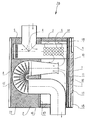
- the combined reflection-absorption exhaust gas silencer 20 shown is designed in a multi-chamber design as a so-called 2-chamber pot. It has a single outer cross section 16 that is essentially oval to rectangular in cross section, a radial intermediate floor 17 being provided, which divides the interior of the muffler 20 into a right-hand reflection chamber 1 as shown in the drawing and an absorption chamber 2 as shown on the left.
- the latter absorption chamber 2 - apart from the interior of the exhaust gas-carrying pipes to be described there - is filled with a sound-absorbing substance 21.
- Both end or outer floors and the radial intermediate floor 17 of the 2-chamber pot, which is parallel to this, are essentially flat.
- Both the exhaust gas inlet and the exhaust gas outlet extend through the outer jacket 16.
- the exhaust gas inlet is located on the side of the absorption chamber 2, while the exhaust gas outlet is located on the side of the reflection chamber 1.
- the muffler 20 has on the exhaust gas inlet side a one-part or multi-part essentially T-shaped exhaust gas inlet pipe 4 with a jacket-side Exhaust gas inlet and a T-shaped exhaust gas branch, one end of which is arranged in the absorption chamber 2 and the other end of which is arranged in the reflection chamber 1.
- the front ends of the T-shaped exhaust branch are closed, and the rectilinear part of the exhaust branch which extends in the axial direction of the muffler has outlet openings 5, 6 on the jacket side both on the absorption chamber side and on the reflection chamber side.
- the first jacket-side outflow openings 5 on the absorption chamber side have a smaller diameter than the second jacket-side outflow openings 6 on the reflection chamber side.
- the muffler 20 On the outlet side, the muffler 20 has a single-part or multi-part exhaust gas outlet pipe 15 with a venturi nozzle 7 on the inlet side parallel to the straight-line part of the T-shaped exhaust branch of the exhaust gas inlet pipe 4 containing the outlet openings 5, 6.
- the Venturi nozzle 7 has its inlet on the reflection chamber side, extends in a conical extension through the wall of the radial intermediate floor 17 into the absorption chamber 2 and merges there into a 180 ° curved section of the exhaust gas outlet pipe 15.
- the further jacket-side outflow openings 8 are in groups along a radial flow cross-section, thus arranged essentially in a star shape according to the drawing in plan view.
- the same number of openings 8 is located in each individual group of a flow cross section.
- the last-mentioned aza number of openings 8 in particular also contains each flow cross-section of the T-shaped exhaust branch in the area of openings 5 of the same size, the tube diameter of the T-shaped exhaust branch preferably having the same tube diameter as the 180 ° elbow section.
- the exhaust gas outlet pipe 15 extends parallel to the Venturi nozzle 7 back into the reflection chamber 1 and finally ends after a curvature on the outer jacket or outside of the outer jacket 16 for a connection to an end pipe of the exhaust system which is not of interest here.
- an edge absorption for structure-borne sound insulation and thermal insulation is provided on the outer floor 18 of the muffler 20, which is on the right-hand side according to the drawing, and on the outer jacket 16.
- the edge absorption on the front outer floor 18 is realized in particular in the form of a package arrangement in a sandwich construction, the package consisting of a perforated inner floor 9, a stainless steel wool molding 10, a structure-borne sound floor 19, an insulating mat in two layers 11, 12 and a pot-like outer floor part 13.
- the edge absorption on the outer jacket 16 is achieved by a perforated inner cage 14 which is concentric with the outer jacket on the inside of the reflection chamber of the outer jacket 16 is arranged at a distance, an insulating mat 3 being provided in the intermediate space.
- Exhaust gas inlet pipe 4 and the exhaust gas outlet pipe 15 are at least partially formed as sheet metal parts, the sheet metal parts being half-shells which are assembled and welded to one another.
- An exhaust pipe (not shown) opens into the reflection chamber 1.
Abstract
Description
Die Erfindung betrifft einen kombinierten Reflexions-Absorptions-Aggas-Schalldämpfer in Mehrkammerbauweise, insbesondere für schwere Nutzfahrzeuge, mit einer Reflexionskammer und einer Absorptionskammer.The invention relates to a combined reflection-absorption aggas muffler in a multi-chamber design, in particular for heavy commercial vehicles, with a reflection chamber and an absorption chamber.
Bei Abgas-Schalldämpfern wird grundsätzlich unterschieden zwischen Reflexionsdämpfern und Absorptionsdämpfern. Beide Bauprinzipien können auch zu einem Schalldämpfer kombiniert werden.With exhaust mufflers, a basic distinction is made between reflection dampers and absorption dampers. Both construction principles can also be combined to a silencer.
Reflexionsschalldämpfer bewirken sowohl eine Reflexion der Schallwellen zur Schallquelle als auch eine Vervielfachung von Schallpunkten (z.B. durch Loch- oder Schlitztraufen), die eine Verbesserung durch Interferenz bewirken.Reflection silencers cause both a reflection of the sound waves to the sound source and a multiplication of sound points (e.g. through perforated or slotted eaves), which bring about an improvement through interference.
Die Dämpfung ist um so wirksamer, je zahlreicher die Reflexionsstellen sind. Im Prinzip besteht ein Reflexionsschalldämpfer aus Kammern, die durch Rohrleitungen miteinander verbunden sind. Reflexionsdämpfer haben besonders im tieffrequenten Bereich eine hohe Wirksamkeit. Bewährt haben sich hauptsächlich sogenannte Dreiwege-Dämpfer mit einer Vielzahl von Varianten. In der Regel sind zwei bis sieben akustische Glieder (z.b. Querschnittssprünge, Umlenkungen, Reihen- und Abzweigresonanten und eingebaute Zwischenrohre) vorhanden. Die Lage des Schalldämpfers in der Leitung bestimmt wesentlich die Güte der Dämpfung. Liegt der Reflexionsdämpfer am Ende der Leitung, ist die Länge des anschließenden Endrohres für die Gesamtdämpfung wichtig. Da der Außenmantel direkt mit dem Abgas in Berührung kommt, können sehr hohe Oberflächentemperaturen entstehen - insbesondere, weil Schalldämpfer zur Herabsetzung des Luftwiderstandes immer häufiger in die Unterbodengruppe integriert werden. Zur Verminderung der Wärmeabgabe an die Unterbodengruppe kann der Außenmantel doppelwandig und mit einer Isolationsschicht (z.B. aus Mineral- oder Keramikfasern) ausgeführt werden.The more effective the attenuation, the more effective the attenuation. In principle, a reflection silencer consists of chambers that are connected to each other by pipes. Reflection dampers are particularly effective in the low-frequency range. So-called three-way dampers with a large number of variants have proven their worth. As a rule, there are two to seven acoustic elements (e.g. cross-sectional jumps, deflections, row and Branch resonants and built-in intermediate pipes) available. The position of the muffler in the pipe essentially determines the quality of the damping. If the reflection damper is at the end of the line, the length of the tailpipe is important for the overall attenuation. Since the outer jacket comes into direct contact with the exhaust gas, very high surface temperatures can arise - especially because silencers are increasingly integrated into the underbody group to reduce air resistance. To reduce the heat given off to the underbody group, the outer jacket can be double-walled and with an insulation layer (e.g. made of mineral or ceramic fibers).
Absorptionsschalldämpfer bestehen im Prinzip aus einer perforierten Rohrleitung, durch die das Abgas geleitet wird und die von einer mit Schallschluckstoff ausgekleideten Kammer umgeben ist. Die Schallwellen dringen über die Rundloch-, Schlitzloch- oder Schlitzbrückenperforation des abgasführenden Innenrohres in den Schallschluckstoff. Durch Reibung im Absorptionsstoff wird die Schallenergie in Wärme umgewandelt. Die Wirkung eines Absorptionsdämpfers hängt u.a. von der Geometrie der Perforation, vom Schallabsorptionsgrad und von der Stopfdichte des verwendeten Schluckstoffes ab. Absorptionsschalldämpfer bewirken eine breitbandige Dämpfung und verursachen in der Regel einen geringeren Druckverlust als vergleichbare Reflexionsschalldämpfer. Der Schallschluckstoff muß gegen thermische und chemische Einwirkungen beständig sein, aber auch resistent gegen hochfrequente Abgasdruckpulsation und mechanische Vibration. Als Schallschluckstoff wird Mineral- bzw. Metallwolle oder eine Kombination von beiden eingesetzt. In der Regel wird Basaltwolle verwendet, gelegentlich in Kombination mit Edelstahlwolle.In principle, absorption silencers consist of a perforated pipe through which the exhaust gas is directed and which is surrounded by a chamber lined with sound-absorbing material. The sound waves penetrate into the sound absorbing material via the round hole, slot hole or slot bridge perforation of the exhaust pipe carrying the exhaust gas. The sound energy is converted into heat by friction in the absorption material. The effect of an absorption damper depends, among other things. on the geometry of the perforation, the degree of sound absorption and the density of the stuffing used. Absorption silencers provide broadband damping and generally cause less pressure loss than comparable reflection silencers. The sound absorbent must be resistant to thermal and chemical effects, but also resistant to high-frequency exhaust gas pressure pulsation and mechanical vibration. Mineral or metal wool or a combination of the two is used as sound absorption material. Basalt wool is usually used, occasionally in combination with stainless steel wool.
Zur akustischen Feinabstimmung können z. B. Lochtraufen oder Venturidüsen vorgesehen sein. Letztgenannte Venturidusen werden gegen tieffrequente Schallanteile eingesetzt.For acoustic fine tuning z. B. perforated eaves or Venturi nozzles can be provided. The latter will be venturi used against low-frequency sound components.
Der Erfindung liegt die Aufgabe zugrunde, einen kombinierten Absorptions-Reflexions-Abgas-Schalldämpfer der eingangs genannten Art zu schaffen, welcher einfach aufgebaut ist und insbesondere als 78 dB-Dämpfer für schwere Nutzfahrzeuge mit einer 6- und 8-Zylinder-Motorisierung geeignet ist.The invention has for its object to provide a combined absorption-reflection exhaust gas silencer of the type mentioned, which is simple in construction and is particularly suitable as a 78 dB damper for heavy commercial vehicles with a 6 and 8 cylinder engine.
Gelöst wird die Aufgabe durch einen Schalldämpfer der im Patentanspruch 1 angegebenen Art.The object is achieved by a silencer of the type specified in claim 1.
Vorteilhaft weitergebildet wird der Schalldämpfer durch die Merkmale nach den Ansprüchen 2 bis 18.The muffler is advantageously further developed by the features according to
Das Wesen der Erfindung ist bei einem gattungsgemäßen Schalldämpfer darin zu sehen, daß ein im wesentlichen T-förmiges Abgas-Eintrittsrohr mit einem mantelseitigen Abgas-Einlaß und einer T-förmigen Abgas-Aufzweigung vorgesehen ist, deren eines Ende in der Absorptionskammer und deren anderes Ende in der Reflexionskammer liegt, wobei die stirnseitigen Enden der T-förmigen Abgas-Aufzweigung geschlossen und mantelseitige Ausströmöffnungen sowohl auf der Absorptionskammerseite als auch auf der Reflexionskammerseite ausgebildet sind.The essence of the invention is to be seen in a generic muffler in that a substantially T-shaped exhaust gas inlet pipe is provided with a jacket-side exhaust gas inlet and a T-shaped exhaust gas branch, one end of which in the absorption chamber and the other end lies in the reflection chamber, the front ends of the T-shaped exhaust branch being closed and jacket-side outflow openings being formed both on the absorption chamber side and on the reflection chamber side.
Bevorzugt sind die der Absorptionskammer zugeordneten ersten mantelseitigen Austrittsöffnungen kleiner als die der Reflexionskammer zugeordneten zweiten mantelseitigen Austrittsöffnungen.The first jacket-side outlet openings assigned to the absorption chamber are preferably smaller than the second jacket-side outlet openings assigned to the reflection chamber.
Die ersten und zweiten mantelseitigen Austrittsöffnungen können auf der dem Abgas-Einlaß vorzugsweise abgewandten Mantelseite der Abgas-Abzweigung ausgebildet sein.The first and second jacket-side outlet openings can be formed on the jacket side of the exhaust gas branch, preferably facing away from the exhaust gas inlet.
Ein besonders vorteilhafte Weiterbildung der Erfindung kennzeichnet sich dadurch, daß ein Abgas-Austrittsrohr vorgesehen ist, dessen Einlaß in der Reflexionskammer angeordnet ist und sich zumindest teilweise durch die Absorptionskammer erstreckt, wobei das Abgas-Austrittsrohr im der Absorptionskammer zugeordneten Mantelabschnitt weitere Ausströmöffnungen enthält.A particularly advantageous development of the invention is characterized in that an exhaust gas outlet pipe is provided is whose inlet is arranged in the reflection chamber and extends at least partially through the absorption chamber, the exhaust gas outlet pipe in the jacket section associated with the absorption chamber containing further outflow openings.
Der Einlaß des Abgas-Austrittsrohrs ist zweckmäßigerweise mit einer Venturidüse bzw. Ausströmdüse versehen.The inlet of the exhaust gas outlet pipe is expediently provided with a Venturi nozzle or outflow nozzle.
Insbesondere umfaßt der der Absorptionskammer zugeordnete Abschnitt des Abgas-Austrittsrohrs einen um ca. 180° gebogenen Rohrbereich, welcher die weiteren Abgas-Ausströmöffnungen enthält.In particular, the section of the exhaust gas outlet pipe assigned to the absorption chamber comprises a pipe region which is bent by approximately 180 ° and which contains the further exhaust gas outflow openings.
Der Schalldämpfer ist bevorzugt als ein 2-Kammer-Topf mit einem einzigen Außenmantel und einem radialen Zwischenboden ausgebildet, welcher den Innenraum des Schalldämpfers in die Absorptionskammer und die Reflexionskammer unterteilt, wobei auf der Reflexionskammerseite am Außenmantel und am stirnseitigen Außenboden eine Randabsorption integriert ist.The muffler is preferably designed as a 2-chamber pot with a single outer jacket and a radial intermediate floor, which divides the interior of the muffler into the absorption chamber and the reflection chamber, with an edge absorption being integrated on the reflection chamber side on the outer jacket and on the front-side outer floor.
Die Randabsorption des stirnseitigen Außenbodens ist insbesondere in Form einer Paketanordnung in Sandwichbauweise ausgeführt, bestehend aus einem perforierten Innenboden, einem Edelstahlwolle-Formstück, einem Körperschallboden, einer Isoliermatte in zwei Lagen und einem topfartigen Außenbodenteil.The edge absorption of the front outer floor is in particular in the form of a package arrangement in a sandwich construction, consisting of a perforated inner floor, a stainless steel wool fitting, a structure-borne sound floor, an insulating mat in two layers and a pot-like outer floor part.
Die Randabsorption des Außenmantels des Schalldämpfers ist bevorzugt ein auf der Reflexionskammer-Innenseite des Außenmantels angeordneter perforierter Innenkäfig mit einer zwischengeordneten Isoliermatte, die nicht nur für eine gute Körperschalldämmung, sondern auch für ein gute thermische Isolation des Außenmantels sorgt.The edge absorption of the outer shell of the muffler is preferably a perforated inner cage arranged on the inside of the reflection chamber of the outer shell with an intermediate insulating mat, which not only ensures good structure-borne sound insulation but also good thermal insulation of the outer shell.
Bevorzugt ist ein Abgas-Eintrittsrohr mit einem Eingang vorgesehen, welcher sich durch den Außenmantel des Schalldämpfers erstreckt, und zwar insbesondere auf der Seite der Absorptionskammer.An exhaust gas inlet pipe is preferably provided with an inlet which extends through the outer jacket of the muffler, in particular on the side of the absorption chamber.
Das Abgas-Austrittsrohr besitzt insbesondere einen Auslaß, welcher sich ebenfalls durch den Außenmatel des Schalldämpfers erstreckt, jedoch insbesondere auf der Seite der Reflexionskammer.The exhaust gas outlet pipe has in particular an outlet which also extends through the outer shell of the muffler, but in particular on the side of the reflection chamber.
Abgas-Eintrittsrohr und Abgas-Austrittsrohr sind insbesondere zumindest teilweise Blechformteile, welche aus Halbschalen zusammengesetzt und miteinander verschweißt sein können.Exhaust gas inlet pipe and exhaust gas outlet pipe are in particular at least partially formed sheet metal parts which can be composed of half-shells and welded to one another.
Der der Absorptionskammer zugeordnete Bereich des Abgas-Austrittsrohres kann zumindest teilweise mit einer Lage aus Edelstahlwolle umwickelt sein.The area of the exhaust gas outlet pipe assigned to the absorption chamber can be at least partially wrapped with a layer of stainless steel wool.
Bevorzugt mündet in die Reflexionskammer ein Abluftröhrchen ein.An exhaust air tube preferably opens into the reflection chamber.
Im Ergebnis wird durch die Erfindung ein kombinierter Reflexions-/Absorptions-Schalldämpfer mit schalldämpfenden Elementen geschaffen, der eine hohe Dämpfung im Hinblick auf Mündungsschall und Körperschall bei einem niedrigen Gegendruck-Niveau besitzt. Das Schalldämpfersystem eigent sich besonders für schwere Nutzfahrzeuge. Der 2-Kammer-Dämpfer besitzt eine integrierte Randabsorption am Außenmantel und am stirnseitigen Außenboden auf der Reflexionskammerseite. Der Schalldämpfer-Eintritt erfolgt über eine T-förmige Ausströmung des inneren Eintrittsrohrs, welches über eine Perforation an die Absorptionskammer und über eine Ausströmbrause an die Reflexionskammer gekoppelt ist. Der Schalldämpferaustritt erfolgt über eine Ausströmdüse aus der Reflexionskammer, wobei durch eine Perforation eine Kopplung an die Absorptionskammer vorgesehen ist.As a result, a combined reflection / absorption muffler with sound-absorbing elements is created by the invention, which has a high damping in terms of muzzle sound and structure-borne noise at a low back pressure level. The silencer system is particularly suitable for heavy commercial vehicles. The 2-chamber damper has an integrated edge absorption on the outer jacket and on the front outer floor on the reflection chamber side. The muffler inlet is via a T-shaped outflow of the inner inlet pipe, which is coupled to the absorption chamber via a perforation and to the reflection chamber via an outflow shower. The silencer exits via an outlet nozzle from the reflection chamber, wherein a coupling to the absorption chamber is provided by a perforation.
Die Erfindung wird nachfolgend anhand eines Ausführungsbeispiels unter Bezugnahme auf die beigefügte Zeichnung näher beschrieben, deren einzige Figur einen schematischen Axialschnitt durch einen kombinierten Reflexions-/Absorptions-Schalldämpfer einer Abgasanlage eines schweren Nutzfahrzeuges zeigt.The invention is described below with reference to an embodiment with reference to the accompanying drawing, the single figure shows a schematic axial section through a combined reflection / absorption muffler of an exhaust system of a heavy commercial vehicle.
Der dargestellte kombinierte Reflexions-Absorptions-Abgas-Schalldämpfer 20 ist in Mehrkammerbauweise als sogenannter 2-Kammer-Topf ausgeführt. Er besitzt einen einzigen im Querschnitt im wesentlichen ovalen bis rechteckigen Außenmantel 16, wobei ein radialer Zwischenboden 17 vorgesehen ist, der den Innenraum des Schalldämpfers 20 in eine gemäß Zeichnung rechte Reflexionskammer 1 und eine gemäß Zeichnung linke Absorptionskammer 2 unterteilt. Letztgenannte Absorptionskammer 2 ist - abgesehen vom Innenraum der noch zu beschreibenden abgasführenden dortigen Rohre - mit einem Schallschluckstoff 21 ausgefüllt.The combined reflection-absorption
Beide End- oder Außenböden sowie der hierzu paralle radiale Zwischenboden 17 des 2-Kammer-Topfes sind im wesentlichen plan.Both end or outer floors and the radial
Sowohl der Abgas-Eingang als auch der Abgas-Auslaß erstrecken sich durch den Außenmantel 16. Der Abgas-Eingang liegt hierbei auf der Seite der Absorptionskammer 2, während der Abgas-Auslaß auf der Seite der Reflexionskammer 1 gelegen ist.Both the exhaust gas inlet and the exhaust gas outlet extend through the
Im einzelnen besitzt der Schalldämpfer 20 auf der Abgas-Eintrittsseite ein ein- oder mehrteiliges im wesentlichen T-förmiges Abgas-Eintrittsrohr 4 mit einem mantelseitigen Abgas-Einlaß und einer T-förmigen Abgas-Aufzweigung, deren eines Ende in der Absorptionskammer 2 und deren anderes Ende in der Reflexionskammer 1 angeordnet ist. Die stirnseitigen Enden der T-förmigen Abgas-Aufzweigung sind geschlossen, und es besitzt der geradlinige in Axialrichtung des Schalldämpfers sich erstreckende Teil der Abgas-Aufzweigung mantelseitige Ausströmöffnungen 5, 6 sowohl auf der Absorptionskammerseite als auch auf der Reflexionskammerseite.In particular, the
Die ersten mantelseitigen Ausströmöffnungen 5 auf der Absorptionskammerseite besitzen einen kleineren Durchmesser als die zweiten mantelseitigen Ausströmöffnungen 6 auf der Reflexionskammerseite.The first jacket-
Auf der Austrittsseite besitzt der Schalldämpfer 20 ein ein- oder oder mehrteiliges Abgas-Austrittsrohr 15 mit einer eingangsseitigen Venturidüse 7 parallel zum geradlinigen die Ausströmöffnungen 5, 6 enthaltenden Teil der T-förmigen Abgas-Aufzweigung des Abgas-Eintrittsrohrs 4.On the outlet side, the
Die Venturidüse 7 hat ihren Einlaß auf der Reflexionskammerseite, erstreckt sich in konischer Erweiterung durch die Wand des radialen Zwischenbodens 17 in die Absorptionskammer 2 und geht dort in einen 180°-Bogenabschnitt des Abgas-Austrittsrohres 15 über.The Venturi
In dem in der Absorptionskammer 2 gelegenen 180°-Bogenabschnitt befinden sich weitere mantelseitige Ausströmöffnungen 8 etwa in der Größe der ersten Auströmöffnungen 5, wobei der 180°-Bogenabschnitt in der Absorptionskammer 2 zumindest im Bereich der weiteren Ausströmöffnungen 8 mit einer Lage aus Edelstahlwolle umwickelt ist.In the 180 ° arc section located in the
Die weiteren mantelseitigen Ausströmöffnungen 8 sind gruppenweise längs eines radialen Durchströmungsquerschnittes, also gemäß Zeichnung in Draufsicht im wesentlichen sternförmig angeordnet.The further jacket-
In jeder Einzelgruppe eines Durchströmungsquerschnittes befindet sich die gleiche Anzahl an Öffnungen 8.The same number of
Letztgenannte Azizahl an Öffnungen 8 enthält insbesondere auch jeder Durchströmungsquerschnitt der T-förmigen Abgas-Aufzweigung im Bereich gleich dimensionierter Öffnungen 5, wobei der Rohrdurchmesser der T-förmigen Abgas-Aufzweigung vorzugsweise den gleichen Rohrdurchmesser wie der 180°-Bogenabschnitt aufweist.The last-mentioned aza number of
Nach dem 180-Bogenabschnitt erstreckt sich das Abgas-Austrittsrohr 15 parallel zur Venturidüse 7 wieder in die Reflexionskammer 1 zurück und endigt schließlich nach einer Krümmung am Außenmantel bzw. außerhalb des Außenmantels 16 für einen hier nicht interessierenden Anschluß an ein Endrohr der Abgasanlage.After the 180-bend section, the exhaust
Auf der Seite der Reflexionskammer 1 ist am gemäß Zeichnung rechten stirnseitigen Außenboden 18 des Schalldämpfers 20 sowie am Außenmantel 16 eine Randabsorption zur Körperschalldämmung und thermischen Isolation vorgesehen.On the side of the reflection chamber 1, an edge absorption for structure-borne sound insulation and thermal insulation is provided on the
Die Randabsorption am stirnseitigen Außenboden 18 ist insbesondere in Form einer Paketanordnung in Sandwichbauweise realisiert, wobei das Paket aus einem perforierten Innenboden 9, einem Edelstahlwolle-Formstück 10, einem Körperschallboden 19, einer Isoliermatte in zwei Lagen 11, 12 und einem topfartigen Außenbodenteil 13 besteht.The edge absorption on the front
Die Randabsorption am Außenmantel 16 wird durch einen perforierten Innenkäfig 14 erzielt, der konzentrisch zum Außenmantel auf der Reflexionskammer-Innenseite des Außenmantels 16 mit Abstand angeordnet ist, wobei im Zwischenraum eine Isoliermatte 3 vorgesehen ist.The edge absorption on the
Abgas-Eintrittsrohr 4 und das Abgas-Austrittsrohr 15 sind zumindest teilweise als Blechformteile ausgebildet, wobei die Blechformteile Halbschalen sind, die zusammengesetzt und miteinander verschweißt sind.Exhaust gas inlet pipe 4 and the exhaust
In die Reflexionskammer 1 mündet ein (nicht veranschaulichtes) Abluftröhrchen ein.An exhaust pipe (not shown) opens into the reflection chamber 1.
Es sei noch angemerkt, daß in den Unteransprüchen enthaltene selbständig schutzfähige Merkmale trotz der vorgenommenen formalen Rückbeziehung auf den Hauptanspruch entsprechenden eigenständigen Schutz haben sollen. Im übrigen fallen sämtliche in den gesamten Anmeldungsunterlagen enthaltenen erfinderischen Merkmale in den Schutzumfang der Erfindung.It should also be noted that, despite the formal reference back to the main claim, the independently protectable features contained in the subclaims should have appropriate independent protection. For the rest, all inventive features contained in the entire application documents fall within the scope of the invention.
Claims (16)
gekennzeichnet durch
ein im wesentlichen T-förmiges Abgas-Eintrittsrohr (4) mit einem mantelseitigen Abgas-Einlaß und einer T-förmigen Abgas-Aufzweigung, deren eines Ende in der Absorptionskammer (2) und deren anderes Ende in der Reflexionskammer (1) angeordnet ist, wobei die stirnseitigen Enden der T-förmigen Abgas-Aufzweigung geschlossen und mantelseitige Ausströmöffnungen (5, 6) in der Abgas-Aufzweigung sowohl auf der Absorptionskammerseite als auch auf der Reflexionskammerseite ausgebildet sind.Combined reflection-absorption exhaust gas silencer (20) in a multi-chamber construction, in particular for heavy commercial vehicles, with a reflection chamber (1) and an absorption chamber (2),
marked by
a substantially T-shaped exhaust gas inlet pipe (4) with a jacket-side exhaust gas inlet and a T-shaped exhaust branch, one end of which is arranged in the absorption chamber (2) and the other end of which is arranged in the reflection chamber (1), wherein the front ends of the T-shaped exhaust branch are closed and jacket-side outflow openings (5, 6) are formed in the exhaust branch both on the absorption chamber side and on the reflection chamber side.
dadurch gekennzeichnet,
daß die der Absorptionskammer (2) zugeordneten ersten mantelseitigen Ausströmöffnungen (5) kleiner als die der Reflexionskammer (1) zugeordneten zweiten mantelseitigen Ausströmöffnungen (6) sind.Silencer according to claim 1,
characterized,
that the first jacket-side outflow openings (5) assigned to the absorption chamber (2) are smaller than the second jacket-side outflow openings (6) assigned to the reflection chamber (1).
dadurch gekennzeichnet,
daß die ersten und zweiten mantelseitigen Ausströmöffnungen (5, 6) auf der dem Abgas-Einlaß vorzugsweise abgewandten Mantelseite der Abgas-Abzweigung angeordnet sind.Silencer according to claim 2 or 3,
characterized,
that the first and second jacket-side outflow openings (5, 6) are arranged on the jacket side of the exhaust gas branch which preferably faces away from the exhaust gas inlet.
dadurch gekennzeichnet,
daß ein Abgas-Austrittsrohr (15) vorgesehen ist, dessen Einlaß in der Reflexionskammer (1) angeordnet ist und sich zumindest teilweise durch die Absorptionskammer (2) erstreckt, wobei das Abgas-Austrittsrohr (15) im der Absorptionskammer (2) zugeordneten Mantelabschnitt weitere Ausströmöffnungen (8) aufweist.Silencer according to one of claims 1 to 3,
characterized,
that an exhaust gas outlet pipe (15) is provided, the inlet of which is arranged in the reflection chamber (1) and extends at least partially through the absorption chamber (2), the exhaust gas outlet pipe (15) in the jacket section associated with the absorption chamber (2) Outflow openings (8).
dadurch gekennzeichnet,
daß der Einlaß des Abgas-Austrittsrohrs mit einer Venturidüse (7) versehen ist.Silencer according to claim 4,
characterized,
that the inlet of the exhaust gas outlet pipe is provided with a Venturi nozzle (7).
dadurch gekennzeichnet,
daß der Auslaß des Abgas-Austrittsrohrs (15) auf der Seite der Reflexionskammer (1) liegt.Silencer according to claim 4 or 5,
characterized,
that the outlet of the exhaust gas outlet pipe (15) is on the side of the reflection chamber (1).
dadurch gekennzeichnet,
daß der der Absorptionskammer (2) zugeordnete Abschnitt des Abgas-Austrittsrohrs (15) einen um ca. 180° gebogenen Rohrbereich umfaßt, welcher die weiteren Abgas-Ausströmöffnungen (8) enthält.Silencer according to claim 6,
characterized,
that the section of the exhaust gas outlet pipe (15) assigned to the absorption chamber (2) comprises a pipe region which is bent by approximately 180 ° and which contains the further exhaust gas outflow openings (8).
gekennzeichnet durch
einen 2-Kammer-Topf mit einem einzigen Außenmantel (16) und einem radialen Zwischenboden (17), welcher den Innenraum des Schalldämpfers (20) in die Absorptionskammer (2) und die Reflexionskammer (1) unterteilt, wobei auf der Reflexionskammerseite am Außenmantel (16) und am stirnseitigen Außenboden (18) eine Randabsorption integriert ausgebildet ist.Silencer according to one of claims 1 to 7,
marked by
a 2-chamber pot with a single outer jacket (16) and a radial intermediate floor (17) which divides the interior of the muffler (20) into the absorption chamber (2) and the reflection chamber (1), whereby on the reflection chamber side on the outer jacket ( 16) and an edge absorption is integrally formed on the front outer bottom (18).
dadurch gekennzeichnet,
daß der stirnseitige Außenboden (18) eine Paketanordnung in Sandwichbauweise ist, bestehend aus einem perforierten Innenboden (9), einem Edelstahlwolle-Formstück (10), einem Körperschallboden (19), einer Isoliermatte in zwei Lagen (11, 12) und einem topfartigen Außenbodenteil (13).Silencer according to claim 8,
characterized,
that the front outer floor (18) is a package arrangement in sandwich construction, consisting of a perforated inner floor (9), a stainless steel wool fitting (10), a structure-borne soundboard (19), an insulating mat in two layers (11, 12) and a pot-like outer bottom part (13).
dadurch gekennzeichnet,
daß auf der Reflexionskammer-Innenseite des Außenmantels (16) ein perforierter Innenkäfig (14) mit einer zwischengeordneten Isoliermatte (3) zur Körperschalldämmung und thermischen Isolation des Außenmantels (16) vorgesehen ist.Silencer according to claim 8 or 9,
characterized,
that a perforated inner cage (14) with an intermediate insulating mat (3) for structure-borne sound insulation and thermal insulation of the outer jacket (16) is provided on the inside of the reflection chamber of the outer jacket (16).
dadurch gekennzeichnet,
daß das im wesentliche T-förmige Abgas-Eintrittsrohr (4) einen außenmantelseitigen Abgas-Eingang aufweist.Silencer according to one of claims 8 to 10,
characterized,
that the substantially T-shaped exhaust gas inlet pipe (4) has an outer jacket-side exhaust gas inlet.
dadurch gekennzeichnet,
daß das Abgas-Austrittsrohr (15) einen außenmantelseitigen Abgas-Auslaß aufweist.Silencer according to one of claims 8 to 11,
characterized,
that the exhaust gas outlet pipe (15) has an outer jacket-side exhaust gas outlet.
dadurch gekennzeichnet,
daß das Abgas-Eintrittsrohr (4) und das Abgas-Austrittsrohr (15) zumindest teilweise Blechformteile sind.Silencer according to one of claims 1 to 12,
characterized,
that the exhaust gas inlet pipe (4) and the exhaust gas outlet pipe (15) are at least partially sheet metal parts.
dadurch gekennzeichnet,
daß die Blechformteile aus Halbschalen zusammengesetzt und verschweißt sind.A silencer according to claim 13,
characterized,
that the sheet metal parts are composed of half shells and welded.
dadurch gekennzeichnet,
daß der der Absorptionskammer (2) zugeordnete Bereich des Abgas-Austrittsrohres (15) zumindest teilweise mit einer Lage aus Edelstahlwolle umwickelt ist.Silencer according to one of claims 1 to 14,
characterized,
that the area of the exhaust gas outlet pipe (15) assigned to the absorption chamber (2) is at least partially wrapped with a layer of stainless steel wool.
dadurch gekennzeichnet,
daß in die Reflexionskammer (1) ein Abluftröhrchen einmündet.Silencer according to one of claims 1 to 15,
characterized,
that an exhaust pipe opens into the reflection chamber (1).
Applications Claiming Priority (2)
| Application Number | Priority Date | Filing Date | Title |
|---|---|---|---|
| DE19608273 | 1996-03-05 | ||
| DE19608273A DE19608273A1 (en) | 1996-03-05 | 1996-03-05 | Combined reflection-absorption exhaust silencer in multi-chamber design |
Publications (3)
| Publication Number | Publication Date |
|---|---|
| EP0794324A2 true EP0794324A2 (en) | 1997-09-10 |
| EP0794324A3 EP0794324A3 (en) | 1998-05-06 |
| EP0794324B1 EP0794324B1 (en) | 2002-08-28 |
Family
ID=7787151
Family Applications (1)
| Application Number | Title | Priority Date | Filing Date |
|---|---|---|---|
| EP97102548A Expired - Lifetime EP0794324B1 (en) | 1996-03-05 | 1997-02-18 | Combined multiple chamber reflection-absorption exhaust silencer |
Country Status (2)
| Country | Link |
|---|---|
| EP (1) | EP0794324B1 (en) |
| DE (2) | DE19608273A1 (en) |
Cited By (4)
| Publication number | Priority date | Publication date | Assignee | Title |
|---|---|---|---|---|
| WO2008073137A1 (en) * | 2006-12-14 | 2008-06-19 | Ocv Intellectual Capital, Llc | Long fiber thermoplastic composite muffler system with integrated reflective chamber |
| WO2008110252A1 (en) * | 2007-03-09 | 2008-09-18 | Festo Ag & Co. Kg | Pressurized air muffler for pneumatic applications |
| US7730996B2 (en) | 2006-04-12 | 2010-06-08 | Ocv Intellectual Capital, Llc | Long fiber thermoplastic composite muffler system with integrated crash management |
| AT510788A1 (en) * | 2010-10-28 | 2012-06-15 | Avl List Gmbh | EXHAUST MUFFLER ARRANGEMENT |
Families Citing this family (2)
| Publication number | Priority date | Publication date | Assignee | Title |
|---|---|---|---|---|
| US7934580B2 (en) | 2006-04-12 | 2011-05-03 | Ocv Intellectual Capital, Llc | Long fiber thermoplastic composite muffler system |
| CN109386505B (en) | 2017-08-09 | 2022-02-11 | 开利公司 | Silencer for refrigerating device and refrigerating device |
Family Cites Families (3)
| Publication number | Priority date | Publication date | Assignee | Title |
|---|---|---|---|---|
| DE866744C (en) * | 1950-11-07 | 1953-02-12 | Eberspaecher J | Sound absorber for cracking noises especially contained in the exhaust of two-stroke engines and extremely steep pressure front |
| GB1446553A (en) * | 1972-12-06 | 1976-08-18 | Nicoll W L G | Mufflers |
| DE9308419U1 (en) * | 1993-06-05 | 1994-10-13 | Roth Technik Gmbh | Silencer for preferably gaseous media |
-
1996
- 1996-03-05 DE DE19608273A patent/DE19608273A1/en not_active Withdrawn
-
1997
- 1997-02-18 DE DE59708027T patent/DE59708027D1/en not_active Expired - Fee Related
- 1997-02-18 EP EP97102548A patent/EP0794324B1/en not_active Expired - Lifetime
Non-Patent Citations (1)
| Title |
|---|
| None |
Cited By (5)
| Publication number | Priority date | Publication date | Assignee | Title |
|---|---|---|---|---|
| US7730996B2 (en) | 2006-04-12 | 2010-06-08 | Ocv Intellectual Capital, Llc | Long fiber thermoplastic composite muffler system with integrated crash management |
| WO2008073137A1 (en) * | 2006-12-14 | 2008-06-19 | Ocv Intellectual Capital, Llc | Long fiber thermoplastic composite muffler system with integrated reflective chamber |
| WO2008110252A1 (en) * | 2007-03-09 | 2008-09-18 | Festo Ag & Co. Kg | Pressurized air muffler for pneumatic applications |
| AT510788A1 (en) * | 2010-10-28 | 2012-06-15 | Avl List Gmbh | EXHAUST MUFFLER ARRANGEMENT |
| AT510788B1 (en) * | 2010-10-28 | 2012-10-15 | Avl List Gmbh | EXHAUST MUFFLER ARRANGEMENT |
Also Published As
| Publication number | Publication date |
|---|---|
| EP0794324A3 (en) | 1998-05-06 |
| DE59708027D1 (en) | 2002-10-02 |
| EP0794324B1 (en) | 2002-08-28 |
| DE19608273A1 (en) | 1997-09-11 |
Similar Documents
| Publication | Publication Date | Title |
|---|---|---|
| EP1715189B1 (en) | Noise attenuator designed and meant for a compressor | |
| EP0455623B1 (en) | Exhaust silencer, especially for a two-stroke engine with catalytic converter | |
| DE2534556B2 (en) | Silencers for gas flows | |
| DE602005005461T2 (en) | MUFFLER FOR EXHAUST SYSTEM OF VEHICLES | |
| DE2908506C2 (en) | Silencers for internal combustion engines | |
| DE69723870T2 (en) | DEVICE AND METHOD FOR SOUND ABSORBATION IN A TRANSPORT SYSTEM FOR GASEOUS SUBSTANCES AND APPLICATION OF SUCH A DEVICE IN AN EXHAUST SYSTEM OF A SHIP | |
| EP0931913B1 (en) | Exhaust silencer for internal combustion engines | |
| DE2545364C3 (en) | ||
| DE1292667B (en) | Silencer for flowing gases | |
| EP0794324B1 (en) | Combined multiple chamber reflection-absorption exhaust silencer | |
| DE2537946C2 (en) | Exhaust system | |
| DE1299647B (en) | Sound-absorbing gas pipe | |
| DE3125083C2 (en) | Mufflers for vehicle engines | |
| DE2930775C2 (en) | Absorption silencer for exhaust gases | |
| DE3406282C2 (en) | Reflection silencers for internal combustion engines | |
| DE6608356U (en) | EXHAUST SYSTEM WITH SILENCER. | |
| DE3713448C2 (en) | ||
| DE1426198A1 (en) | Silencer | |
| DE3836589C2 (en) | Compact silencer for commercial vehicles | |
| DE19706883C2 (en) | Exhaust silencers for vehicles with internal combustion engines | |
| DE2910370C2 (en) | Exhaust system for internal combustion engines with two exhaust lines arranged in parallel | |
| DE1426202A1 (en) | Exhaust silencer | |
| CH694776A5 (en) | Silencer for attenuating noises that occur during leakage of exhaust gases from an exhaust opening. | |
| DE3444924C2 (en) | ||
| DE1200007B (en) | Sound absorber with a backdrop for attenuating noise emitted from a wall opening or the like |
Legal Events
| Date | Code | Title | Description |
|---|---|---|---|
| PUAI | Public reference made under article 153(3) epc to a published international application that has entered the european phase |
Free format text: ORIGINAL CODE: 0009012 |
|
| AK | Designated contracting states |
Kind code of ref document: A2 Designated state(s): DE FR IT SE |
|
| PUAL | Search report despatched |
Free format text: ORIGINAL CODE: 0009013 |
|
| AK | Designated contracting states |
Kind code of ref document: A3 Designated state(s): DE FR IT SE |
|
| RHK1 | Main classification (correction) |
Ipc: F01N 1/06 |
|
| 17P | Request for examination filed |
Effective date: 19981223 |
|
| 17Q | First examination report despatched |
Effective date: 20010405 |
|
| GRAG | Despatch of communication of intention to grant |
Free format text: ORIGINAL CODE: EPIDOS AGRA |
|
| RAP1 | Party data changed (applicant data changed or rights of an application transferred) |
Owner name: J. EBERSPAECHER GMBH & CO. KG |
|
| GRAG | Despatch of communication of intention to grant |
Free format text: ORIGINAL CODE: EPIDOS AGRA |
|
| GRAH | Despatch of communication of intention to grant a patent |
Free format text: ORIGINAL CODE: EPIDOS IGRA |
|
| GRAH | Despatch of communication of intention to grant a patent |
Free format text: ORIGINAL CODE: EPIDOS IGRA |
|
| GRAA | (expected) grant |
Free format text: ORIGINAL CODE: 0009210 |
|
| AK | Designated contracting states |
Kind code of ref document: B1 Designated state(s): DE FR IT SE |
|
| REF | Corresponds to: |
Ref document number: 59708027 Country of ref document: DE Date of ref document: 20021002 |
|
| ET | Fr: translation filed | ||
| PLBE | No opposition filed within time limit |
Free format text: ORIGINAL CODE: 0009261 |
|
| STAA | Information on the status of an ep patent application or granted ep patent |
Free format text: STATUS: NO OPPOSITION FILED WITHIN TIME LIMIT |
|
| 26N | No opposition filed |
Effective date: 20030530 |
|
| PGFP | Annual fee paid to national office [announced via postgrant information from national office to epo] |
Ref country code: FR Payment date: 20040217 Year of fee payment: 8 |
|
| PGFP | Annual fee paid to national office [announced via postgrant information from national office to epo] |
Ref country code: SE Payment date: 20040224 Year of fee payment: 8 |
|
| PG25 | Lapsed in a contracting state [announced via postgrant information from national office to epo] |
Ref country code: SE Free format text: LAPSE BECAUSE OF NON-PAYMENT OF DUE FEES Effective date: 20050219 |
|
| EUG | Se: european patent has lapsed | ||
| PG25 | Lapsed in a contracting state [announced via postgrant information from national office to epo] |
Ref country code: FR Free format text: LAPSE BECAUSE OF NON-PAYMENT OF DUE FEES Effective date: 20051031 |
|
| REG | Reference to a national code |
Ref country code: FR Ref legal event code: ST Effective date: 20051031 |
|
| PGFP | Annual fee paid to national office [announced via postgrant information from national office to epo] |
Ref country code: DE Payment date: 20090228 Year of fee payment: 13 |
|
| PGFP | Annual fee paid to national office [announced via postgrant information from national office to epo] |
Ref country code: IT Payment date: 20090227 Year of fee payment: 13 |
|
| PG25 | Lapsed in a contracting state [announced via postgrant information from national office to epo] |
Ref country code: DE Free format text: LAPSE BECAUSE OF NON-PAYMENT OF DUE FEES Effective date: 20100901 |
|
| PG25 | Lapsed in a contracting state [announced via postgrant information from national office to epo] |
Ref country code: IT Free format text: LAPSE BECAUSE OF NON-PAYMENT OF DUE FEES Effective date: 20100218 |