EP0794103B1 - Dispositif antirotation de corps de colonne de direction de véhicule automobile - Google Patents
Dispositif antirotation de corps de colonne de direction de véhicule automobile Download PDFInfo
- Publication number
- EP0794103B1 EP0794103B1 EP97400420A EP97400420A EP0794103B1 EP 0794103 B1 EP0794103 B1 EP 0794103B1 EP 97400420 A EP97400420 A EP 97400420A EP 97400420 A EP97400420 A EP 97400420A EP 0794103 B1 EP0794103 B1 EP 0794103B1
- Authority
- EP
- European Patent Office
- Prior art keywords
- coupling surfaces
- support member
- pair
- adjustment
- rotation
- Prior art date
- Legal status (The legal status is an assumption and is not a legal conclusion. Google has not performed a legal analysis and makes no representation as to the accuracy of the status listed.)
- Expired - Lifetime
Links
- 230000008878 coupling Effects 0.000 claims 23
- 238000010168 coupling process Methods 0.000 claims 23
- 238000005859 coupling reaction Methods 0.000 claims 23
- 230000003014 reinforcing effect Effects 0.000 claims 2
- 238000007747 plating Methods 0.000 description 10
- 230000002787 reinforcement Effects 0.000 description 10
- 230000000903 blocking effect Effects 0.000 description 5
- 238000005253 cladding Methods 0.000 description 2
- 208000031968 Cadaver Diseases 0.000 description 1
- 239000004020 conductor Substances 0.000 description 1
- 238000011084 recovery Methods 0.000 description 1
Images


Classifications
-
- B—PERFORMING OPERATIONS; TRANSPORTING
- B62—LAND VEHICLES FOR TRAVELLING OTHERWISE THAN ON RAILS
- B62D—MOTOR VEHICLES; TRAILERS
- B62D1/00—Steering controls, i.e. means for initiating a change of direction of the vehicle
- B62D1/02—Steering controls, i.e. means for initiating a change of direction of the vehicle vehicle-mounted
- B62D1/16—Steering columns
- B62D1/18—Steering columns yieldable or adjustable, e.g. tiltable
- B62D1/184—Mechanisms for locking columns at selected positions
-
- Y—GENERAL TAGGING OF NEW TECHNOLOGICAL DEVELOPMENTS; GENERAL TAGGING OF CROSS-SECTIONAL TECHNOLOGIES SPANNING OVER SEVERAL SECTIONS OF THE IPC; TECHNICAL SUBJECTS COVERED BY FORMER USPC CROSS-REFERENCE ART COLLECTIONS [XRACs] AND DIGESTS
- Y10—TECHNICAL SUBJECTS COVERED BY FORMER USPC
- Y10T—TECHNICAL SUBJECTS COVERED BY FORMER US CLASSIFICATION
- Y10T74/00—Machine element or mechanism
- Y10T74/20—Control lever and linkage systems
- Y10T74/20576—Elements
- Y10T74/20636—Detents
- Y10T74/2066—Friction
Definitions
- the present invention relates to a steering column anti-rotation device motor vehicle, of the type defined in the preambles of claims 1 and 2 and known for example from the document EP-A-0408847.
- the purpose of the present invention is to provide a column body anti-rotation device steering, which stops any rotation of the steering column body during a frontal impact, or avoid any feeling of play when the driver presses the steering wheel, allowing in case frontal impact or effort by the driver a torque recovery and backlash system.
- the anti-rotation device of motor vehicle steering column body has a support element linked to the chassis of the vehicle and a body, which is held in position with respect to the support element by means of a system blocking.
- the anti-rotation system includes, for the column setting considered and in a direction of requested setting, faces of connection arranged between the support element, and the body.
- the connecting faces have a direction substantially parallel to the requested direction of adjustment, of so that the connecting faces cooperate with each other when blocking the column direction, to ensure the body's anti-rotation column, the connecting faces remaining engaged into each other in the unlocked position.
- the connecting faces are inclined symmetrically with each other.
- the device includes an element of plating for a set of pairs of faces of link.
- This plating element is arranged on an axis of the locking system, and at the outside of a corresponding external face of the support element and is applied directly against said external face of the support element.
- the element intermediate has two stops built into the internal face.
- the device of the invention may have in particular the embodiment below.
- the element support is U-shaped with wings.
- Each wing has a pair of bonding faces which are inclined and cooperate with the other pair of faces of inclined links arranged on the lateral portion respective of the reinforcement square belonging to the body.
- the connecting faces are oriented in the direction depth adjustment, and a plating element is arranged on the outside of the outer face of the respective wing of the support element.
- the anti-rotation device on each wing of the element support is U-shaped with wings.
- Each wing has a pair of bonding faces which are inclined and which cooperate with the other pair of connecting faces which are inclined and arranged on the respective lateral portion of the reinforcement square belonging to the body.
- the bonding faces are oriented in the direction of the height adjustment, and a plating element is arranged outside the external face of the respective wing of the element support.
- the steering column is bi-directional adjustable, i.e. in the axial direction or in depth and in the direction angular or in height, there can be the invention, in particular the embodiment below.
- the anti-rotation device has two elements intermediaries each arranged between a respective one of two wings of the U-shaped support element and the face outer of a respective one of two portions sides of a body reinforcement square.
- the element intermediate has on the internal face two faces of inclined connection cooperating with two faces of inclined links arranged on the lateral portion respective of the reinforcement square, said faces of link being oriented in the direction of adjustment in depth.
- the intermediate element comprises on the external face two connecting faces inclined by relation to it and cooperating with two faces of link arranged in the respective wing of the element support and inclined with respect thereto.
- the connecting faces are oriented in the direction of the height adjustment.
- Each intermediate element has two stops integrated into the internal face, and two cladding elements are arranged outside external faces of the wings of the support element respectively.
- the body's anti-rotation system steering column according to the present invention the advantage of rotating the column body during a frontal impact responding to the news standards, and with the use of the new "AIR-BAG" larger diameter. It also guarantees avoid any feeling of play while driving when the driver presses this steering wheel in one direction vertical.
- the body's anti-rotation device steering column comprises a support element 2 linked to the chassis of the vehicle, and a body 1.
- Body 1 is held in position by relation to support element 2 by means of a system 3.
- This blocking system includes basically a locking pin 8 which is controlled by an operating handle 9.
- the anti-rotation device comprises, for the adjustment of columns considered and in the direction requested, i.e. for axial adjustment or depth or for angular vertical adjustment or in height, at least one pair of connecting faces connected to the support, which cooperate with a pair of connecting faces connected to the body.
- the faces of bond for example 26 and 27, as in the case of Figure 6, have a substantially parallel direction to the requested direction of adjustment, and are inclined.
- the structure of the various embodiments of the invention is arranged so that the connecting faces, for example 26, 27 or 30, 31, cooperate with each other others during blocking, to ensure the anti-rotation of the steering column body.
- the device antiroration has an intermediate element 4, 5 which is arranged between the wing of the support element 2, and the corresponding face 13 of the body 1.
- the element intermediate 4, 5 has on the internal face 21 body side 1 two connecting faces 34 which cooperate with two connecting faces 35 on said body 1.
- the connecting faces 34 and 35 are oriented in the direction of depth adjustment.
- the element intermediate 4, 5 has on the external face 22 side of support element 2, two connecting faces 36, which cooperate with two connecting faces 37 on said support element 2.
- the connecting faces 36 and 37 are oriented in the direction of adjustment in height.
- the anti-rotation device comprises an intermediate element 4, 5 which is arranged between the wing 17 of the support element 2, and the face corresponding 13 of body 1.
- the device anti-rotation according to the invention comprises an element intermediate 4, 5 which is disposed between the wing 17 of the support element 2 and the corresponding face 13 of the body 1.
- the intermediate element 4, 5 comprises on the internal face 22 body side two connecting faces 36 cooperating with two connecting faces on said body.
- the faces 36 are oriented in the direction of the height adjustment.
- the intermediate element 4, 5 has on the external face 21 support element side 2 two connecting faces 34, which cooperate with two connecting faces on said support element, said connecting faces 34 being oriented in the direction depth adjustment.
- each pair of connecting faces 34, 35, 36 or 37 has the two connecting faces which are symmetrically inclined parallel to one another to the other.
- the device comprises plating elements 6 and 7 arranged on each side outside the wings 17 of the support element 2.
- Each element of veneer 6, 7 is associated with a set of faces of link 36 and 37, and is arranged on the axis 8 of the locking system 3 and outside the face corresponding external 19 of the support element 2.
- Each plating element can thus be applied directly against the external part 20 of the faces of corresponding link 37 of said assembly.
- each element cladding 6, 7 arranged for a set of faces of link 36 and 37 is also arranged on the axis of the locking system 3 and outside the face external 19 of the corresponding wing of the element support 2, so as to apply directly against said external face 19 of the support element 2.
- the intermediate element also has two stops 24 integrated into the face 21, which is provided with the faces of link 34 oriented in the direction of adjustment in depth.
- the anti-rotation device comprises two intermediate elements 4 and 5 which are arranged each between a respective one of the two wings 17 of the support element 2 in U, and the external face 13 of a respective one of side portions 12 of the square of reinforcement 11 of the body 1.
- the reinforcement square 11 is integral with the body 1 and is constituted by the two lateral portions 12 connected by a portion of connection 14.
- Each intermediate element 4, 5 has on the internal face 21 two connecting faces 34 inclined, which cooperate with two faces of link 35 inclined on the lateral portion 12 of the reinforcement square 11.
- the connecting faces 34 and 35 are oriented in the direction of adjustment in depth.
- Each intermediate element 4, 5 carries on the external face 22 two connecting faces 36 inclined, which cooperate with two connecting faces inclined 37 on the corresponding wing 17 of the support element 2.
- the connecting faces 36 and 37 are oriented in the direction of adjustment in height.
- Each intermediate element 4, 5 comprises in addition two stops 24 integrated into the internal face 21.
- the plating elements 6 and 7 are arranged respectively on the device sides, at the outside of the outer faces 19 of the wings 17 of support element 2.
- the connecting faces 34 belonging to the intermediate element have a profile female, while the connecting faces 35 belonging to the lateral portion 12 of the square of reinforcement 11 have a male profile.
- This variant of realization can also be applied for steering columns adjustable in one direction which will be described below of the presentation.
- the profiles of the bonding faces can be male or female depending on the different variants.
- the embodiment shown in the Figures 6 and 7 relate to a column of direction unidirectionally adjustable in the sense of depth.
- each wing 17 of support element 2 in U has a pair of faces inclined link 26, which cooperate with a pair inclined connecting faces 27 on each portion lateral 12 of the reinforcement square 11 belonging to the body 1.
- the connecting faces 26 and 27 are oriented in the direction of depth adjustment. of the plating elements 6 and 7 are arranged respectively on the sides of the device, at the outside of the outer faces 19 of the wings 17 of support element 2.
- the anti-rotation device applies to a column of direction unidirectionally adjustable in the angular or heightwise.
- each wing 17 of the support element 2 in U comprises a pair of inclined connecting faces 28, which cooperate with a pair of inclined connecting faces 29 on the portion respective side 12 of the reinforcement square 11 of the body 1.
- the connecting faces 28 and 29 are oriented in the direction of the height adjustment.
- Elements plating 6 and 7 are arranged respectively at the outside of the outer faces 19 of the wings 17 of support element 2.
Landscapes
- Engineering & Computer Science (AREA)
- Chemical & Material Sciences (AREA)
- Combustion & Propulsion (AREA)
- Transportation (AREA)
- Mechanical Engineering (AREA)
- Steering Controls (AREA)
- Insertion Pins And Rivets (AREA)
- Snaps, Bayonet Connections, Set Pins, And Snap Rings (AREA)
Description
- la figure 1 est une coupe transversale d'un dispositif antirotation de corps de colonne de direction suivant l'invention, à travers un axe du système de blocage ;
- la figure 2 est une coupe suivant le plan III-III de la figure 1 ;
- la figure 3 est une vue partielle de la figure 1 correspondant à une variante de réalisation ;
- la figure 4 représente en perspective cavalière un élément intermédiaire selon l'invention ;
- la figure 5 représente un montage d'un élément de placage selon l'invention ;
- la figure 6 est une coupe transversale analogue à la figure 1 d'un autre mode de réalisation de l'invention ;
- la figure 7 est une coupe suivant le plan X-X de la figure 6;
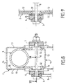
- la figure 8 est une coupe transversale analogue à la figure 1 d'un autre mode de réalisation de l'invention ;
- la figure 9 est une coupe suivant le plan XII-XII de la figure 8; et
Claims (6)
- Dispositif antirotation de corps de colonne de direction de véhicule automobile comportant un élément support (2) comportant deux ailes (17) et lié au châssis du véhicule et un corps (1), qui est maintenu en position par rapport à l'élément support au moyen d'un système de blocage (3), ledit dispositif antirotation comportant, pour le réglage de colonne considéré et dans une direction de réglage demandée, en profondeur ou en hauteur, des faces de liaison qui sont aménagées entre l'élément support (2) et le corps (1), lesdites faces de liaison ayant une direction sensiblement parallèle à la direction de réglage demandée, caractérisé en ce qu'il comporte :deux éléments intermédiaires (4 et 5) , chacun des deux éléments intermédiaires (4 et 5) étant disposé entre Tune des deux ailes (17) de l'élément support (2) et une face correspondante (13) du corps (1),chaque élément intermédiaire (4, 5) comportant sur une face interne (21) situé du côté du corps (1) un ensemble de deux faces de liaison (34) coopérant avec un ensemble de deux faces de liaison (35) agencées sur une portion latérale correspondante (12) d'un carré de renfort (11) appartenant au corps (1), lesdites faces de liaison (34, 35) étant orientées dans Tune des deux directions de réglage en profondeur ou en hauteur ;chaque élément intermédiaire (4, 5) comportant sur une face externe (22) situé du côté de l'élément support (2) un ensemble de deux faces de liaison (36) coopérant avec un ensemble de deux faces de liaison (37) agencées sur l'aile correspondante (17) de 1'élément support (2), lesdites faces de liaison (36, 37) étant orientées dans l'autre direction de réglage en hauteur ou en profondeur ;les faces de liaison (34) prévues sur la face interne (21) étant inclinées par rapport à ladite face interne (21) ; les faces de liaison (36) prévues sur la face externe (22) étant inclinées par rapport à ladite face externe (22) ; les faces de liaison (35) agencées sur la portion latérale (12) du corps (1) étant inclinées par rapport audit élément latéral (12) ; les faces de liaison (37) agencées sur l'aile (17) de l'élément support (2) étant inclinées par rapport à ladite aile (17) ;de manière à ce que les faces de liaison (34,35 - 36,37) coopèrent les unes avec les autres lors du blocage de la colonne de direction, afin d'assurer l'antirotation du corps de colonne, les faces de liaison (34, 35 - 36, 37) restant engagées les unes dans les autres en position débloquée.
- Dispositif antirotation de corps de colonne de direction de véhicule automobile comportant un élément support (2) lié au châssis du véhicule et un corps (1), qui est maintenu en position par rapport à l'élément support au moyen d'un système de blocage (3), ledit dispositif antirotation comportant, pour le réglage de colonne considéré et dans une direction de réglage demandée, en profondeur ou en hauteur, des faces de liaison qui sont aménagées entre l'élément support (2) et le corps (1), lesdites faces de liaison ayant une direction sensiblement parallèle à la direction de réglage demandée, l'élément support (2) étant en forme de U avec deux ailes (17), caractérisé en ce que chaque aile (17) comporte un ensemble de deux faces de liaison (26 ou 28) qui sont inclinées par rapport à ladite aile (17) et qui coopèrent avec un ensemble de deux faces de liaison (27 ou 29) qui sont agencées sur une portion latérale correspondante (12) d'un carré de renfort (11) appartenant au corps (1), et qui sont inclinées par rapport audit élément latéral (12) correspondant ; les faces de liaison (26,27 ou 28,29) étant orientées dans la direction du réglage en profondeur ou en hauteur demandée ;de manière à ce que les faces de liaison (26,27 - 28,29) coopèrent les unes avec les autres lors du blocage de la colonne de direction, afin d'assurer l'antirotation du corps de colonne, les faces de liaison (26,27 - 28,29) restant engagées les unes dans les autres en position débloquée.
- Dispositif antirotation selon la revendication 1 ou 2, caractérisé en ce que chaque groupe de deux faces de liaison (26,27 - 28,29 - 34,35 - 36,37) a les deux faces de liaison qui sont inclinées symétriquement l'une par rapport à l'autre.
- Dispositif antirotation selon l'une quelconque des revendications 1 à 3, caractérisé en ce qu'il comporte deux éléments de placage (6, 7) chaque élément de placage (6, 7) étant disposé sur un axe (8) du système de blocage (3) et à l'extérieur dune face externe (19) correspondante de l'élément support (2).
- Dispositif antirotation selon la revendication 4, caractérisé en ce que chaque élément de placage (6, 7) est disposé de manière à s'appliquer directement contre la face externe (19) correspondante de l'élément de support (2).
- Dispositif antirotation selon la revendication 1, caractérisé en ce que chaque élément intermédiaire (4, 5) comporte deux butées (24) intégrées à la face interne (21).
Applications Claiming Priority (2)
| Application Number | Priority Date | Filing Date | Title |
|---|---|---|---|
| FR9603010 | 1996-03-06 | ||
| FR9603010A FR2745777B1 (fr) | 1996-03-06 | 1996-03-06 | Dispositif antirotation de corps de colonne de direction de vehicule automobile |
Publications (2)
| Publication Number | Publication Date |
|---|---|
| EP0794103A1 EP0794103A1 (fr) | 1997-09-10 |
| EP0794103B1 true EP0794103B1 (fr) | 2002-10-02 |
Family
ID=9490041
Family Applications (1)
| Application Number | Title | Priority Date | Filing Date |
|---|---|---|---|
| EP97400420A Expired - Lifetime EP0794103B1 (fr) | 1996-03-06 | 1997-02-26 | Dispositif antirotation de corps de colonne de direction de véhicule automobile |
Country Status (6)
| Country | Link |
|---|---|
| US (1) | US5927152A (fr) |
| EP (1) | EP0794103B1 (fr) |
| BR (1) | BR9701206A (fr) |
| DE (1) | DE69715938T2 (fr) |
| ES (1) | ES2180005T3 (fr) |
| FR (1) | FR2745777B1 (fr) |
Families Citing this family (22)
| Publication number | Priority date | Publication date | Assignee | Title |
|---|---|---|---|---|
| DE19718031C1 (de) * | 1997-04-29 | 1998-08-13 | Supervis Ets | Spann- und Klemmvorrichtung |
| FR2768205B1 (fr) * | 1997-09-05 | 1999-10-29 | Lemforder Nacam Sa | Securite d'engagement a etrier d'un dispositif de maintien en position d'un systeme de serrage de deux elements |
| FR2780934B1 (fr) | 1998-07-13 | 2001-05-04 | Lemforder Nacam Sa | Dispositif de serrage a commande electrique pour un systeme de reglage en position d'un element par rapport a un autre element |
| FR2818226B1 (fr) * | 2000-12-18 | 2003-03-28 | Nacam | Dispositif d'encastrement d'un tube-corps de colonne de direction de vehicule automobile |
| FR2818602B1 (fr) * | 2000-12-26 | 2003-03-28 | Nacam | Dispositif de serrage d'un element reglable par rapport a un ensemble support |
| GB2375809B (en) * | 2001-05-23 | 2005-02-23 | Nsk Steering Sys Europ Ltd | Operating lever |
| DE10226769C1 (de) * | 2002-06-14 | 2003-11-13 | Nacam Deutschland Gmbh | Sicherheitsvorrichtung zum Arretieren eines verstellbaren Anschlussteils |
| FR2862037B1 (fr) * | 2003-11-12 | 2007-11-16 | Nacam France Sas | Serrage electrique d'une colonne de direction reglable de vehicule automobile |
| US7178832B2 (en) * | 2004-01-06 | 2007-02-20 | Delphi Technologies, Inc. | Telescoping steering column assembly with brake |
| US7516985B2 (en) * | 2004-03-11 | 2009-04-14 | Delphi Technologies, Inc. | Multi piece bearing for telescoping steering column assembly |
| US20050200111A1 (en) * | 2004-03-11 | 2005-09-15 | Cymbal William D. | Multi piece bearing for telescoping steering column assembly |
| FR2880607B1 (fr) | 2005-01-12 | 2007-03-30 | Fuji Autotech France Sas Soc P | Dispositif de blocage en position d'une colonne de direction reglable de vehicule automobile, ensemble comprenant un tel dispositif, et vehicule automobile comprenant un tel ensemble |
| US7367589B2 (en) * | 2005-07-15 | 2008-05-06 | Chrysler Llc | Collapsible steering assembly with a stationary reaction surface |
| DE102006007553B3 (de) | 2006-02-16 | 2007-05-16 | Thyssenkrupp Presta Ag | Verstellbare Lenksäule für ein Kraftfahrzeug |
| US7874228B2 (en) * | 2008-02-14 | 2011-01-25 | Nexteer (Beijing) Technology Co., Ltd. | Non-translating telescopic rake pivot for steering column assembly |
| DE102011056674B3 (de) | 2011-10-19 | 2012-12-06 | Thyssenkrupp Presta Aktiengesellschaft | Lenksäule für ein Kraftfahrzeug |
| DE102011054598B3 (de) | 2011-10-19 | 2013-01-17 | Thyssenkrupp Presta Ag | Lenkspindellagereinheit zur drehbaren Lagerung einer Lenkspindel |
| DE102011054606B3 (de) | 2011-10-19 | 2013-02-28 | Thyssenkrupp Presta Aktiengesellschaft | Lenkspindellagereinheit zur drehbaren Lagerung einer Lenkspindel |
| DE102011054597A1 (de) | 2011-10-19 | 2013-04-25 | Thyssenkrupp Presta Aktiengesellschaft | Lenkspindellagereinheit |
| US10086864B2 (en) | 2014-04-08 | 2018-10-02 | Nsk Ltd | Steering wheel position-adjustment device |
| US9932063B2 (en) | 2015-05-26 | 2018-04-03 | Toyota Motor Engineering & Manufacturing North America, Inc. | Vehicles and vehicle systems for restricting rotation of a vehicle steering system |
| US9937952B2 (en) | 2015-05-26 | 2018-04-10 | Toyota Motor Engineering & Manufacturing North America, Inc. | Vehicles and vehicle systems for restricting rotation of a vehicle steering system |
Citations (1)
| Publication number | Priority date | Publication date | Assignee | Title |
|---|---|---|---|---|
| EP0408847A1 (fr) * | 1989-06-24 | 1991-01-23 | Bayerische Motoren Werke Aktiengesellschaft | Dispositif pour ajuster en longueur et en hauteur la colonne de direction d'une voiture |
Family Cites Families (11)
| Publication number | Priority date | Publication date | Assignee | Title |
|---|---|---|---|---|
| US4046024A (en) * | 1976-04-26 | 1977-09-06 | Eaton Corporation | Adjustable steering column support |
| GB2113629B (en) * | 1982-01-15 | 1985-07-17 | Ford Motor Co | Mounting for an adjustable steering column |
| US5117707A (en) * | 1990-02-23 | 1992-06-02 | Fuji Kiko Company, Limited | Tilting steering column |
| DE4034710C2 (de) * | 1990-11-01 | 1994-11-17 | Daimler Benz Ag | Lagerung für ein Mantelrohr einer Lenksäule eines Kraftfahrzeugs |
| GB2259132A (en) * | 1991-08-27 | 1993-03-03 | Torrington Co | Locking device for adjustable steering column. |
| FR2696403B1 (fr) * | 1992-10-06 | 1995-01-06 | Ecia Equip Composants Ind Auto | Dispositif de blocage en position d'une colonne de direction réglable par exemple de véhicule automobile et ensemble de colonne comportant un tel dispositif. |
| GB2281539A (en) * | 1993-09-01 | 1995-03-08 | Torrington Co | Adjustable vehicle steering column assembly |
| US5655413A (en) * | 1994-06-22 | 1997-08-12 | The Torrington Company | Antifriction element for use between relatively sliding components of an adjustable steering column |
| US5722299A (en) * | 1994-06-30 | 1998-03-03 | Fuji Kiko Co., Ltd. | Adjustable steering column assembly for a vehicle |
| FR2737172B1 (fr) * | 1995-07-26 | 1997-10-10 | Nacam | Systeme de guidage et de verrouillage pour colonne de direction de vehicules automobile |
| GB2310708B (en) * | 1996-02-27 | 1999-09-15 | Delphi France Automotive Sys | Clamping device for a steering column |
-
1996
- 1996-03-06 FR FR9603010A patent/FR2745777B1/fr not_active Expired - Fee Related
-
1997
- 1997-02-26 DE DE69715938T patent/DE69715938T2/de not_active Expired - Fee Related
- 1997-02-26 ES ES97400420T patent/ES2180005T3/es not_active Expired - Lifetime
- 1997-02-26 EP EP97400420A patent/EP0794103B1/fr not_active Expired - Lifetime
- 1997-03-05 US US08/811,944 patent/US5927152A/en not_active Expired - Fee Related
- 1997-03-06 BR BR9701206A patent/BR9701206A/pt not_active IP Right Cessation
Patent Citations (1)
| Publication number | Priority date | Publication date | Assignee | Title |
|---|---|---|---|---|
| EP0408847A1 (fr) * | 1989-06-24 | 1991-01-23 | Bayerische Motoren Werke Aktiengesellschaft | Dispositif pour ajuster en longueur et en hauteur la colonne de direction d'une voiture |
Also Published As
| Publication number | Publication date |
|---|---|
| DE69715938T2 (de) | 2003-08-14 |
| FR2745777B1 (fr) | 1998-04-30 |
| FR2745777A1 (fr) | 1997-09-12 |
| US5927152A (en) | 1999-07-27 |
| EP0794103A1 (fr) | 1997-09-10 |
| BR9701206A (pt) | 1998-11-10 |
| ES2180005T3 (es) | 2003-02-01 |
| DE69715938D1 (de) | 2002-11-07 |
Similar Documents
| Publication | Publication Date | Title |
|---|---|---|
| EP0794103A1 (fr) | Dispositif antirotation de corps de colonne de direction de véhicule automobile | |
| EP1345804B1 (fr) | Dispositif de serrage d'un element reglable par rapport a un ensemble support | |
| EP0755842B1 (fr) | Système de guidage et de verrouillage pour colonne de direction de véhicule automobile | |
| EP0755844B1 (fr) | Dispositif d'absorption d'énergie et de guidage pour colonne de direction de véhicule automobile | |
| FR2768205A1 (fr) | Securite d'engagement a etrier d'un dispositif de maintien en position d'un systeme de serrage de deux elements | |
| EP0805092B1 (fr) | Dispositif de rétroaction actif, lors d'un choc, d'une colonne de direction de véhicule automobile | |
| EP0805093B1 (fr) | Dispositif de positionnement, lors d'un choc, d'une colonne de direction de véhicule automobile | |
| EP0634314B1 (fr) | Ensemble de colonne de direction rétractable axialement en cas de choc, notamment pour véhicule automobile | |
| EP2382364A1 (fr) | Systeme d'articulation d'un capot de vehicule automobile et capot associe | |
| FR2768203A1 (fr) | Securite d'engagement a basculement d'un dispositif de maintien en position d'un systeme de serrage de deux elements | |
| EP0800978B1 (fr) | Ensemble de colonne de direction à absorption d'énergie de choc, notamment pour véhicule automobile | |
| FR2881707A1 (fr) | Dispositif d'absorption instantanee d'energie d'une colonne de direction de vehicule automobile | |
| FR2701913A1 (fr) | Ensemble de sécurité pour dispositif de liaison séparable, notamment pour colonne de direction de véhicule automobile. | |
| EP0559570A1 (fr) | Accouplement élastique | |
| FR2653730A1 (fr) | Colonne de direction de securite perfectionnee pour vehicule automobile. | |
| EP0503993B1 (fr) | Dispositif de fixation d'un levier de commande de boîte de vitesses à proximité d'une planche de bord de véhicule | |
| EP0459849B1 (fr) | Pare-chocs à fixation réglable pour véhicule automobile | |
| FR3135949A1 (fr) | colonne de direction pour véhicule automobile | |
| EP0667277B1 (fr) | Système anti-remontée de l'axe volant d'une colonne de direction | |
| EP0734937B1 (fr) | Système de verrouillage de sécurité pour un ensemble de colonne de direction réglable en position, notamment de véhicule automobile | |
| FR3135950A1 (fr) | colonne de direction pour véhicule automobile | |
| FR3137636A1 (fr) | Doublure interne pour capot de véhicule automobile, capot de véhicule automobile comportant une telle doublure interne et véhicule automobile comportant un tel capot | |
| WO2021148742A1 (fr) | Véhicule automobile disposant d'un moyen de dégagement de la roue avant en cas de choc frontal | |
| FR3156415A1 (fr) | Ensemble de direction pour véhicule automobile | |
| FR3044599A1 (fr) | "agencement pour l'articulation d'un essieu sur un chassis de vehicule automobile" |
Legal Events
| Date | Code | Title | Description |
|---|---|---|---|
| PUAI | Public reference made under article 153(3) epc to a published international application that has entered the european phase |
Free format text: ORIGINAL CODE: 0009012 |
|
| AK | Designated contracting states |
Kind code of ref document: A1 Designated state(s): DE ES FR GB IT |
|
| 17P | Request for examination filed |
Effective date: 19970913 |
|
| 17Q | First examination report despatched |
Effective date: 19991014 |
|
| GRAG | Despatch of communication of intention to grant |
Free format text: ORIGINAL CODE: EPIDOS AGRA |
|
| GRAG | Despatch of communication of intention to grant |
Free format text: ORIGINAL CODE: EPIDOS AGRA |
|
| GRAH | Despatch of communication of intention to grant a patent |
Free format text: ORIGINAL CODE: EPIDOS IGRA |
|
| RAP1 | Party data changed (applicant data changed or rights of an application transferred) |
Owner name: NACAM FRANCE SA |
|
| GRAH | Despatch of communication of intention to grant a patent |
Free format text: ORIGINAL CODE: EPIDOS IGRA |
|
| GRAA | (expected) grant |
Free format text: ORIGINAL CODE: 0009210 |
|
| AK | Designated contracting states |
Kind code of ref document: B1 Designated state(s): DE ES FR GB IT |
|
| REG | Reference to a national code |
Ref country code: GB Ref legal event code: FG4D Free format text: NOT ENGLISH |
|
| REF | Corresponds to: |
Ref document number: 69715938 Country of ref document: DE Date of ref document: 20021107 |
|
| GBT | Gb: translation of ep patent filed (gb section 77(6)(a)/1977) |
Effective date: 20021104 |
|
| REG | Reference to a national code |
Ref country code: ES Ref legal event code: FG2A Ref document number: 2180005 Country of ref document: ES Kind code of ref document: T3 |
|
| PLBE | No opposition filed within time limit |
Free format text: ORIGINAL CODE: 0009261 |
|
| STAA | Information on the status of an ep patent application or granted ep patent |
Free format text: STATUS: NO OPPOSITION FILED WITHIN TIME LIMIT |
|
| 26N | No opposition filed |
Effective date: 20030703 |
|
| PGFP | Annual fee paid to national office [announced via postgrant information from national office to epo] |
Ref country code: GB Payment date: 20040130 Year of fee payment: 8 |
|
| PGFP | Annual fee paid to national office [announced via postgrant information from national office to epo] |
Ref country code: DE Payment date: 20040203 Year of fee payment: 8 |
|
| PGFP | Annual fee paid to national office [announced via postgrant information from national office to epo] |
Ref country code: ES Payment date: 20040217 Year of fee payment: 8 |
|
| PGFP | Annual fee paid to national office [announced via postgrant information from national office to epo] |
Ref country code: FR Payment date: 20050120 Year of fee payment: 9 |
|
| PG25 | Lapsed in a contracting state [announced via postgrant information from national office to epo] |
Ref country code: IT Free format text: LAPSE BECAUSE OF NON-PAYMENT OF DUE FEES Effective date: 20050226 Ref country code: GB Free format text: LAPSE BECAUSE OF NON-PAYMENT OF DUE FEES Effective date: 20050226 |
|
| PG25 | Lapsed in a contracting state [announced via postgrant information from national office to epo] |
Ref country code: ES Free format text: LAPSE BECAUSE OF NON-PAYMENT OF DUE FEES Effective date: 20050228 |
|
| PG25 | Lapsed in a contracting state [announced via postgrant information from national office to epo] |
Ref country code: DE Free format text: LAPSE BECAUSE OF NON-PAYMENT OF DUE FEES Effective date: 20050901 |
|
| GBPC | Gb: european patent ceased through non-payment of renewal fee |
Effective date: 20050226 |
|
| REG | Reference to a national code |
Ref country code: ES Ref legal event code: FD2A Effective date: 20050228 |
|
| REG | Reference to a national code |
Ref country code: FR Ref legal event code: ST Effective date: 20061031 |
|
| PG25 | Lapsed in a contracting state [announced via postgrant information from national office to epo] |
Ref country code: FR Free format text: LAPSE BECAUSE OF NON-PAYMENT OF DUE FEES Effective date: 20060228 |