US4046024A - Adjustable steering column support - Google Patents
Adjustable steering column support Download PDFInfo
- Publication number
- US4046024A US4046024A US05/679,947 US67994776A US4046024A US 4046024 A US4046024 A US 4046024A US 67994776 A US67994776 A US 67994776A US 4046024 A US4046024 A US 4046024A
- Authority
- US
- United States
- Prior art keywords
- frictional
- frame assembly
- longitudinal axis
- movable member
- movement
- Prior art date
- Legal status (The legal status is an assumption and is not a legal conclusion. Google has not performed a legal analysis and makes no representation as to the accuracy of the status listed.)
- Expired - Lifetime
Links
Images


Classifications
-
- B—PERFORMING OPERATIONS; TRANSPORTING
- B62—LAND VEHICLES FOR TRAVELLING OTHERWISE THAN ON RAILS
- B62D—MOTOR VEHICLES; TRAILERS
- B62D1/00—Steering controls, i.e. means for initiating a change of direction of the vehicle
- B62D1/02—Steering controls, i.e. means for initiating a change of direction of the vehicle vehicle-mounted
- B62D1/16—Steering columns
- B62D1/18—Steering columns yieldable or adjustable, e.g. tiltable
- B62D1/184—Mechanisms for locking columns at selected positions
-
- Y—GENERAL TAGGING OF NEW TECHNOLOGICAL DEVELOPMENTS; GENERAL TAGGING OF CROSS-SECTIONAL TECHNOLOGIES SPANNING OVER SEVERAL SECTIONS OF THE IPC; TECHNICAL SUBJECTS COVERED BY FORMER USPC CROSS-REFERENCE ART COLLECTIONS [XRACs] AND DIGESTS
- Y10—TECHNICAL SUBJECTS COVERED BY FORMER USPC
- Y10T—TECHNICAL SUBJECTS COVERED BY FORMER US CLASSIFICATION
- Y10T74/00—Machine element or mechanism
- Y10T74/20—Control lever and linkage systems
- Y10T74/20576—Elements
- Y10T74/20636—Detents
- Y10T74/2066—Friction
Definitions
- the present invention relates to adjustable steering column mechanisms, and more particularly, to such mechanisms which permit both telescoping and tilting of the column and steering wheel.
- Adjustable steering columns have become quite popular, especially for commercial vehicles, such as trucks, which the operator may drive continually over a long period of time.
- the ability to adjust the steering column and steering wheel greatly enhances the comfort of the driver and compensates for the varying sizes of drivers and the varying seat positions utilized by different drivers.
- Prior art adjustable steering column mechanisms have generally provided either a telescopic movement of the column, providing linear movement of the steering wheel toward and away from the driver, or a tilting movement of the column, providing pivotal movement of the steering wheel about an axis perpendicular to the steering column, although a few relatively complex mechanisms have provided for both telescopic and tilting movement.
- a telescopic movement of the column providing linear movement of the steering wheel toward and away from the driver
- a tilting movement of the column providing pivotal movement of the steering wheel about an axis perpendicular to the steering column
- Adjustable steering column mechanisms have generally been of either the detent type or the friction type.
- a detent mechanism is operable to engage a movable member having a plurality of holes or slots, each of which corresponds to a separate, discreet position of the steering column.
- Another disadvantage of the detent type of mechanism is that by its very nature, the manufacturing tolerances of the mating and engaging parts must be held very close in order to avoid looseness and an undesirable, noisy rattling of the parts.
- a pair of relatively movable members such as an inner tube and an outer tube
- the friction type mechanism generally has the advantage of being infinitely adjustable within the given range, but generally has the disadvantage of insufficient locking force, especially when the vehicle operator swings himself into the cab while holding onto the steering wheel.
- an object of the present invention to provide an adjustable steering column mechanism which is adapted for both telescoping and tilting movement of the column simultaneously, and in response to the movement of only one control handle.
- telescoping is used to denote linear movement of the entire steering column toward and away from the driver.
- an improved apparatus for adjustably mounting the steering column in a vehicle comprising a frame assembly defining a longitudinal axis and a tubular member rigidly mounted to the steering column and associated with the frame assembly for axial and rotational movement relative thereto.
- the tubular member includes a frictional surface and first and second frictional members are oppositely disposed about the longitudinal axis of the frame assembly and are disposed adjacent the frictional surface of the tubular member.
- the frame assembly includes means for guiding the movement of the first and second frictional members relative to the frame assembly.
- a clamping means is pivotally mounted to the tubular member for movement therewith and includes a means for actuating the clamping means, the actuating means being movable between an operative condition and a neutral condition.
- the clamping means exerts a force biasing each of the first and second frictional members into frictional engagement with the adjacent frictional surface of the tubular member and with the guiding means.
- the clamping means releases the biasing force on the first and second frictional members and permits simultaneous axial and rotational movement of the tubular member relative to the frame assembly.
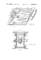
- FIG. 1 is a side elevation of the adjustable steering column mechanism of the present invention, illustrating two substantially different positions of the column and steering wheel.
- FIG. 2 is an enlarged, side elevation of the mechanism of the present invention.
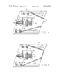
- FIG. 3 is a transverse cross section taken on line 3--3 of FIG. 2.
- FIG. 4 is a longitudinal cross section taken on line 4--4 of FIG. 3.
- FIG. 4A is a fragmentary view, similar to FIG. 4, but with the mechanism in the unlocked position.
- FIG. 5 is a longitudinal cross section, similar to FIG. 4, with the mechanism again locked, but positioned to have the steering column in a different position.
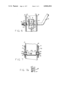
- FIG. 6 is a fragmentary cross section taken on line 6--6 of FIG. 4.
- FIG. 7 is a fragmentary cross section taken on line 7--7 of FIG. 2.
- FIG. 7A is an elevation of the anti-rotation insert shown in cross section in FIG. 7.
- FIGS. 8 and 8A are cross sections taken on line 8--8 of FIG. 3, corresponding to the positions shown in FIGS. 4 and 4A, respectively.
- FIG. 1 illustrates semi-schematically the installation of the mechanism of the present invention.
- the adjustable steering column mechanism generally designated 11, may be installed by means of a mounting angle A and a mounting bracket B which are well-known and form no part of the present invention.
- a steering wheel W and a steering column S which may be rigidly mounted to the movable portion of the mechanism 11 by means of a clamping assembly C.
- an alternative position for the steering wheel W and steering column S which may be moved to any desired position by rotating a handle 13 to unlock the mechanism 11 as will be described in greater detail subsequently.
- the mechanism 11 includes a pair of side frames 15 which are rigidly mounted within the vehicle by means of the mounting angle A and the mounting bracket B. Disposed between the side frames 15 is an inner tube 17 which, as may best be seen in FIG. 2, comprises the movable part of the mechanism 11 and is mounted to the steering column S by the clamping assembly C.
- the inner tube 17 is preferably formed of a pair of mating, stamped portions 19 welded into the tubular member whose profile is best seen in FIG. 3.
- Each of the side frames 15 defines a longitudinally-extending large central slot 21, a longitudinally-extending upper slot 23, and a longitudinally-extending lower slot 25.
- the handle 13 includes a cylindrical portion 27, oriented transversely, and extending through the central slots 21 and free to move longitudinally therein when the mechanism 11 is unlocked (in the neutral condition).
- Each of the side panels 19 of the inner tube 17 defines a circular opening 29 through which the cylindrical portion 27 extends, such that the inner tube 17 is rotatable, relative to the side frames 15 and relative to the cylindrical portion 27, about the axis of the cylindrical portion 27.
- the tilting movement of the steering column S occurs when the inner tube 17 is rotated about the cylindrical portion 27, and the telescoping movement of the steering column S occurs when the inner tube 17 and cylindrical portion 27 move longitudinally relative to the central slot 21.
- a threaded portion 31 At the end of the cylindrical portion 27 (see FIGS. 3 and 6) is a threaded portion 31, and in threaded engagement therewith is a nut 33, with a washer 35 disposed between the nut 33 and the adjacent side frame 15.
- the cylindrical portion 27 extends through a centrally-disposed actuating mechanism 37 which, as may best be seen in FIG. 6, includes a generally U-shaped locking channel 39, and disposed between the side walls of the locking channel 39 is an actuating bar 41.
- the actuating bar 41 is fixed relative to the cylindrical portion 27 by means of a bolt 43 and a nut 45 (see FIGS. 3 and 4), and the actuating bar 41 is pivotally mounted relative to the locking channel 39 by means of a pin 47.
- a stud member including a head portion 49, which is preferably welded to the forward wall of the locking channel 39, and a stud portion 51 extending forwardly therefrom.
- the stud portion 51 extends through a longitudinal bore defined by a generally cylindrical pull bar 53 which, as may best be seen in FIG. 7, is oriented transversely of the mechanism 11 and is approximately as long as the inside distance between the side frames 15.
- the pull bar 53 has a generally flat, forward face 55 against which is seated a nut 57, in threaded engagement with a forward, threaded portion 59 of the stud portion 51.
- the pull bar 53 includes a pair of oppositely-disposed, generally cylindrical end portions 61, each of which is preferably coaxial with the pull bar 53.
- Each of the end portions 61 extends through and is freely rotatable within a bore 63 defined by a generally T-shaped anti-rotation insert 65.
- the insert 65 as is best seen in FIGS. 2, 7 and 7A, includes a generally rectangular horizontal portion 67 and a generally rectangular, vertical portion 69.
- the horizontal portion 67 is sized to slide freely within the central slot 21, without being able to cock within the slot 21.
- Disposed on the outside of each of the side frames 15 is a slide adjuster 71 (see FIG. 2), each of which defines an elongated, generally rectangular slot 73, and within the slot 73 is disposed the vertical portion 69 of the insert 65.
- the vertical portion 69 is sized to slide freely within the slot 73, but does not permit relative angular movement therebetween for reasons which will be discussed subsequently.
- the portions 61 are shouldered and threaded beyond the insert 65 to receive nuts 74 which retain the slide adjuster 71 in position.
- a pair of generally heart-shaped upper slides 75 and a pair of generally heart-shaped lower slides 77 Extending transversely through the upper slots 23 and through the upper slides 75 is a pin 79, at each end of which a fastener 81 (shown only in FIG. 3) retains the slides 75 on the pin 79.
- a pin 83 Extending transversely through the lower slots 25 and through the lower slides 77 is a pin 83, at each end of which one of the fasteners 81 retains the slides 77 on the pin 83.
- each of the upper slides 75 includes a cylindrical projection 85 which engages the respective upper slot 23 to permit only longitudinal movement of the upper slides 75 and prevent rotational movement thereof.
- each of the lower slides 77 includes a cylindrical projection 87 which engages the respective lower slot 25 to permit only longitudinal movement of the lower slides 77 and prevent rotational movement thereof.
- the slide adjuster 71 includes an upper adjuster surface 89 and lower adjuster surface 91.
- the upper slide 75 includes a slide surface 93 which is in sliding engagement with the adjuster surface 89
- the lower slide 77 includes a slide surface 94, in sliding engagement with the lower adjuster surface 91.
- the forward end of the inner tube 17 comprises a friction surface 95.
- each of the side walls of the locking channel 39 includes a generally V-shaped cut-out portion 97 and an angled surface 99. Therefore, when the cylindrical portion 27 is rotated from the locked (actuated) position shown in FIG. 8 to the unlocked (neutral) position shown in FIG.
- the cylindrical portion 27 is spaced from the angled surface 99 which effectively increases the center-to-center distance between the pull bar 53 and the cylindrical portion 27. Because the longitudinal position of the slide adjusters 71 is controlled by the position of the anti-rotation inserts 65 which are mounted on end portions 61, it will be appreciated that turning the cylindrical portion 27 increases the longitudinal separation between the cylindrical portion 27 and the slide adjusters 71.
- the upper and lower adjuster surfaces 89 and 91 and the slide surfaces 93 and 94 should all be oriented at substantially 45° relative to the longitudinal axis of the mechanism (or to the vertical axis defined by the vertical slot 73).
- the slots 23 and 25 which guide the longitudinal movement of the slides 75 and 77, respectively, must be oriented substantially parallel to the longitudinally extending central slot 21 in order to prevent either binding or excessive looseness as the slides and the slide adjuster are moved to various positions along the slots 21, 23 and 25.
- the upper slots 23 and the lower slots 25 are disposed about as far from the central slot 21 as is possible in order that the frictional force applied against friction surface 95 will have a long enough lever arm (i.e., the distance from the pivot point or axis of cylindrical portion 27) to provide a sufficient holding torque acting on the inner tube 17.
- the present invention has been described in connection with one specific embodiment, it will be understood that many modifications and alterations in this specific hardware will fall within the contemplated scope of the invention.
- the fixed portion of the mechanism i.e., the side frames 15
- the movable portion i.e., the inner tube 17.
- the mechanism provides for both telescopic (longitudinal) and tilting (rotational) movement of the inner tube 17 and steering wheel W, while at the same time, taking advantage of the infinitely adjustable feature of the friction type mechanisms and utilizing friction in a manner which more or less provides a positive-action type of locking.
Landscapes
- Engineering & Computer Science (AREA)
- Chemical & Material Sciences (AREA)
- Combustion & Propulsion (AREA)
- Transportation (AREA)
- Mechanical Engineering (AREA)
- Steering Controls (AREA)
Abstract
Description
Claims (21)
Priority Applications (1)
| Application Number | Priority Date | Filing Date | Title |
|---|---|---|---|
| US05/679,947 US4046024A (en) | 1976-04-26 | 1976-04-26 | Adjustable steering column support |
Applications Claiming Priority (1)
| Application Number | Priority Date | Filing Date | Title |
|---|---|---|---|
| US05/679,947 US4046024A (en) | 1976-04-26 | 1976-04-26 | Adjustable steering column support |
Publications (1)
| Publication Number | Publication Date |
|---|---|
| US4046024A true US4046024A (en) | 1977-09-06 |
Family
ID=24729037
Family Applications (1)
| Application Number | Title | Priority Date | Filing Date |
|---|---|---|---|
| US05/679,947 Expired - Lifetime US4046024A (en) | 1976-04-26 | 1976-04-26 | Adjustable steering column support |
Country Status (1)
| Country | Link |
|---|---|
| US (1) | US4046024A (en) |
Cited By (15)
| Publication number | Priority date | Publication date | Assignee | Title |
|---|---|---|---|---|
| FR2440303A1 (en) * | 1978-10-31 | 1980-05-30 | Fenwick Manutention Ste Indle | Steering wheel adjustment for small delivery truck - has cranked parallelogram assembly and air spring to adjust rake and height |
| EP0015705A1 (en) * | 1979-02-28 | 1980-09-17 | Lansing Bagnall Limited | Vehicle steering apparatus |
| US4507982A (en) * | 1981-02-13 | 1985-04-02 | Ford Motor Company | Steering column assembly |
| US4537089A (en) * | 1983-01-14 | 1985-08-27 | J. I. Case Company | Steering wheel |
| US4682787A (en) * | 1986-01-21 | 1987-07-28 | Deere & Company | Steering unit and control lever console for a vehicle |
| US5131287A (en) * | 1988-10-31 | 1992-07-21 | Ffv Autotech Aktiebolag | Steering wheel rod with sliding and tilting movements |
| US5927152A (en) * | 1996-03-06 | 1999-07-27 | Lemforder Nacam | Device for preventing rotation of steering column body of an automobile vehicle |
| US20050242562A1 (en) * | 2004-04-30 | 2005-11-03 | Delphi Technologies, Inc. | Horizontal hybrid collapsing steering column |
| WO2006108631A1 (en) * | 2005-04-12 | 2006-10-19 | Zf Lenksysteme Gmbh | Arrangement of a steering column |
| US20060266152A1 (en) * | 2005-05-26 | 2006-11-30 | Armstrong Ray G | One lever tilt and telescope mechanism |
| US7278660B2 (en) | 2004-10-07 | 2007-10-09 | Delphi Technologies, Inc. | Rake and telescope column lock safety function |
| US20090250916A1 (en) * | 2008-04-07 | 2009-10-08 | Delphi Technologies, Inc. | Adjustable steering column assembly for a vehicle |
| US20100218637A1 (en) * | 2007-11-13 | 2010-09-02 | Renault Trucks | Device for adjusting the position of a steering column |
| US7942076B2 (en) | 2008-02-14 | 2011-05-17 | Nexteer (Beijing) Technology Co., Ltd. | Adjustable steering column assembly |
| WO2014124224A1 (en) * | 2013-02-08 | 2014-08-14 | ZF Steering Systems, LLC | Adjustable steering column |
Citations (4)
| Publication number | Priority date | Publication date | Assignee | Title |
|---|---|---|---|---|
| US3724290A (en) * | 1971-09-13 | 1973-04-03 | Liner U Inc | Adjustable tilt steering device |
| US3803939A (en) * | 1972-12-01 | 1974-04-16 | Chrysler Corp | Adjustable tiltable steering column |
| US3977692A (en) * | 1975-03-20 | 1976-08-31 | The Scott & Fetzer Company | Extensible support structure |
| US3978740A (en) * | 1975-06-02 | 1976-09-07 | International Harvester Company | Adjustable steering column |
-
1976
- 1976-04-26 US US05/679,947 patent/US4046024A/en not_active Expired - Lifetime
Patent Citations (4)
| Publication number | Priority date | Publication date | Assignee | Title |
|---|---|---|---|---|
| US3724290A (en) * | 1971-09-13 | 1973-04-03 | Liner U Inc | Adjustable tilt steering device |
| US3803939A (en) * | 1972-12-01 | 1974-04-16 | Chrysler Corp | Adjustable tiltable steering column |
| US3977692A (en) * | 1975-03-20 | 1976-08-31 | The Scott & Fetzer Company | Extensible support structure |
| US3978740A (en) * | 1975-06-02 | 1976-09-07 | International Harvester Company | Adjustable steering column |
Cited By (22)
| Publication number | Priority date | Publication date | Assignee | Title |
|---|---|---|---|---|
| FR2440303A1 (en) * | 1978-10-31 | 1980-05-30 | Fenwick Manutention Ste Indle | Steering wheel adjustment for small delivery truck - has cranked parallelogram assembly and air spring to adjust rake and height |
| EP0015705A1 (en) * | 1979-02-28 | 1980-09-17 | Lansing Bagnall Limited | Vehicle steering apparatus |
| US4507982A (en) * | 1981-02-13 | 1985-04-02 | Ford Motor Company | Steering column assembly |
| US4537089A (en) * | 1983-01-14 | 1985-08-27 | J. I. Case Company | Steering wheel |
| US4682787A (en) * | 1986-01-21 | 1987-07-28 | Deere & Company | Steering unit and control lever console for a vehicle |
| US5131287A (en) * | 1988-10-31 | 1992-07-21 | Ffv Autotech Aktiebolag | Steering wheel rod with sliding and tilting movements |
| US5927152A (en) * | 1996-03-06 | 1999-07-27 | Lemforder Nacam | Device for preventing rotation of steering column body of an automobile vehicle |
| US20050242562A1 (en) * | 2004-04-30 | 2005-11-03 | Delphi Technologies, Inc. | Horizontal hybrid collapsing steering column |
| US8596684B2 (en) | 2004-04-30 | 2013-12-03 | Steering Solutions Ip Holding Corporation | Horizontal hybrid collapsing steering column |
| US7942446B2 (en) * | 2004-04-30 | 2011-05-17 | Nexteer (Beijing) Technology Co., Ltd. | Horizontal hybrid collapsing steering column |
| US7278660B2 (en) | 2004-10-07 | 2007-10-09 | Delphi Technologies, Inc. | Rake and telescope column lock safety function |
| WO2006108631A1 (en) * | 2005-04-12 | 2006-10-19 | Zf Lenksysteme Gmbh | Arrangement of a steering column |
| US7503234B2 (en) * | 2005-05-26 | 2009-03-17 | Delphi Technologies, Inc. | One lever tilt and telescope mechanism |
| US20060266152A1 (en) * | 2005-05-26 | 2006-11-30 | Armstrong Ray G | One lever tilt and telescope mechanism |
| US20100218637A1 (en) * | 2007-11-13 | 2010-09-02 | Renault Trucks | Device for adjusting the position of a steering column |
| US8726757B2 (en) * | 2007-11-13 | 2014-05-20 | Renault Trucks | Device for adjusting the position of a steering column |
| US7942076B2 (en) | 2008-02-14 | 2011-05-17 | Nexteer (Beijing) Technology Co., Ltd. | Adjustable steering column assembly |
| US20110179900A1 (en) * | 2008-02-14 | 2011-07-28 | Olgren Leland N | Adjustable steering column assembly |
| US8297145B2 (en) | 2008-02-14 | 2012-10-30 | Steering Solutions Ip Holding Corporation | Adjustable steering column assembly |
| US20090250916A1 (en) * | 2008-04-07 | 2009-10-08 | Delphi Technologies, Inc. | Adjustable steering column assembly for a vehicle |
| US7914043B2 (en) | 2008-04-07 | 2011-03-29 | Nexteer (Beijing) Technology Co., Ltd. | Adjustable steering column assembly for a vehicle |
| WO2014124224A1 (en) * | 2013-02-08 | 2014-08-14 | ZF Steering Systems, LLC | Adjustable steering column |
Similar Documents
| Publication | Publication Date | Title |
|---|---|---|
| US4046024A (en) | Adjustable steering column support | |
| US5522488A (en) | Adjusting apparatus for adjusting an automobile seat | |
| US4018101A (en) | Positioning device for adjustable steering columns | |
| US5213003A (en) | Locking device for an adjustable steering column assembly | |
| JPH0639230B2 (en) | Vehicle seat adjustment device | |
| US6254188B1 (en) | Seat track with cam actuated locking device | |
| US4075903A (en) | Adjustable steering column | |
| JPS5925701B2 (en) | Adjustable steering wheel and transmission locking device | |
| US6378928B1 (en) | Pivoting actuator for seat track assembly | |
| US5537890A (en) | Motor vehicle steering column | |
| US1987431A (en) | Adjustable seat for vehicles | |
| US4244236A (en) | Tilt steering column mechanism | |
| US3078946A (en) | Movable steering column | |
| US4424721A (en) | Adjustable steering column | |
| US3545290A (en) | Remotely controlled vehicle mirror | |
| JP2582995Y2 (en) | Rotating seat for vehicles | |
| US2188281A (en) | Brake control mechanism | |
| US6428088B1 (en) | Locking sunshade system | |
| US3402511A (en) | Sun roof control handle | |
| GB2106172A (en) | Seat back adjustment mechanism | |
| JPS63137051A (en) | Locking mechanism for seat slide | |
| GB2273971A (en) | Adjustable steering column mechanism. | |
| JPH0367779A (en) | Tilt steering device | |
| US20060144183A1 (en) | Steering column tilt adjusting system | |
| JP2582817Y2 (en) | Vehicle seat truck |
Legal Events
| Date | Code | Title | Description |
|---|---|---|---|
| AS | Assignment |
Owner name: SIGNET SYSTEMS, INC., HARRODSBURG, KY., Free format text: ASSIGNMENT OF ASSIGNORS INTEREST.;ASSIGNOR:EATON CORPORATION;REEL/FRAME:004162/0483 Effective date: 19830630 Owner name: BA COMMERCIAL CORPORATION, 1621 CEDAR CREST BLVD., Free format text: SECURITY INTEREST;ASSIGNOR:SIGNET SYSTEMS, INC.;REEL/FRAME:004162/0476 Effective date: 19830630 |
|
| AS | Assignment |
Owner name: BA COMMERCIAL CORPORATION, 1621 CEDAR CREST BLVD., Free format text: SECURITY INTEREST;ASSIGNOR:SIGNET SYSTEMS, INC.;REEL/FRAME:004219/0216 Effective date: 19830630 |
|
| AS | Assignment |
Owner name: SIGNET SYSTEMS, INC., TAPP ROAD, P.O. BOX 367 HARR Free format text: RELEASED BY SECURED PARTY;ASSIGNOR:BANCAMERICA COMMERCIAL CORPORATION;REEL/FRAME:004302/0856 Effective date: 19840809 Owner name: CONNECTICUT BANK AND TRUST COMPANY, N.A. THE, 900 Free format text: SECURITY INTEREST;ASSIGNOR:SIGNET SYSTEMS, INC.;REEL/FRAME:004302/0861 Effective date: 19840906 |
|
| STCF | Information on status: patent grant |
Free format text: PATENTED FILE - (OLD CASE ADDED FOR FILE TRACKING PURPOSES) |
|
| AS | Assignment |
Owner name: SIGNET SYSTEMS, INC., 1531 POMONA RD., CORONA, CA Free format text: RELEASED BY SECURED PARTY;ASSIGNOR:CONNECTICUT BANK AND TRUST COMPANY, N.A., THE;REEL/FRAME:004907/0216 Effective date: 19861024 Owner name: SIGNET SYSTEMS, INC.,CALIFORNIA Free format text: RELEASED BY SECURED PARTY;ASSIGNOR:CONNECTICUT BANK AND TRUST COMPANY, N.A., THE;REEL/FRAME:004907/0216 Effective date: 19861024 |