EP0793975A2 - Dispositif de commande d'un stimulateur cardiaque basé sur la saturation d'oxygène dans le sang - Google Patents
Dispositif de commande d'un stimulateur cardiaque basé sur la saturation d'oxygène dans le sang Download PDFInfo
- Publication number
- EP0793975A2 EP0793975A2 EP97250053A EP97250053A EP0793975A2 EP 0793975 A2 EP0793975 A2 EP 0793975A2 EP 97250053 A EP97250053 A EP 97250053A EP 97250053 A EP97250053 A EP 97250053A EP 0793975 A2 EP0793975 A2 EP 0793975A2
- Authority
- EP
- European Patent Office
- Prior art keywords
- arrangement according
- output
- operating parameter
- control
- evaluation
- Prior art date
- Legal status (The legal status is an assumption and is not a legal conclusion. Google has not performed a legal analysis and makes no representation as to the accuracy of the status listed.)
- Granted
Links
Images


Classifications
-
- A—HUMAN NECESSITIES
- A61—MEDICAL OR VETERINARY SCIENCE; HYGIENE
- A61N—ELECTROTHERAPY; MAGNETOTHERAPY; RADIATION THERAPY; ULTRASOUND THERAPY
- A61N1/00—Electrotherapy; Circuits therefor
- A61N1/18—Applying electric currents by contact electrodes
- A61N1/32—Applying electric currents by contact electrodes alternating or intermittent currents
- A61N1/36—Applying electric currents by contact electrodes alternating or intermittent currents for stimulation
- A61N1/362—Heart stimulators
- A61N1/365—Heart stimulators controlled by a physiological parameter, e.g. heart potential
- A61N1/36514—Heart stimulators controlled by a physiological parameter, e.g. heart potential controlled by a physiological quantity other than heart potential, e.g. blood pressure
- A61N1/36557—Heart stimulators controlled by a physiological parameter, e.g. heart potential controlled by a physiological quantity other than heart potential, e.g. blood pressure controlled by chemical substances in blood
Definitions
- the invention relates to an arrangement of the type specified in the preamble of claim 1.
- the EKG reflects the condition of the patient's metabolic or hemodynamic system only to a very limited extent and indirectly, so that an adjustment made in this way is often not really optimal.
- the adjustment process is also time-consuming for the doctor and harbors sources of error.
- a device for determining blood oxygen saturation which is specially designed for intracardiac use and whose measured values are to be used for frequency control of a pacemaker, is described in DE 31 52 963 C1.
- This device comprises a measuring probe with a red-emitting light-emitting diode (LED) and a photo transistor as well as a control and signal converter circuit in which the received (red) light intensity proportional photo current is converted with the aid of a reference signal into an electrical signal representing the red transmission of the blood.
- LED red-emitting light-emitting diode
- This is an expression of the blood oxygen saturation and thus the hemodynamic state of the patient and can be used for pacemaker control.
- the reference signal is obtained here in a second measurement with reverse voltage polarity, in which the specific measurement signal component is eliminated by a diode provided for this purpose in the measuring circuit.
- the comparison of the measurement and reference signal then provides the specific signal component.
- the measuring method according to DE 31 52 983 has the decisive disadvantage that the transmission or reflection measurement at a single measuring wavelength is only a relative measurement, with which changes in the blood oxygen concentration but not its absolute value can be determined.
- the control of a pacemaker with the values obtained in this method can therefore only be a trend control; an adjustment of output values or a calibration of the operating parameters had to be carried out on the basis of other variables.
- FIG. 2 is a graphical representation of the relative absorbance at 660 nm and at 950 nm as a function of the blood oxygen saturation SaO 2 .
- FIG. 3 is a representation equivalent to the information content in principle to FIG. 3, in which the quotient of infrared (IR) and red (R) absorption is plotted against SaO 2 at the wavelengths mentioned.
- the crosses denote values of the quotient in 10% steps, and these were connected by straight lines in the figure; the actual function curve is a hyperbola.
- the measuring arrangement comprises a photodetector, which is used equally for the detection of the transmission in the red and in the infrared spectral range.
- a photodetector which is used equally for the detection of the transmission in the red and in the infrared spectral range.
- US Pat. No. 4,712,179 discloses a method and a device for correcting the measurement values obtained via intracardiac measurement arrangements in cooperation with an implanted pacemaker with the aid of an external programming and evaluation device. This frees intracardially recorded measurement values from falsifications which result from inaccurate dimensioning of thick-film resistors in the manufacture of the pacemaker circuits, by determining sample-specific correction values for each pacemaker produced, stored in a ROM memory in the pacemaker when the measurement values are transferred to the The programming and evaluation device is also transmitted and used to calculate corrected measured values.
- the invention has for its object to provide an arrangement of the type mentioned with which an adjustment or calibration of a heart stimulator based on Measured values obtained via an external measuring device that reliably reflect the metabolic state of the patient are possible and can be designed in a structurally simple and variable manner and can be used in a variety of ways.
- the invention includes the idea of specifying or calibrating and calibrating operating parameters of a cardiac stimulator - cardiac pacemaker or defibrillator or cardioverter - based on absolute values obtained externally with sufficient accuracy, in the course of a programming process, of a non-electrical variable representative of the patient's metabolic state to specify a suitable automatic system.
- These parameters can in particular be the stimulation rate and / or the AV delay time.
- the invention further includes the provision of a measuring device in which a first measuring channel is formed with a component emitting visible light and a component receiving the visible light, and a second measuring channel is formed with a component emitting infrared radiation and a component receiving it. It also includes the idea of designing the control and evaluation device of the measuring device in such a way that both measurement channels can be operated simultaneously and the measurement signals obtained therein can be processed essentially simultaneously. This means that switchovers and intermediate signal storage can be dispensed with, which eliminates sources of error and ensures fast and trouble-free operation.
- the control and evaluation device of the measuring device can thus be designed such that the measurement signals can be processed promptly (on-line). This enables the rapid recording of measurement curves for changing the blood oxygen saturation - or another representative measurement variable - in response to the variation in operating parameters of the heart stimulator and thus a rapid optimization of the corresponding parameters on the basis of the measurement values.
- the accuracy of the measured values - in the case of the measured variable blood oxygen saturation - is further increased in that the emitting and / or the receiving components are designed and / or provided with filter means in such a way that the spectrum of the received light and that of the received infrared radiation essentially have no overlap area.
- the invention further includes the idea of connecting an input of the programming device to the output of a control and evaluation device for the non-electrical variable - such as blood oxygen saturation - and the programming device with means for automatically carrying out and evaluating a series of measurements for the non- electrical variable as a function of various values of the operating parameter set on the heart stimulator via the telemetry device and definition of an optimized operating parameter in accordance with the evaluation result of the series of measurements.
- a control and evaluation device for the non-electrical variable - such as blood oxygen saturation -
- the programming device with means for automatically carrying out and evaluating a series of measurements for the non- electrical variable as a function of various values of the operating parameter set on the heart stimulator via the telemetry device and definition of an optimized operating parameter in accordance with the evaluation result of the series of measurements.
- these means comprise an auxiliary memory, in particular in the form of a matrix memory, for storing measured values of the non-electrical variable in association with operating parameter values after their setting, a comparator unit for evaluating the measured values of the non-electrical variable with the aid of in a criteria read-only memory connected to a control input of the comparator unit for storing at least one comparison criterion for the evaluation and a time sequence control and a counter for time control of the sequence of a series of measurements such that different operating parameter values are set and put together on the pacemaker in a predetermined time cycle in a predetermined sequence are output or stored with the respectively obtained measured value of the non-electrical quantity.
- auxiliary memory in particular in the form of a matrix memory, for storing measured values of the non-electrical variable in association with operating parameter values after their setting
- a comparator unit for evaluating the measured values of the non-electrical variable with the aid of in a criteria read-only memory connected to a control input of the comparator unit for storing at least one comparison criterio
- the measuring arrangement is particularly designed so that the output signals can be processed directly on-line.
- Blood oxygen saturation is particularly suitable as a non-electrical measured variable, a measuring method being used which allows the determination of its absolute value.
- a measuring arrangement suitable for this purpose comprises at least one component emitting visible light and one emitting infrared radiation, as well as one component receiving the visible light and the infrared radiation after passing through a body area which is supplied with blood, the component emitting the visible light and the component receiving this having a first measuring channel and the component emitting the infrared radiation and the component receiving this receives a second, form from the first separate measurement channel and the first and second measurement channels are operated simultaneously and the measurement signals obtained in both measurement channels are processed essentially simultaneously.
- the transmitting and / or the receiving components are designed and / or provided with filtering means that the spectra of the radiation received in each case have essentially no overlap area.
- the visible light advantageously has an intensity maximum at a wavelength of approximately 660 nm and the infrared radiation has an intensity maximum at a wavelength of approximately 950 nm.
- the emitting components are at least one red and one infrared-emitting LED or laser diode
- the receiving components are red and infrared-sensitive semiconductor photo detectors.
- three red and infrared emitting LEDs or laser diodes are provided.
- the visible light can be obtained Component an optical band filter and the component receiving the infrared radiation, a filter for short-wave radiation components can be assigned.
- means for generating and applying an alternating voltage to the emitting components for modulating the emitted radiation and at least one processing stage for evaluating the modulated portion of the received radiation can advantageously be provided.
- This enables on the one hand the determination of harmonic distortions of the received radiation and on the other hand the determination of the transmittance of the received radiation.
- This makes it possible to recognize an operation of the arrangement in the non-linear area of the components (for example in patients with very "translucent" skin), which would lead to a falsification of the measured values, and to switch it off by appropriate readjustment.
- the processing stages can specifically each have a bandpass filter and a rectifier stage, the output signals of which - depending on the filter passband selection - are a measure of the harmonic distortion or the transmittance of the irradiated tissue, and have a comparator unit in which the correspondingly processed received pilot signal is included the transmit pilot signal is compared.
- the results can be displayed to the operator, whereupon the operator can carry out a manual readjustment.
- the determined values or the adjustment position can be saved patient-related and used for later measurements.
- the filters preferably operate as Bessel filters with minimal phase distortion, and the circuit can have the properties of a NIC converter.
- the measuring device can be designed in the outer structure for the measurement on the body surface, in that the transmitting and the receiving components are arranged with a spacing area from one another in a (also flexible) housing which is used to accommodate a body part, in particular an earlobe or finger, of a patient is formed in the distance area.
- the transmitting and receiving components with a spacing area from one another in a miniaturized assembly which is designed for intracorporeal measurement, in particular in the heart or in a larger vessel.
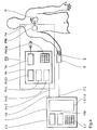
- FIG. 4 is a schematic illustration of an arrangement for controlling or programming a pacemaker system PS from a programming device Pr and a pacemaker PM implanted in a patient Pa.
- the programming device has an operating unit Pr / Op and a display unit Pr / Di, and within the device two setting functions are symbolized by blocks Pr / 1 and Pr / 2.
- Pacemaker PM and programming device Pr are connected to one another via a telemetry unit Tel, via which operating parameter settings made on the programming device are transmitted to the pacemaker.
- a pulse oximeter 1 for detecting blood oxygen saturation is provided as a device for measuring a quantity reflecting the metabolic or hemodynamic state of the patient.
- This includes a measuring probe S which receives a finger 2 of the patient Pa.
- the measuring probe S is connected to an input 1 / I of the pulse oximeter 1, and this is connected via an output 1 / O to an input Pr / I of the programming unit Pr of the pacemaker system PS.
- the pulse oximeter 1 is shown in more detail in FIGS. 7 to 11 and is described in detail in the associated part of the description.
- a display unit 1.6 and an operating unit 1.7 are shown individually from the structure thereof;
- the assemblies 1.1 to 1.5 shown in FIG. 7 are symbolized in FIG. 4 as a block (shown in broken lines).
- a measured value and setting memory 1 / M is provided in the pulse oximeter 1.
- the first external i.e. Via the programming unit Pr, the setting function Pr / 1 to be implemented, which is related to the hemodynamic state of the patient Pa, is called, for example the setting of the stimulation rate.
- a measurement series is formed with the setting valid until the examination and other basic settings provided in the system.
- a setting value is transmitted to the pacemaker PM via the telemetry unit Tel and the heart H of the patient Pa is stimulated with this value by the pacemaker over a period of time specified on the programming device Pr.
- the pulse oximeter 1 uses the measuring probe S to measure the blood oxygen saturation, and the blood oxygen saturation value obtained for the set stimulation rate value is assigned to the rate value in Programming device saved, the number of the measurement in the series of measurements or directly the rate or frequency value can serve as an address.
- the next value of the stimulation rate is then called up and the procedure described is repeated for it.
- the transmission current automatically set during the measurement for the LEDs (not shown in FIG. 4) is stored in the measuring probe S under the patient's name, so that in later analog tests on the same patient immediately from the correct settings of the sensor arrangement can be assumed.
- the highest value of blood oxygen saturation is automatically determined (in the manner described in more detail below), stored in the internal memory 1 / M of pulse oximeter 1 under the patient's name and the associated rate value via the programmer Pr transmitted to the pacemaker PM as the new, final setting value for the patient's exercise level examined with the series of measurements.
- the second setting Pr / 2 for example the AV delay of a two-chamber pacemaker PM (which is described in more detail below) at one or more predetermined rate value (s), can be optimized in a further series of measurements or series of series of measurements.
- the control of the pacemaker then takes place in such a way that an activity or stress sensor assigned to it is implanted Signal is issued, from which the above-mentioned identifier for the load state is obtained, and that the associated stored rate and AV delay value is set. (This is also explained in more detail below.)
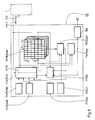
- FIG. 5 is a highly simplified block diagram to illustrate the structure and function of the programming device Pr in a (functionally slightly modified) configuration according to FIG. 4.
- the arrangement differs from the one described above in that it also optimizes the rate and AV delay time a changed process allowed.
- the heart of the programming device Pr is a microprocessor unit Pr / CPU, which in a manner known per se is associated with a program memory Pr / ROM and a data memory Pr / RAM and, as already shown in FIG. 4, a display unit Pr / Di and a control panel Pr / Op are.
- An auxiliary memory Pr / MAux which is organized in several levels in a matrix-like manner, is of particular importance for carrying out the check / readjustment of the pacemaker operating parameters (AV delay and stimulation rate selected here as an example).
- Its column addresses are the individual stimulation frequency values f 1 ... f n available in the data memory Pr / RAM under specification for the implanted pacemaker and its row addresses are the respectively available AV delay values AV 1 ... AV n .
- the memory levels here stand for the individual measurements of a combined rate / AV delay measurement series.
- the blood oxygen saturation value SaO2 measured for a specific combination of frequency and AV delay value is stored in a respectively addressed memory field stored. (For an overall presentation and details of the organization and handling of such memories for operating parameter maps, reference is made to EP-B-0 222 681 here.)
- the programming device Pr has a comparator unit Pr / Com connected on the input side to the data output of the auxiliary memory Pr / MAux and on the output side with an operating parameter register Pr / Reg for evaluating the measured values of the blood oxygen saturation. It also includes a criteria read-only memory (ROM) Pr / MCri connected to a control input of the comparator unit Pr / Com for storing one or more comparison criteria or values as the basis for evaluating the blood oxygen saturation, and one - in the figure as part of the Pr / CPU shown - timing control Pr / Ti for the execution of the measurements and the subsequent comparison procedure.
- ROM read-only memory
- the procedure described above with reference to FIG. 4 is practiced for readjusting or calibrating the pacemaker;
- the stimulation rate and AV delay are not optimized successively in two separate series of measurements, but rather (quasi "two-dimensionally") in one series of measurements.
- An operating mode and an operating parameter correlation - in this case the correlation f / AV - are preselected via the control panel Pr / Op of the programming device and read from the program memory Pr / ROM.
- the sets f 1 ... f n and AV 1 ... AV m automatically become available operating parameters from the data memory Pr / RAM read out and the current organization of the auxiliary memory Pr / MAux specified.
- the preselected pair of parameters is transferred to the Pr / Reg operating parameter register and transmitted to the pacemaker PM via the telemetry system Tel.
- the pulse generator is set for a specific period of time specified by the time control unit Pr / Ti of the programming device (the course of which is signaled by the telemetry unit simply by transmitting a new pair of parameters).
- the blood oxygen saturation is measured in the manner described below and the measured value at the address ( f i , AV i ) in the auxiliary memory Pr / MAux and simultaneously (together with the current parameters) shown on the display device Pr / Di for the doctor.
- the results of the comparison can be shown on the display unit Pr / Di.
- the associated address is loaded into the operating parameter register Pr / Reg, so that at the end of the comparison procedure, the address in this register that belongs to the highest SaO 2 value and the represents the optimal operating parameter combination f / AV for the underlying load condition. This is shown on the display unit Pr / Di and transmitted to the pacemaker via the telemetry unit, where it is stored (as explained in more detail below).
- the pacemaker for the selected operating mode contains a hemodynamically optimized set of parameter pairs (f k , AV k ) , based on which the load-dependent control of the pacemaker can take place in the future.
- FIG. 6 shows a simplified block diagram of an AV sequential two-chamber pacemaker 201, which can be set or calibrated with an arrangement according to an embodiment of the invention
- the core element is a control unit 202, to which a circuit 203 for "run-away" protection and a program decoder 204 are directly assigned.
- a battery 205 with a downstream EOL indicator 206 supplies the modules with energy.
- a program and operating data register 212 is loaded via a receiver coil 208, a receiver 209, a program amplifier 210 and a safety circuit 211 for program checking, from which program data can be queried by the control unit 202.
- the program register is loaded via a programming device with a telemetry unit, as is sketched in FIG. 5.
- a pacemaker K is assigned to the pacemaker 201, which comprises a (right) atrial and a (right) ventricular electrode arrangement EA or EV with conventional sensing and stimulation functions. Furthermore, an activity sensor Act, which is also known as such, is assigned to it, which emits signals representing the physical activity of the patient and thus his or her load.
- Heart action potentials are detected via the electrode arrangements EA and EV and via an input amplifier 213 for atrial signals and an input amplifier 214 for ventricular signals (each with downstream fault detection circuit 215 or 216) supplied to the control unit 202.
- the measurement signals of the activity sensor Act are fed to an evaluation unit 217.
- the output signal of this unit 217 is also fed to the control unit 202 for pacemaker operation, where it is used for the ongoing setting of the stimulation rate and / or the AV delay in accordance with the metabolic need of the patient corresponding to the proven activity level, while the demand is measured via the cardiac action potentials measured intracardially Operation of the pacemaker 201 is controlled.
- the valid correlation between the parameter pair stimulation rate / AV delay and the load or activity of the patient is set during the periodic follow-up examinations.
- the program and operating parameter memory 212 comprises a memory area which can be freely addressed by output signals from the evaluation unit 217 (i.e. by processed activity signals) and in which the valid f / AV pairs for different load conditions are stored during the examination.
- a memory area is then addressed by the activity signal prepared and the pair of parameters stored therein is called up to control the pulse generator.
- the stimulation pulses generated with corresponding parameters are delivered to the electrode arrangements EA and EV via an output amplifier circuit 218 and 219, respectively, and are transmitted from there to the excitable heart tissue.
- Blood oxygen saturation can of course also be used to optimize only one pacemaker operating parameter - for example the AV delay alone at a given stimulation rate - and the pacemaker can be programmed by further measurements using other methods (e.g. physical activity directly, impedance measurements, etc.) be additionally supported.
- other methods e.g. physical activity directly, impedance measurements, etc.
- FIG. 7 is a simplified block diagram of a device 1 for the extracorporeal determination of blood oxygen saturation, in the figure on a finger 2.
- the device comprises a transmission stage 1.1 with a transmitter-side red channel 1.1a and a transmitter-side infrared channel 1.1b and a reception stage 1.2 with a receiver-side red channel 1.2a and a receiver-side infrared channel 1.2b.
- the receiver and the transmitter-side red or infrared channels 1.1a and 1.2a or 1.1b and 1.2b form two separate measuring channels 1a and 1b for determining the transmission with visible light with a wavelength of 660 or with infrared radiation with one 950 nm wavelength.
- the transmitter stage includes one emitting at 660 nm, i.e. red-lit LED 3a with a direct voltage supply 4a and an alternating voltage supply 5a for tone-frequency (1 kHz) modulation of the emitted light in the first channel 1a.
- red-lit LED 3a with a direct voltage supply 4a and an alternating voltage supply 5a for tone-frequency (1 kHz) modulation of the emitted light in the first channel 1a.
- it comprises an LED 3b emitting infrared at 950 nm with a direct voltage supply 4b and an alternating voltage supply 5b for 1 kHz modulation of the emitted IR radiation in the second channel 1b.
- the radiation of both LEDs is in a distance range A of a (not shown in the figure) housing, in which the Finger 2 is inserted, emitted and picked up by a photodetector (a PIN diode) 6a or 6b opposite the LED 3a or 3b.
- An optical bandpass filter 7a is connected upstream of the photodetector 6a in the red channel 1a.
- the signals supplied by the respective photodetectors 6a and 6b subsequently run through analog processing paths. They are first amplified in an amplifier 8a or 8b, after which the signal path branches.
- a first signal path leads through a 40 Hz low-pass filter 9a or 9b and a 0.1Hz high-pass filter 10a or 10b and delivers a plethysmogram or.
- a quotient formation in a subordinate arithmetic processing stage 1.3 provides approximately a value from this, from which SaO2 can be read using the curve shown in FIG. 3.
- a second signal path leads through a 1 kHz bandpass filter 11a or 11b, at the output of which a first correction signal S C1 (R) or S C1 (IR) is continuously available to determine the transmission efficiency of the sample (finger 2). This is done by comparing the received amplitude of the 1 kHz pilot signal with the original, modulated pilot signal in a first pilot signal processing and comparator unit 1.4a or 1.4b.
- a third signal path leads through a 3 kHz bandpass filter 12a or 12b, at the output of which a second correction signal S C2 (R) or S C2 (IR) is available, which is used to detect harmonic distortions due to non-linear operation of the components can. This happens again by comparative processing with the original 1 kHz signal in a second pilot signal processing and comparator unit 1.5a and 1.5b, respectively.
- the evaluation of the transmission efficiency also makes it possible to have standardized data available for measurements on a patient at different times and for measurements on a patient population.
- the transmission data obtained in both channels can be stored in a patient file for a patient and previous values can be passed with the values of current measurements.
- S C2 (R ) or S C2 (IR) a control device (not shown in the figure) is actuated, which controls the direct current supply 4a or 4b in such a way that the LED current for the LEDs 3a or 3b is calibrated in predetermined steps until none Distortion no longer occurs, ie no signal S C2 (R) or S C2 (IR) can be detected.
- This setting can also be saved for a special patient in his patient file so that this setting can be started in a later examination.
- the measuring probe is not connected or the probe cable is defective, and the operator is shown appropriate information on the display 1.6.
- FIG. 8 shows a connection diagram and component specifications for the actual measuring probe according to FIG. 7 (slightly modified by using three LEDs in the red and infrared channels).
- the reference numerals are - except for the corresponding replacement of the numbers 3a by 3a 'or 3b by 3b' - the same as in Fig. 7, and the circuit as such will not be described again.
- the first four signals can be transmitted on a double line with simple shielding, the shielding of which is connected to a central 0V reference point.
- Minimal crosstalk is achieved through a 180 ° phase shift between the red and infrared pilot tones.
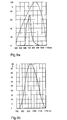
- FIGS. 9a and 9b are representations of the sensitivity curves of the red and IR reception component 6a (with an upstream optical filter 7a) and 6b (with an integrated optical filter) of the device shown in FIG. 7.
- a PIN diode Siemens BPW34 is used as detector 6a in the red channel la, the spectral sensitivity curve of which has the shape of the dashed curve in FIG. 9a. It can be seen that the detector is sensitive in the wavelength range from approximately 400 to approximately 1100 nm, while detection is only required around 660 nm and that the sensitivity in the short as well as in the longer wavelength range deteriorates the measuring accuracy of the device.
- the detector is therefore equipped with an Edmund Scientific G39.424 IR cut filter and a filter to suppress shorter wavelengths, such as the Siemens BPW21 photodetector. Overall, the solid transmission curve then results with the composite filter 7a.
- 9b shows the spectral sensitivity curve of the Siemens BPW34F PIN diode used as an IR detector with an integrated daylight filter. It can be seen that there is practically no transmission below 750 nm, so that excellent channel separation red-infrared and almost complete insensitivity to interference from visible light is achieved.
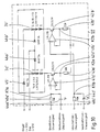
- FIG. 10 is a detailed illustration of the LED control in a pulse oximeter 1 ′ modified with respect to the device according to FIG. 7, of which only the transmission stage 1.1 ′ is shown in FIG. 10.
- the reception stage can be designed according to FIG. 7 or FIG. 11 explained below.
- the transmission stage comprises a red transmitter group 3a 'and an infrared transmitter group 3b' each consisting of three LEDs.
- the specification of the transmit components (as for the other components) is given in the figure.
- the red and infrared channels have separate voltage-controlled current sources.
- a direct current control signal (10 mA / V for red, 15 mA / V for infrared) is fed via a resistor 40a 'or 40b' and a node K1a or K1b to the non-inverting input of an operational amplifier 41a 'or 41b', whose inverting input is connected via a node K2a or K2b on the one hand to the emitter of an npn transistor 42a 'or 42b' and on the other hand via a resistor 43a 'or 43b' to ground.
- An alternating current control signal (for the 1 kHz pilot signal) is also supplied to the non-inverting via the capacitor 44a 'or 44b' via the node K1a or K1b Input of the operational amplifier 41a 'or 41b' supplied.
- the outputs of the operational amplifiers 41a 'and 41b' are each connected to the base of the transistors 42a 'and 42b'.
- the collectors of the transistors 42a 'and 42b' are either via the (complete) transmitter element group 3a 'or 3b' and a diode 45 'with a + 12V supply voltage ("Bright") or - if only two LEDs are used - connected to the + 12V supply voltage ("Dim”) via two LEDs of the transmitter element group and one diode 46a 'or 46b' each.
- the operational amplifiers 41a ', 41b' control the collector current and thus the operating current of the LED groups 3a 'and 3b' as a function of the applied direct and alternating current control signals in a manner known per se via the transistors 42a ', 42b' in a basic circuit.
- FIG. 11 is a partial representation of the reception stage, especially the evaluation circuit, of a pulse oximeter somewhat modified compared to the device according to FIG. 7, both channels being constructed in the same way and only the red channel 1 a 'being shown here. 7 is the guidance of the measurement signal coming from the PIN diode 6a over three separate signal paths, which are designated in FIG. 11 with 1.21 ', 1.22' and 1.23 'and on which output signals S O (R) , S c1 (R) or S C2 (R) can be supplied.
- In signal path 1.21 ' is one of a resistor 80a', a further resistor 81a ', a capacitor 82a' connected in parallel with this, a capacitor 83a 'separating resistor 81a' from ground, an operational amplifier 84a 'and two further resistors 85a' and 86a ' Low-pass filter and amplifier circuit are provided, the non-inverting input of operational amplifier 84a 'being connected in series with one another through resistors 80a' and 81a 'to the output of the photodetector and via capacitor 83a' to ground, its inverting input being connected via resistor 85a ' to ground and its output through resistor 86a 'to ground, through capacitor 82a' to the junction between series resistors 80a 'and 81a' and to the next processing stage.
- FIG. 11 shows the connection of the operational amplifier (and also of the further operational amplifiers described further below) to the power supply and - via two capacitors not provided with reference numbers - to ground.
- the signal passes into a capacitor 100a', a further capacitor 101a ', a series circuit made up of two resistors 102a', 103a 'parallel to the latter, and a series circuit made up of two resistors separating the capacitor 101a' from ground 104a ', 105a', an operational amplifier 106a 'and two further resistors 107a' and 108a 'formed high-pass filter and amplifier circuit, in which the non-inverting input of the operational amplifier 106a' via the capacitors connected in series with the input of this stage and over resistors 104a ', 105a' to ground, its inverting input through resistor 107a 'to ground and its output through resistor 108a' to ground and through series resistors 102a ', 103a' to the connection point between the capacitors 100a ', 101a' is connected and simultaneously forms the output of the first signal path 1.21 '.
- the operational amplifier circuit shown realizes - in addition to the 40 Hz low pass and the 0.1 Hz high pass as a filter with approximate Bessel characteristics and low phase distortions - a NIC converter ("Transimpedance Amplifier") with which the non-linearity of the optical components in a certain Way is compensated.
- a NIC converter Transimpedance Amplifier
- the second and third signal paths 1.22 'and 1.23' are constructed in the same way and differ only in the dimensioning of the components (indicated in the figure), so that in the figure only the second signal path is provided with reference numbers and only this is described here.
- It contains a resistor 110a ', a parallel connection of two capacitors 111a', 112a 'and an operational amplifier 113a', the inverting input of which via the aforementioned elements is connected on the one hand to the input of the stage and on the other hand with an RC parallel circuit 114a ' is connected and its non-inverting input is connected to ground via the tap of a potentiometer 115a '.
- the output of the operational amplifier 113a ' is connected to ground on the one hand via a resistor 116a' and the potentiometer 115a 'and is connected on the one hand to the parallel RC circuit 114a' and on the other hand to the input of a forward-connected diode 117a '. Its output - separated from ground by an RC parallel circuit consisting of an electrolytic capacitor 118a 'and a resistor 119a' - forms the output of the signal path 1.22 '.
- Deviations from the circuits shown are possible for the person skilled in the art at any time, whereby the principle of the detection of harmonic distortions can also be modified via a pilot signal.
- the embodiment of the invention is not limited to the preferred exemplary embodiment specified above. Rather, a number of variants are conceivable which make use of the solution shown, even in the case of fundamentally different types.
Landscapes
- Health & Medical Sciences (AREA)
- Cardiology (AREA)
- Heart & Thoracic Surgery (AREA)
- Life Sciences & Earth Sciences (AREA)
- Engineering & Computer Science (AREA)
- Biomedical Technology (AREA)
- General Chemical & Material Sciences (AREA)
- Biophysics (AREA)
- Chemical Kinetics & Catalysis (AREA)
- Physiology (AREA)
- Chemical & Material Sciences (AREA)
- Hematology (AREA)
- Nuclear Medicine, Radiotherapy & Molecular Imaging (AREA)
- Radiology & Medical Imaging (AREA)
- Animal Behavior & Ethology (AREA)
- General Health & Medical Sciences (AREA)
- Public Health (AREA)
- Veterinary Medicine (AREA)
- Measurement Of The Respiration, Hearing Ability, Form, And Blood Characteristics Of Living Organisms (AREA)
- Electrotherapy Devices (AREA)
Applications Claiming Priority (2)
| Application Number | Priority Date | Filing Date | Title |
|---|---|---|---|
| DE19609368A DE19609368A1 (de) | 1996-03-04 | 1996-03-04 | Vorrichtung zur Steuerung eines Herzstimulators aufgrund der Blutsauerstoffsättigung |
| DE19609368 | 1996-03-04 |
Publications (3)
| Publication Number | Publication Date |
|---|---|
| EP0793975A2 true EP0793975A2 (fr) | 1997-09-10 |
| EP0793975A3 EP0793975A3 (fr) | 1998-12-16 |
| EP0793975B1 EP0793975B1 (fr) | 2004-05-06 |
Family
ID=7787852
Family Applications (1)
| Application Number | Title | Priority Date | Filing Date |
|---|---|---|---|
| EP97250053A Expired - Lifetime EP0793975B1 (fr) | 1996-03-04 | 1997-03-04 | Dispositif de commande d'un stimulateur cardiaque basé sur la saturation d'oxygène dans le sang |
Country Status (2)
| Country | Link |
|---|---|
| EP (1) | EP0793975B1 (fr) |
| DE (2) | DE19609368A1 (fr) |
Cited By (5)
| Publication number | Priority date | Publication date | Assignee | Title |
|---|---|---|---|---|
| WO2003043694A3 (fr) * | 2001-11-16 | 2003-11-20 | Cardiac Pacemakers Inc | Optimisation des parametres de stimulation cardiaque et surveillance des dysfonctions du coeur |
| US7231248B2 (en) | 2001-03-16 | 2007-06-12 | Cardiac Pacemakers, Inc. | Resynchronization method and apparatus based on intrinsic atrial rate |
| US8046069B2 (en) | 2005-12-22 | 2011-10-25 | Cardiac Pacemakers, Inc. | Method and apparatus for control of cardiac therapy using non-invasive hemodynamic sensor |
| EP3103391A3 (fr) * | 2015-05-21 | 2017-04-19 | BIOTRONIK SE & Co. KG | Dispositif implantable comprenant un capteur d'oxygene et procede de fonctionnement d'un dispositif implantable comprenant un capteur d'oxygene |
| US9709638B2 (en) | 2014-09-01 | 2017-07-18 | Biotronik Se & Co. Kg | Implant with MRI device recognition |
Families Citing this family (1)
| Publication number | Priority date | Publication date | Assignee | Title |
|---|---|---|---|---|
| DE19720755B4 (de) * | 1997-05-07 | 2004-07-29 | Biotronik Meß- und Therapiegeräte GmbH & Co. Ingenieurbüro Berlin | Vorrichtung zur Ermittlung der optimalen AV-Verzögerungszeit |
Citations (5)
| Publication number | Priority date | Publication date | Assignee | Title |
|---|---|---|---|---|
| EP0222681A1 (fr) * | 1985-09-17 | 1987-05-20 | BIOTRONIK Mess- und Therapiegeräte GmbH & Co Ingenieurbüro Berlin | Stimulateur cardiaque |
| EP0319158A1 (fr) * | 1987-12-02 | 1989-06-07 | The Boc Group, Inc. | Procédé et appareil de surveillance des constituants sanguins avec séparation de fréquence par multiplexage |
| EP0443495A2 (fr) * | 1990-02-21 | 1991-08-28 | Pacesetter, Inc. | Stimulateur cardiaque à rythme commandé par une grandeur hémodynamique |
| US5487752A (en) * | 1994-11-15 | 1996-01-30 | Cardiac Pacemakers, Inc. | Automated programmable stimulating device to optimize pacing parameters and method |
| US5540727A (en) * | 1994-11-15 | 1996-07-30 | Cardiac Pacemakers, Inc. | Method and apparatus to automatically optimize the pacing mode and pacing cycle parameters of a dual chamber pacemaker |
Family Cites Families (21)
| Publication number | Priority date | Publication date | Assignee | Title |
|---|---|---|---|---|
| US4444498A (en) * | 1981-02-27 | 1984-04-24 | Bentley Laboratories | Apparatus and method for measuring blood oxygen saturation |
| US4447150A (en) * | 1981-02-27 | 1984-05-08 | Bentley Laboratories | Apparatus and method for measuring blood oxygen saturation |
| DE3506791A1 (de) * | 1985-02-22 | 1986-08-28 | Biotronik Meß- und Therapiegeräte GmbH & Co Ingenieurbüro Berlin, 1000 Berlin | Herzschrittmacher mit physiologischer steuerung |
| ZA861179B (en) * | 1985-02-28 | 1986-12-30 | Boc Group Inc | Oximeter |
| DE3687388D1 (de) * | 1985-09-17 | 1993-02-11 | Biotronik Mess & Therapieg | Herzschrittmacher. |
| US4813421A (en) * | 1986-08-15 | 1989-03-21 | Medtronic, Inc. | Oxygen sensing pacemaker |
| US4903701A (en) * | 1987-06-05 | 1990-02-27 | Medtronic, Inc. | Oxygen sensing pacemaker |
| DE3723881A1 (de) * | 1987-07-18 | 1989-01-26 | Nicolay Gmbh | Verfahren zum ermitteln der sauerstoffsaettigung des blutes eines lebenden organismus und elektronische schaltung sowie vorrichtung zum durchfuehren dieses verfahrens |
| US4805623A (en) * | 1987-09-04 | 1989-02-21 | Vander Corporation | Spectrophotometric method for quantitatively determining the concentration of a dilute component in a light- or other radiation-scattering environment |
| US4882492A (en) * | 1988-01-19 | 1989-11-21 | Biotronics Associates, Inc. | Non-invasive near infrared measurement of blood analyte concentrations |
| US5122974A (en) * | 1989-02-06 | 1992-06-16 | Nim, Inc. | Phase modulated spectrophotometry |
| US4972331A (en) * | 1989-02-06 | 1990-11-20 | Nim, Inc. | Phase modulated spectrophotometry |
| US5119815A (en) * | 1988-12-21 | 1992-06-09 | Nim, Incorporated | Apparatus for determining the concentration of a tissue pigment of known absorbance, in vivo, using the decay characteristics of scintered electromagnetic radiation |
| US5187672A (en) * | 1989-02-06 | 1993-02-16 | Nim Incorporated | Phase modulation spectroscopic system |
| US5028787A (en) * | 1989-01-19 | 1991-07-02 | Futrex, Inc. | Non-invasive measurement of blood glucose |
| DK0613652T3 (da) * | 1990-02-15 | 1997-08-25 | Hewlett Packard Gmbh | Apparat og fremgangsmåde til ikke invasiv måling af oxygenmåling |
| DE4213993A1 (de) * | 1991-05-14 | 1992-12-03 | Straube Juergen Dr Med | Integriertes patientenwarnsystem fuer energiebetriebene implantate |
| DK0541338T3 (da) * | 1991-11-04 | 1996-12-02 | Cardiac Pacemakers Inc | Implanterbar indretning til overvågning og stimulering af hjertet til diagnose og terapi |
| DE4233423A1 (de) * | 1992-04-07 | 1993-10-14 | Ieg Ind Engineering Gmbh | Kläreinrichtung für Abwässer |
| US5342406A (en) * | 1992-10-07 | 1994-08-30 | Medtronic, Inc. | Oxygen sensor based capture detection for a pacer |
| US5312454A (en) * | 1992-12-14 | 1994-05-17 | Medtronic, Inc. | Apparatus and method of automatically adjusting a sensor signal comparator threshold for an oxygen sensing pacemaker |
-
1996
- 1996-03-04 DE DE19609368A patent/DE19609368A1/de not_active Ceased
-
1997
- 1997-03-04 EP EP97250053A patent/EP0793975B1/fr not_active Expired - Lifetime
- 1997-03-04 DE DE59711586T patent/DE59711586D1/de not_active Expired - Lifetime
Patent Citations (5)
| Publication number | Priority date | Publication date | Assignee | Title |
|---|---|---|---|---|
| EP0222681A1 (fr) * | 1985-09-17 | 1987-05-20 | BIOTRONIK Mess- und Therapiegeräte GmbH & Co Ingenieurbüro Berlin | Stimulateur cardiaque |
| EP0319158A1 (fr) * | 1987-12-02 | 1989-06-07 | The Boc Group, Inc. | Procédé et appareil de surveillance des constituants sanguins avec séparation de fréquence par multiplexage |
| EP0443495A2 (fr) * | 1990-02-21 | 1991-08-28 | Pacesetter, Inc. | Stimulateur cardiaque à rythme commandé par une grandeur hémodynamique |
| US5487752A (en) * | 1994-11-15 | 1996-01-30 | Cardiac Pacemakers, Inc. | Automated programmable stimulating device to optimize pacing parameters and method |
| US5540727A (en) * | 1994-11-15 | 1996-07-30 | Cardiac Pacemakers, Inc. | Method and apparatus to automatically optimize the pacing mode and pacing cycle parameters of a dual chamber pacemaker |
Cited By (9)
| Publication number | Priority date | Publication date | Assignee | Title |
|---|---|---|---|---|
| US7231248B2 (en) | 2001-03-16 | 2007-06-12 | Cardiac Pacemakers, Inc. | Resynchronization method and apparatus based on intrinsic atrial rate |
| WO2003043694A3 (fr) * | 2001-11-16 | 2003-11-20 | Cardiac Pacemakers Inc | Optimisation des parametres de stimulation cardiaque et surveillance des dysfonctions du coeur |
| US6832113B2 (en) | 2001-11-16 | 2004-12-14 | Cardiac Pacemakers, Inc. | Non-invasive method and apparatus for cardiac pacemaker pacing parameter optimization and monitoring of cardiac dysfunction |
| US7366569B2 (en) | 2001-11-16 | 2008-04-29 | Cardiac Pacemakers, Inc. | Non-invasive method and apparatus for cardiac pacemaker pacing parameter optimization and monitoring of cardiac dysfunction |
| US8046069B2 (en) | 2005-12-22 | 2011-10-25 | Cardiac Pacemakers, Inc. | Method and apparatus for control of cardiac therapy using non-invasive hemodynamic sensor |
| US8798747B2 (en) | 2005-12-22 | 2014-08-05 | Cardiac Pacemakers, Inc. | Method and apparatus for control of cardiac therapy using non-invasive hemodynamic sensor |
| US9709638B2 (en) | 2014-09-01 | 2017-07-18 | Biotronik Se & Co. Kg | Implant with MRI device recognition |
| EP3103391A3 (fr) * | 2015-05-21 | 2017-04-19 | BIOTRONIK SE & Co. KG | Dispositif implantable comprenant un capteur d'oxygene et procede de fonctionnement d'un dispositif implantable comprenant un capteur d'oxygene |
| US10213161B2 (en) | 2015-05-21 | 2019-02-26 | Biotronik Se & Co. Kg | Implantable device with an oxygen sensor and a method of operating an implantable device with an oxygen sensor |
Also Published As
| Publication number | Publication date |
|---|---|
| DE19609368A1 (de) | 1997-09-11 |
| DE59711586D1 (de) | 2004-06-09 |
| EP0793975B1 (fr) | 2004-05-06 |
| EP0793975A3 (fr) | 1998-12-16 |
Similar Documents
| Publication | Publication Date | Title |
|---|---|---|
| DE19612425C2 (de) | Apparat zur Messung von Hämoglobinkonzentration | |
| DE69727776T2 (de) | Verfahren zum bestimmen der fraktionellen sauerstoffsaturation | |
| DE19537646C2 (de) | Verfahren und Vorrichtung zum Erkennen verfälschter Meßwerte in der Pulsoximetrie zur Messung der Sauerstoffsättigung | |
| EP0215729B1 (fr) | Stimulateur cardiaque | |
| DE69836558T2 (de) | Verfahren und vorrichtung zur bestimmung einer konzentration | |
| EP0215730B1 (fr) | Stimulateur cardiaque | |
| DE69924749T2 (de) | Generisch integrierte implantierbare Potentiostatfernmeßanordnung für elektrochemische Fühler | |
| DE602004009894T2 (de) | Implantierbarer chemischer Sensor | |
| EP0793942B1 (fr) | Dispositif pour déterminer la saturation d'oxygène du sang | |
| DE3528369A1 (de) | Spektralphotometer und spektralphotometrisches verfahren | |
| WO2008116835A1 (fr) | Procédé de détermination continue non-invasive de la concentration de composants sanguins | |
| DE102007003341A1 (de) | Okularsensor zum Nachweis eines Analyten in einer Augenflüssigkeit | |
| WO2003079899A1 (fr) | Dispositif et procede de mesure de constituants du sang | |
| DE112009002132T5 (de) | Drahtloses medizinisches Überwachungssystem | |
| EP0216725B1 (fr) | Stimulateur cardiaque | |
| EP0783902A2 (fr) | Dispositif de contrÔle extracorporel pour un dispositif médical implantable | |
| DE102013019660A1 (de) | Vorrichtung zur optischen Messung biometrischer Parameter eines Tieres, einer Pflanze oder eines Menschen | |
| DE4427845A1 (de) | Verfahren zur Aufnahme von für Herzaktionen charakteristischen Signalen und Vorrichtung zu dessen Durchführung | |
| EP0793975B1 (fr) | Dispositif de commande d'un stimulateur cardiaque basé sur la saturation d'oxygène dans le sang | |
| EP1335666B1 (fr) | Capteur et procede pour la mesure de parametres physiologiques | |
| DE3825352C2 (fr) | ||
| WO2017202847A1 (fr) | Dispositif de détection | |
| EP0222681B1 (fr) | Stimulateur cardiaque | |
| DE3134124A1 (de) | Verfahren und geraet zur ueberwachung der sauerstoffsaettigung des blutes in vivo | |
| WO1995013739A1 (fr) | Procede et dispositif de determination percutanee non invasive de la concentration de substances presentes dans des liquides ou des tissus du corps humain |
Legal Events
| Date | Code | Title | Description |
|---|---|---|---|
| PUAI | Public reference made under article 153(3) epc to a published international application that has entered the european phase |
Free format text: ORIGINAL CODE: 0009012 |
|
| AK | Designated contracting states |
Kind code of ref document: A2 Designated state(s): DE FR GB IT NL SE |
|
| PUAL | Search report despatched |
Free format text: ORIGINAL CODE: 0009013 |
|
| AK | Designated contracting states |
Kind code of ref document: A3 Designated state(s): DE FR GB IT NL SE |
|
| 17P | Request for examination filed |
Effective date: 19990218 |
|
| 17Q | First examination report despatched |
Effective date: 20030327 |
|
| GRAP | Despatch of communication of intention to grant a patent |
Free format text: ORIGINAL CODE: EPIDOSNIGR1 |
|
| GRAS | Grant fee paid |
Free format text: ORIGINAL CODE: EPIDOSNIGR3 |
|
| GRAA | (expected) grant |
Free format text: ORIGINAL CODE: 0009210 |
|
| AK | Designated contracting states |
Kind code of ref document: B1 Designated state(s): DE FR GB IT NL SE |
|
| REG | Reference to a national code |
Ref country code: GB Ref legal event code: FG4D Free format text: NOT ENGLISH |
|
| REF | Corresponds to: |
Ref document number: 59711586 Country of ref document: DE Date of ref document: 20040609 Kind code of ref document: P |
|
| REG | Reference to a national code |
Ref country code: SE Ref legal event code: TRGR |
|
| GBT | Gb: translation of ep patent filed (gb section 77(6)(a)/1977) |
Effective date: 20040628 |
|
| ET | Fr: translation filed | ||
| PLBE | No opposition filed within time limit |
Free format text: ORIGINAL CODE: 0009261 |
|
| STAA | Information on the status of an ep patent application or granted ep patent |
Free format text: STATUS: NO OPPOSITION FILED WITHIN TIME LIMIT |
|
| 26N | No opposition filed |
Effective date: 20050208 |
|
| PGFP | Annual fee paid to national office [announced via postgrant information from national office to epo] |
Ref country code: NL Payment date: 20070319 Year of fee payment: 11 |
|
| PGFP | Annual fee paid to national office [announced via postgrant information from national office to epo] |
Ref country code: GB Payment date: 20070323 Year of fee payment: 11 |
|
| PGFP | Annual fee paid to national office [announced via postgrant information from national office to epo] |
Ref country code: SE Payment date: 20070326 Year of fee payment: 11 |
|
| PGFP | Annual fee paid to national office [announced via postgrant information from national office to epo] |
Ref country code: IT Payment date: 20070605 Year of fee payment: 11 |
|
| PGFP | Annual fee paid to national office [announced via postgrant information from national office to epo] |
Ref country code: FR Payment date: 20070321 Year of fee payment: 11 |
|
| EUG | Se: european patent has lapsed | ||
| GBPC | Gb: european patent ceased through non-payment of renewal fee |
Effective date: 20080304 |
|
| PG25 | Lapsed in a contracting state [announced via postgrant information from national office to epo] |
Ref country code: NL Free format text: LAPSE BECAUSE OF NON-PAYMENT OF DUE FEES Effective date: 20081001 |
|
| NLV4 | Nl: lapsed or anulled due to non-payment of the annual fee |
Effective date: 20081001 |
|
| REG | Reference to a national code |
Ref country code: FR Ref legal event code: ST Effective date: 20081125 |
|
| PG25 | Lapsed in a contracting state [announced via postgrant information from national office to epo] |
Ref country code: SE Free format text: LAPSE BECAUSE OF NON-PAYMENT OF DUE FEES Effective date: 20080305 |
|
| PG25 | Lapsed in a contracting state [announced via postgrant information from national office to epo] |
Ref country code: FR Free format text: LAPSE BECAUSE OF NON-PAYMENT OF DUE FEES Effective date: 20080331 |
|
| PG25 | Lapsed in a contracting state [announced via postgrant information from national office to epo] |
Ref country code: GB Free format text: LAPSE BECAUSE OF NON-PAYMENT OF DUE FEES Effective date: 20080304 |
|
| PG25 | Lapsed in a contracting state [announced via postgrant information from national office to epo] |
Ref country code: IT Free format text: LAPSE BECAUSE OF NON-PAYMENT OF DUE FEES Effective date: 20080304 |
|
| REG | Reference to a national code |
Ref country code: DE Ref legal event code: R082 Ref document number: 59711586 Country of ref document: DE |
|
| REG | Reference to a national code |
Ref country code: DE Ref legal event code: R081 Ref document number: 59711586 Country of ref document: DE Owner name: BIOTRONIK SE & CO. KG, DE Free format text: FORMER OWNER: BIOTRONIK MESS- UND THERAPIEGERAETE GMBH & CO. INGENIEURBUERO BERLIN, 12359 BERLIN, DE Effective date: 20111219 |
|
| PGFP | Annual fee paid to national office [announced via postgrant information from national office to epo] |
Ref country code: DE Payment date: 20130408 Year of fee payment: 17 |
|
| REG | Reference to a national code |
Ref country code: DE Ref legal event code: R119 Ref document number: 59711586 Country of ref document: DE |
|
| REG | Reference to a national code |
Ref country code: DE Ref legal event code: R119 Ref document number: 59711586 Country of ref document: DE Effective date: 20141001 |
|
| PG25 | Lapsed in a contracting state [announced via postgrant information from national office to epo] |
Ref country code: DE Free format text: LAPSE BECAUSE OF NON-PAYMENT OF DUE FEES Effective date: 20141001 |