EP0793820B1 - Procede de planification destine a la technique de gestion d'installations industrielles multicomposants - Google Patents
Procede de planification destine a la technique de gestion d'installations industrielles multicomposants Download PDFInfo
- Publication number
- EP0793820B1 EP0793820B1 EP95935855A EP95935855A EP0793820B1 EP 0793820 B1 EP0793820 B1 EP 0793820B1 EP 95935855 A EP95935855 A EP 95935855A EP 95935855 A EP95935855 A EP 95935855A EP 0793820 B1 EP0793820 B1 EP 0793820B1
- Authority
- EP
- European Patent Office
- Prior art keywords
- components
- control
- measuring
- msp
- component
- Prior art date
- Legal status (The legal status is an assumption and is not a legal conclusion. Google has not performed a legal analysis and makes no representation as to the accuracy of the status listed.)
- Expired - Lifetime
Links
- 238000000034 method Methods 0.000 title claims description 61
- 238000009434 installation Methods 0.000 title claims 5
- 239000008186 active pharmaceutical agent Substances 0.000 claims description 12
- 238000004458 analytical method Methods 0.000 claims description 12
- 238000005516 engineering process Methods 0.000 description 26
- 238000005259 measurement Methods 0.000 description 16
- 238000004519 manufacturing process Methods 0.000 description 5
- 238000010276 construction Methods 0.000 description 3
- 238000009529 body temperature measurement Methods 0.000 description 2
- 238000011156 evaluation Methods 0.000 description 1
- 238000012423 maintenance Methods 0.000 description 1
- 238000012986 modification Methods 0.000 description 1
- 230000004048 modification Effects 0.000 description 1
- 238000012544 monitoring process Methods 0.000 description 1
- 238000012545 processing Methods 0.000 description 1
- 230000026676 system process Effects 0.000 description 1
Images
Classifications
-
- G—PHYSICS
- G05—CONTROLLING; REGULATING
- G05B—CONTROL OR REGULATING SYSTEMS IN GENERAL; FUNCTIONAL ELEMENTS OF SUCH SYSTEMS; MONITORING OR TESTING ARRANGEMENTS FOR SUCH SYSTEMS OR ELEMENTS
- G05B19/00—Programme-control systems
- G05B19/02—Programme-control systems electric
- G05B19/418—Total factory control, i.e. centrally controlling a plurality of machines, e.g. direct or distributed numerical control [DNC], flexible manufacturing systems [FMS], integrated manufacturing systems [IMS] or computer integrated manufacturing [CIM]
- G05B19/41865—Total factory control, i.e. centrally controlling a plurality of machines, e.g. direct or distributed numerical control [DNC], flexible manufacturing systems [FMS], integrated manufacturing systems [IMS] or computer integrated manufacturing [CIM] characterised by job scheduling, process planning, material flow
-
- G—PHYSICS
- G05—CONTROLLING; REGULATING
- G05B—CONTROL OR REGULATING SYSTEMS IN GENERAL; FUNCTIONAL ELEMENTS OF SUCH SYSTEMS; MONITORING OR TESTING ARRANGEMENTS FOR SUCH SYSTEMS OR ELEMENTS
- G05B2219/00—Program-control systems
- G05B2219/30—Nc systems
- G05B2219/31—From computer integrated manufacturing till monitoring
- G05B2219/31339—From parameters, build processes, select control elements and their connection
-
- Y—GENERAL TAGGING OF NEW TECHNOLOGICAL DEVELOPMENTS; GENERAL TAGGING OF CROSS-SECTIONAL TECHNOLOGIES SPANNING OVER SEVERAL SECTIONS OF THE IPC; TECHNICAL SUBJECTS COVERED BY FORMER USPC CROSS-REFERENCE ART COLLECTIONS [XRACs] AND DIGESTS
- Y02—TECHNOLOGIES OR APPLICATIONS FOR MITIGATION OR ADAPTATION AGAINST CLIMATE CHANGE
- Y02P—CLIMATE CHANGE MITIGATION TECHNOLOGIES IN THE PRODUCTION OR PROCESSING OF GOODS
- Y02P90/00—Enabling technologies with a potential contribution to greenhouse gas [GHG] emissions mitigation
- Y02P90/02—Total factory control, e.g. smart factories, flexible manufacturing systems [FMS] or integrated manufacturing systems [IMS]
Definitions
- the invention relates to a project planning method for the control technology of a technical consisting of components Investment. It also refers to an institution to carry out the procedure
- DE 42 19 902 A1 describes a system for creating Control data for an automatic production line known, where a process planning system processes accordingly the part drawings submitted plans for manufacturing or manufacture of the parts used manufacturing machines selects and determines their order of use.
- a process planning system processes accordingly the part drawings submitted plans for manufacturing or manufacture of the parts used manufacturing machines selects and determines their order of use.
- Farther is a control method from US 4,807,108 of a production process in which a product is created becomes.
- the invention has for its object a project planning method for the control technology of a component technical system to indicate that at least partially feasible by machine and individually for each technical system is tunable to the system. This is supposed to be with a particularly suitable facility can be achieved.
- the invention is based on the consideration of the overall process for planning the control technology of a technical Plant in several, preferably five, process steps subdivide, each of these process steps such is designed to be inherently independent Module can be carried out mechanically.
- the entire process can be automated; it can but also - depending on the complexity of the technical system - only one or some of the process steps may be automated.
- the process is structured in such a way that it is for the Project planning of the control technology of a technical system from the system as a basis. So the procedure is for any technical system can be used. Starting from The control technology becomes a concept for the technical system individually adapted to the technical system. At a Procedures of this kind are the procedural steps of the creation the measuring and / or control processes, the link the selected components with each other and the assignment of Flow charts for the automation structure are fully automated.
- the selection of components for each measurement and / or control process can be operated manually by operating personnel according to specified criteria respectively. However, in addition to high reliability ensure that the greatest possible variety can be selected on components, the selection is made the components for each measuring and / or control process expediently based on the characteristic of each component, in characteristics stored in a database.
- the characteristic data can, for example, be a complete one include technical description of each component. They include but at least one core data set that is just the basic one Describes how the component works. Especially In an advantageous embodiment, the components are selected exclusively based on these functional core data sets.
- the concepts for the measurement and / or control processes are then passed to the analysis module.
- the analysis module are used for every measurement and / or control process suitable components selected. This selection can be made in advantageously on the basis of the measurement and / or control processes described functional sequences and the basic How the components work.
- For linking these components are used for every measurement and / or control process Schedule formed.
- the flowcharts thus formed are the Linking module forwarded.
- the schedule is assigned in the link module each measuring and / or control process to a predefinable one Automation structure.
- the control technology is in shape an interconnection structure including the required Components and link elements created.
- a memory module connected to the analysis module, in particular in the form of a database for which the components characterize Characteristic data provided.
- the modules are in arranged in a mobile housing. This ensures that the facility for project planning of the control technology of a technical System can be used flexibly and regardless of location.
- FIG. 1 An embodiment of the invention is based on a Drawing explained in more detail.
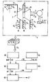
- the figure shows schematically a facility for project planning of the control technology Power plant.
- the - not shown - power plant includes in addition other components, for example a turbine and generator component 1. Within this component 1 is one Turbine 2 via shafts 4, 6 and a gear 8 with a generator 10 connected. To discharge generated in the generator 10 electrical power, a cable system 11 is provided.
- a turbine and generator component 1 Within this component 1 is one Turbine 2 via shafts 4, 6 and a gear 8 with a generator 10 connected.
- a cable system 11 To discharge generated in the generator 10 electrical power, a cable system 11 is provided.
- the turbine 2 which is a steam turbine of a power plant includes a high pressure part 2a and a low pressure part 2 B.
- a high-pressure steam is on the high-pressure part 2a of the turbine 2 supply line 12, a medium pressure steam supply line 14 and a Medium pressure steam discharge line 16 is arranged.
- Steam outlet side is the high pressure part 2a of the turbine 2 via a low pressure steam line 18 with the input of the low pressure part 2b Turbine 2 connected.
- At the outlet of the low pressure part 2b Turbine 2 has a steam discharge 20.
- the high pressure steam supply 12 can be shut off with a valve 22.
- the connecting line 18 can be shut off with a valve 24.
- the turbine and generator component 1 is one of many Components of the power plant.
- the control technology is provided for the power plant.
- To are used - for example for component 1 - for monitoring and control of the operating state relevant parameters recorded and monitored by the control system of the plant. Possibly the operating status of the Power plant affected.
- the parameters required for the operation of each component are mapped to data records.
- the relevant parameters are, for example: the state of the high pressure steam supplied, expressed by pressure p 1 , temperature T 1 and amount of steam Q 1 .
- the state of medium-pressure steam removed from the high-pressure part 2a of the turbine 2 expressed by pressure p 2 , temperature T 2 and amount of steam Q 2 .
- the state of low-pressure steam coupled out of the high-pressure part 2a of the turbine 2 expressed by pressure p 3 , temperature T 3 and amount of steam Q 3 .
- the state of low-pressure steam extracted from the low-pressure part 2b of the turbine 2 expressed by pressure p 4 , temperature T 4 and amount of steam Q 4, and the electrical power generated in generator 10, expressed by current I, voltage U and power P.
- These parameters required for the operation of the turbine and generator component 1 are mapped to data records DS i in a first method step.
- three data records DS 1 , DS 2 and DS 3 are generated for the parameter “state of the high pressure steam supplied”.
- the data set DS 1 describes the pressure p 1
- the data set DS 2 the temperature T 1
- the data set DS 3 the live steam quantity Q 1 of the high pressure steam supplied.
- Each data set includes target values for the parameters and permissible maximum or minimum values.
- the data sets DS i can be generated manually or automatically.
- the data sets DS i are fed to a construction module 40.
- 40 measurement and / or control processes MSP are created in the expansion module on the basis of the data records DS i .
- the information for example data set DS 2 , which reads, for example, "The temperature T 1 of the live steam is to be measured and should be as close as possible to 600 ° C, but not less than 400 ° C and not more than 800 ° C ", used to generate a measuring process MSP 2 .
- the measuring process MSP 2 accordingly comprises a temperature sensor suitable for measuring the temperature T 1 .
- the measuring process MSP 2 can also have, in a manner not shown in detail, an evaluation unit assigned to the temperature sensor for processing data supplied by the temperature sensor and the connecting elements required for data transport.
- an evaluation unit assigned to the temperature sensor for processing data supplied by the temperature sensor and the connecting elements required for data transport.
- the measurement and control processes MSP i are fed to an analysis module 50 via a feed line 45.
- the analysis module 50 is connected to a database 54 via a connecting line 52.
- Characteristic data KD of components are stored in the database 54.
- the characteristic data KD comprise at least the basic functioning of each component.
- the required components are selected in the analysis module 50 for each measuring and control process MSP i .
- This selection is made on the basis of core data sets KS which describe the basic functioning of the component and which are part of the characteristic data KD.
- a suitable temperature sensor is selected for the measuring process MSP 2 , that is to say for the measurement of the temperature T 1 of the fresh steam supplied, in that it is functional in the temperature interval between 300 ° C.
- the other components of the measuring process MSP 2 "temperature measurement of the fresh steam supplied" are selected such that they are compatible with this temperature sensor for measuring the temperature T 1 .
- a flow chart AP i for each measuring and control process MSP i is created in the analysis module 50.
- the selected components are linked in the context of each flow chart AP i .
- the result can be generated, for example, that the temperature sensor is to be connected to a control module via an electrical line.
- This automation structure AS includes information such as "Five automation stations are to be provided, one of the Automation stations is in the area of the power station control room to provide ... ", etc.
- Both the flowcharts AP and the predetermined automation structure AS are fed via a line 56 or 58 to a logic module 60.
- the flow chart AP i of each measurement and control process MSP i is assigned to the automation structure. It is specified, for example, that "the control unit for the temperature measurement of the live steam supplied is to be accommodated in an automation station in the region of the turbine hall". The control technology of the steam power plant is thus created.
- the device for project planning of the control technology provides a list of the required components as well as a list of the required connecting elements such as cables.
- the construction module 40, the analysis module 50 and the linking module 60 are in a - not shown - mobile housing arranged. This is the configuration device of the control technology is independent of location and can therefore be used flexibly.
- the modular structure advantageously enables one easy maintenance and expansion of the facility.
Landscapes
- Engineering & Computer Science (AREA)
- General Engineering & Computer Science (AREA)
- Manufacturing & Machinery (AREA)
- Quality & Reliability (AREA)
- Physics & Mathematics (AREA)
- General Physics & Mathematics (AREA)
- Automation & Control Theory (AREA)
- Testing And Monitoring For Control Systems (AREA)
- Management, Administration, Business Operations System, And Electronic Commerce (AREA)
- Feedback Control In General (AREA)
Claims (6)
- Procédé de planification de la technique de gestion pour une installation technique constituée de plusieurs composants (1), dans lequelon génère et on met en mémoire des jeux (DSi) de données pour les paramètres (pi, Ti, Qi) nécessaires au fonctionnement de chaque composant (1),on produit de manière automatisée des opérations de mesure et/ou de commande à l'aide des jeux (DSi) de données,on choisit pour chaque opération (MSPi) de mesure et/ou de commande des composants adaptés à sa réalisation et on les combine entre eux de manière automatisée dans le cadre d'un plan (APi) de déroulement,on prescrit une structure (AS) d'automatisation à l'aide d'un savoir pertinent pour l'installation technique, eton associe de manière automatisée chaque plan (APi) de déroulement à la structure (AS) d'automatisation pour produire la technique de gestion.
- Procédé suivant la revendication 1, caractérisé en ce que l'on sélectionne les composants pour chaque opération (MSPi) de mesure et/ou de commande à l'aide de données (KD) d'identification caractéristiques de chaque composant et mémorisées dans une banque (54) de données.
- Procédé suivant la revendication 2, caractérisé en ce que les données (KD) d'identification de chaque composant comprennent un jeu (KS) de données de base qui décrit chaque fois uniquement le mode de fonctionnement de base du composant, et en ce que les composants sont choisis exclusivement à l'aide de ce jeu (KS) fonctionnel de données de base.
- Dispositif de planification de la technique de gestion d'une installation technique, notamment pour la mise en oeuvre du procédé suivant l'une des revendications 1 à 3, qui comprend :a) un module (40) structurel pour produire des opérations (MSPi) de mesure et/ou de commande sur la base de jeux (DSi) de données décrivant l'installation technique,b) un module (50) d'analyse pour sélectionner des composants adéquats et leur combinaison les uns avec les autres dans le cadre d'un plan (APi) de déroulement pour chacune des opérations (MSPi) de mesure et/ou de commande etc) un module (60) de combinaison pour associer le plan (APi) de déroulement de chaque opération (MSPi) de mesure et/ou de commande à une structure (AS) d'automatisation pouvant être prescrite.
- Dispositif suivant la revendication 4, caractérisé en ce qu'il est prévu un module (54) de mémorisation, notamment sous la forme d'une banque de données, relié au module (50) d'analyse, pour les données (KD) d'identification caractérisant les composants.
- Dispositif suivant la revendication 4 ou 5, caractérisé en ce que les modules (40, 50, 60) sont montés dans un boítier mobile.
Applications Claiming Priority (3)
| Application Number | Priority Date | Filing Date | Title |
|---|---|---|---|
| DE4441374 | 1994-11-21 | ||
| DE4441374 | 1994-11-21 | ||
| PCT/DE1995/001542 WO1996016361A1 (fr) | 1994-11-21 | 1995-11-08 | Procede de planification destine a la technique de gestion d'installations industrielles multicomposants |
Publications (2)
| Publication Number | Publication Date |
|---|---|
| EP0793820A1 EP0793820A1 (fr) | 1997-09-10 |
| EP0793820B1 true EP0793820B1 (fr) | 2000-06-07 |
Family
ID=6533755
Family Applications (1)
| Application Number | Title | Priority Date | Filing Date |
|---|---|---|---|
| EP95935855A Expired - Lifetime EP0793820B1 (fr) | 1994-11-21 | 1995-11-08 | Procede de planification destine a la technique de gestion d'installations industrielles multicomposants |
Country Status (5)
| Country | Link |
|---|---|
| EP (1) | EP0793820B1 (fr) |
| JP (1) | JPH10508965A (fr) |
| CN (1) | CN1097759C (fr) |
| DE (1) | DE59508457D1 (fr) |
| WO (1) | WO1996016361A1 (fr) |
Families Citing this family (22)
| Publication number | Priority date | Publication date | Assignee | Title |
|---|---|---|---|---|
| DE19917102C2 (de) * | 1999-04-15 | 2002-07-18 | Moeller Gmbh | Projektierungs- und Diagnoseeinrichtung für eine elektrische Anlage |
| US20040172398A1 (en) * | 2001-04-09 | 2004-09-02 | Klaus Albert | Method, databank system and computer program product for designing a technical facility |
| DE10229869A1 (de) * | 2002-07-03 | 2004-01-15 | Siemens Ag | Verfahren zur Auswahl und/oder Fertigung von Automatisierungshardware |
| WO2007075097A1 (fr) * | 2005-12-26 | 2007-07-05 | Siemens Aktiengesellschaft | Unite de traitement et procede pour la configuration d'un systeme d'automatisation en reseau |
| DE102006022558A1 (de) * | 2006-05-15 | 2007-11-22 | Siemens Ag | Technische, insbesondere verfahrenstechnische Anlage |
| DE102008019650B4 (de) * | 2008-04-18 | 2011-03-17 | Siemens Electronics Assembly Systems Gmbh & Co. Kg | Steuerungssystem für eine Elektronikfertigung und Verfahren zum Betrieb dieses Steuerungssystems |
| EP2166421A1 (fr) * | 2008-09-22 | 2010-03-24 | Siemens Aktiengesellschaft | Etablissement automatique de règles pour un MES |
| US10303035B2 (en) | 2009-12-22 | 2019-05-28 | View, Inc. | Self-contained EC IGU |
| US11054792B2 (en) | 2012-04-13 | 2021-07-06 | View, Inc. | Monitoring sites containing switchable optical devices and controllers |
| US10989977B2 (en) | 2011-03-16 | 2021-04-27 | View, Inc. | Onboard controller for multistate windows |
| WO2013092654A1 (fr) * | 2011-12-23 | 2013-06-27 | Siemens Aktiengesellschaft | Planification automatisée d'une technique de gestion d'une installation technique |
| WO2016004109A1 (fr) | 2014-06-30 | 2016-01-07 | View, Inc. | Procédés et systèmes de commande pour des réseaux de fenêtres à commutation optique pendant une disponibilité d'énergie réduite |
| RU2017140180A (ru) | 2012-04-13 | 2019-02-12 | Вью, Инк. | Приложения для управления оптически переключаемыми устройствами |
| EP4145379A1 (fr) | 2014-03-05 | 2023-03-08 | View, Inc. | Surveillance de sites contenant des dispositifs optiques commutables et des contrôleurs |
| US11868103B2 (en) | 2014-03-05 | 2024-01-09 | View, Inc. | Site monitoring system |
| US10514963B2 (en) * | 2014-12-08 | 2019-12-24 | View, Inc. | Multiple interacting systems at a site |
| US11740948B2 (en) | 2014-12-08 | 2023-08-29 | View, Inc. | Multiple interacting systems at a site |
| US11384596B2 (en) | 2015-09-18 | 2022-07-12 | View, Inc. | Trunk line window controllers |
| EP3616189A4 (fr) | 2017-04-26 | 2020-12-09 | View, Inc. | Système de fenêtre pouvant être teintée pour services dans un bâtiment |
| EP3966963A2 (fr) | 2019-05-09 | 2022-03-16 | View, Inc. | Systèmes d'antennes de couverture commandée dans des bâtiments |
| TW202206925A (zh) | 2020-03-26 | 2022-02-16 | 美商視野公司 | 多用戶端網路中之存取及傳訊 |
| US11631493B2 (en) | 2020-05-27 | 2023-04-18 | View Operating Corporation | Systems and methods for managing building wellness |
Family Cites Families (2)
| Publication number | Priority date | Publication date | Assignee | Title |
|---|---|---|---|---|
| US4807108B1 (en) * | 1987-08-10 | 1995-03-28 | Bell Telephone Labor Inc | Product realization method |
| JP2828526B2 (ja) * | 1991-06-20 | 1998-11-25 | 三菱電機株式会社 | 生産ラインの制御情報自動生成方式 |
-
1995
- 1995-11-08 JP JP8516434A patent/JPH10508965A/ja active Pending
- 1995-11-08 CN CN95195741A patent/CN1097759C/zh not_active Expired - Fee Related
- 1995-11-08 WO PCT/DE1995/001542 patent/WO1996016361A1/fr active IP Right Grant
- 1995-11-08 DE DE59508457T patent/DE59508457D1/de not_active Expired - Fee Related
- 1995-11-08 EP EP95935855A patent/EP0793820B1/fr not_active Expired - Lifetime
Also Published As
| Publication number | Publication date |
|---|---|
| DE59508457D1 (de) | 2000-07-13 |
| EP0793820A1 (fr) | 1997-09-10 |
| CN1097759C (zh) | 2003-01-01 |
| WO1996016361A1 (fr) | 1996-05-30 |
| JPH10508965A (ja) | 1998-09-02 |
| CN1161092A (zh) | 1997-10-01 |
Similar Documents
| Publication | Publication Date | Title |
|---|---|---|
| EP0793820B1 (fr) | Procede de planification destine a la technique de gestion d'installations industrielles multicomposants | |
| DE19624929C2 (de) | Prozeßautomatisierungssystem | |
| DE10048360B4 (de) | Integrierte, fortschrittliche Steuerblöcke in Prozeßsteuersystemen | |
| WO1995027236A1 (fr) | Procede pour le diagnostic automatique de defaillances | |
| EP2012201A1 (fr) | Procédé destiné à la programmation d'une commande de sécurité | |
| EP2649497A1 (fr) | Dispositif et procédé de création d'un programme pour des machines commandées par ordinateur | |
| DE102008013400A1 (de) | Verfahren zur Ermittlung von Verriegelungsbereichen wenigstens eines im Raum bewegbaren ersten Objekts | |
| EP3193311A1 (fr) | Composant de vehicule sur rails et procede de production d'une notice d'un composant de machine et procede de service destine a l'entretien | |
| EP2795414B1 (fr) | Planification automatisée d'une technique de gestion d'une installation technique | |
| EP2067080B1 (fr) | Procédé pour faire fonctionner une installation industrielle, et système de guidage correspondant | |
| EP1048993B1 (fr) | Procédé pour la planification d'un processus technique complexe basé sur la connaissance | |
| EP3623890A1 (fr) | Procédé de surveillance d'une pluralité d'installations techniques | |
| DE102007036325A1 (de) | Verfahren und System zur Erstellung eines Produktionsplans für eine Produktionsanlage | |
| WO2002058877A1 (fr) | Procede de fonctionnement d'un poste de soudage ou d'une installation de soudage | |
| EP1533674B1 (fr) | Méthode pour développer et implémenter un modèle décrivant formellement un système collaboratif comportant une pluralité de composants distribués, en particulier un système intelligent et flexible de production et/ou d'automatisation de processus | |
| EP2288537A1 (fr) | Procédé pour optimiser un cycle de vie de données de mesure sur la base de la rétroaction lors de processus d'assemblage au cours de la fabrication | |
| DE102006010500B4 (de) | Konfigurationseinrichtung zum Erzeugen von Informationen zur Modernisierung einer Anlage | |
| WO2003046673A1 (fr) | Système d'ingenierie et système d'automatisation | |
| EP3770709B1 (fr) | Procédé de fonctionnement d'une installation technique automatisée | |
| EP0789290B1 (fr) | Méthode et système de surveillance d'une installation technique | |
| DE102021133852A1 (de) | Systemarchitektur und Verfahren zur Prozessüberwachung | |
| DE102023118957A1 (de) | Prozesskette zur Herstellung eines Werkzeugs, insbesondere eines Hartmetallwerkzeugs | |
| DE10335122A1 (de) | Mikroverfahrenstechnische Anlage und Verfahren zum Steuern derselben | |
| WO2020233924A1 (fr) | Procédé et système d'ingénierie pour modifier un programme d'un composant d'automatisation industrielle | |
| WO2021212165A1 (fr) | Procédé de programmation d'un système de commande d'usine |
Legal Events
| Date | Code | Title | Description |
|---|---|---|---|
| PUAI | Public reference made under article 153(3) epc to a published international application that has entered the european phase |
Free format text: ORIGINAL CODE: 0009012 |
|
| 17P | Request for examination filed |
Effective date: 19970505 |
|
| AK | Designated contracting states |
Kind code of ref document: A1 Designated state(s): CH DE FR GB LI SE |
|
| 17Q | First examination report despatched |
Effective date: 19971113 |
|
| GRAG | Despatch of communication of intention to grant |
Free format text: ORIGINAL CODE: EPIDOS AGRA |
|
| GRAG | Despatch of communication of intention to grant |
Free format text: ORIGINAL CODE: EPIDOS AGRA |
|
| GRAH | Despatch of communication of intention to grant a patent |
Free format text: ORIGINAL CODE: EPIDOS IGRA |
|
| GRAH | Despatch of communication of intention to grant a patent |
Free format text: ORIGINAL CODE: EPIDOS IGRA |
|
| GRAA | (expected) grant |
Free format text: ORIGINAL CODE: 0009210 |
|
| AK | Designated contracting states |
Kind code of ref document: B1 Designated state(s): CH DE FR GB LI SE |
|
| REG | Reference to a national code |
Ref country code: CH Ref legal event code: NV Representative=s name: SIEMENS SCHWEIZ AG Ref country code: CH Ref legal event code: EP |
|
| REF | Corresponds to: |
Ref document number: 59508457 Country of ref document: DE Date of ref document: 20000713 |
|
| GBT | Gb: translation of ep patent filed (gb section 77(6)(a)/1977) |
Effective date: 20000809 |
|
| ET | Fr: translation filed | ||
| PLBE | No opposition filed within time limit |
Free format text: ORIGINAL CODE: 0009261 |
|
| STAA | Information on the status of an ep patent application or granted ep patent |
Free format text: STATUS: NO OPPOSITION FILED WITHIN TIME LIMIT |
|
| 26N | No opposition filed | ||
| REG | Reference to a national code |
Ref country code: GB Ref legal event code: IF02 |
|
| PGFP | Annual fee paid to national office [announced via postgrant information from national office to epo] |
Ref country code: DE Payment date: 20060123 Year of fee payment: 11 |
|
| PGFP | Annual fee paid to national office [announced via postgrant information from national office to epo] |
Ref country code: CH Payment date: 20060206 Year of fee payment: 11 |
|
| PGFP | Annual fee paid to national office [announced via postgrant information from national office to epo] |
Ref country code: SE Payment date: 20061109 Year of fee payment: 12 Ref country code: GB Payment date: 20061109 Year of fee payment: 12 |
|
| PGFP | Annual fee paid to national office [announced via postgrant information from national office to epo] |
Ref country code: FR Payment date: 20061122 Year of fee payment: 12 |
|
| PG25 | Lapsed in a contracting state [announced via postgrant information from national office to epo] |
Ref country code: LI Free format text: LAPSE BECAUSE OF NON-PAYMENT OF DUE FEES Effective date: 20061130 Ref country code: CH Free format text: LAPSE BECAUSE OF NON-PAYMENT OF DUE FEES Effective date: 20061130 |
|
| PG25 | Lapsed in a contracting state [announced via postgrant information from national office to epo] |
Ref country code: DE Free format text: LAPSE BECAUSE OF NON-PAYMENT OF DUE FEES Effective date: 20070601 |
|
| REG | Reference to a national code |
Ref country code: CH Ref legal event code: PL |
|
| EUG | Se: european patent has lapsed | ||
| GBPC | Gb: european patent ceased through non-payment of renewal fee |
Effective date: 20071108 |
|
| PG25 | Lapsed in a contracting state [announced via postgrant information from national office to epo] |
Ref country code: SE Free format text: LAPSE BECAUSE OF NON-PAYMENT OF DUE FEES Effective date: 20071109 |
|
| REG | Reference to a national code |
Ref country code: FR Ref legal event code: ST Effective date: 20080930 |
|
| PG25 | Lapsed in a contracting state [announced via postgrant information from national office to epo] |
Ref country code: GB Free format text: LAPSE BECAUSE OF NON-PAYMENT OF DUE FEES Effective date: 20071108 |
|
| PG25 | Lapsed in a contracting state [announced via postgrant information from national office to epo] |
Ref country code: FR Free format text: LAPSE BECAUSE OF NON-PAYMENT OF DUE FEES Effective date: 20071130 |