EP0793558B1 - Enhanced laser beam welding - Google Patents
Enhanced laser beam welding Download PDFInfo
- Publication number
- EP0793558B1 EP0793558B1 EP95937101A EP95937101A EP0793558B1 EP 0793558 B1 EP0793558 B1 EP 0793558B1 EP 95937101 A EP95937101 A EP 95937101A EP 95937101 A EP95937101 A EP 95937101A EP 0793558 B1 EP0793558 B1 EP 0793558B1
- Authority
- EP
- European Patent Office
- Prior art keywords
- laser
- electrode
- welding
- plasma
- workpiece
- Prior art date
- Legal status (The legal status is an assumption and is not a legal conclusion. Google has not performed a legal analysis and makes no representation as to the accuracy of the status listed.)
- Revoked
Links
Images


Classifications
-
- B—PERFORMING OPERATIONS; TRANSPORTING
- B23—MACHINE TOOLS; METAL-WORKING NOT OTHERWISE PROVIDED FOR
- B23K—SOLDERING OR UNSOLDERING; WELDING; CLADDING OR PLATING BY SOLDERING OR WELDING; CUTTING BY APPLYING HEAT LOCALLY, e.g. FLAME CUTTING; WORKING BY LASER BEAM
- B23K28/00—Welding or cutting not covered by groups B23K5/00 - B23K26/00
- B23K28/02—Combined welding or cutting procedures or apparatus
-
- B—PERFORMING OPERATIONS; TRANSPORTING
- B23—MACHINE TOOLS; METAL-WORKING NOT OTHERWISE PROVIDED FOR
- B23K—SOLDERING OR UNSOLDERING; WELDING; CLADDING OR PLATING BY SOLDERING OR WELDING; CUTTING BY APPLYING HEAT LOCALLY, e.g. FLAME CUTTING; WORKING BY LASER BEAM
- B23K26/00—Working by laser beam, e.g. welding, cutting or boring
- B23K26/346—Working by laser beam, e.g. welding, cutting or boring in combination with welding or cutting covered by groups B23K5/00 - B23K25/00, e.g. in combination with resistance welding
- B23K26/348—Working by laser beam, e.g. welding, cutting or boring in combination with welding or cutting covered by groups B23K5/00 - B23K25/00, e.g. in combination with resistance welding in combination with arc heating, e.g. tungsten inert gas [TIG], metal inert gas [MIG] or plasma welding
Definitions
- This invention relates to apparatus and method for welding metals by use of a laser beam enhanced by a plasma arc.
- This document discloses a method of welding a workpiece using a plasma arc augmented laser welding apparatus having a laser and a welding head wherein the welding head comprises:
- CN-A-1065420 discloses an electron beam welding device in which the plasma arc is generated by a plasma gun installed at the lower end of a final-stage vacuum chamber.
- SU-A-1 815 085 describes a laser arc processing apparatus for large thickness metal objects.
- the apparatus has a body, nozzle, an electrode and a lens positioned coaxially with the electrode.
- the electrode is hollow and water-cooled and is mounted with a gas vortex unit onto the water-cooled nozzle which is provided with an exit channel of the plasma arc.
- the lens is located within the electrode cavity and its focal point is positioned at the centre of the nozzle channel to focus the laser at a point in the arc plasma inside the nozzle of the plasma torch.
- the laser is not used for welding or cutting but to enhance the plasma arc performance without impinging on the workpiece surface.
- the body of the plasma torch acts as the electrode for arc formation.
- the present invention provides an improved welding method and apparatus.
- the present invention provides a method of welding a workpiece using a plasma arc augmented laser welding apparatus having a laser and a welding head wherein the welding head comprises:
- the present invention further provides an arc augmented laser welding apparatus having a laser and a welding head, the welding head comprising:
- the impingement positions coincide, in alternative arrangements the focussed laser beam either lags or leads the impingement point of the constricted plasma arc by a controllable distance.
- the welding head also comprises a second chamber having an outlet, the second chamber being attached to the support means so that the outlet is adjacent the workpiece, and means to connect the second chamber to a source of inert gas.
- the relative position of the orifice of the plenum chamber and the outlet of the second chamber may be such that the outlet either lags or leads the movement of the orifice relative to a workpiece to be welded.
- electromagnetic deflection means adjacent the plasma welding torch to deflect the plasma arc.
- a wire guide to supply a filler wire to the beam impingement area of the workpiece, at which there is a molten weld pool.
- means to press the welding head against the surface of a workpiece In one embodiment there is provided means to press the welding head against the surface of a workpiece.
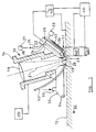
- FIG. 1 this illustrates, partly in section, a preferred form of welding head 10 for a welding apparatus.
- the welding head is shown positioned above the surface 12 of a workpiece to be welded.
- the welding head 10 comprises a housing 14 of aluminium, brass, austenitic stainless steel or other non-magnetic material which supports a focusing means in the form of a lens 16 made for example of optical glass through which a laser beam 18 can be focused on to the workpiece surface 12.
- a plasma welding torch indicated generally by reference 20 which has an electrode 22 surrounded by a plenum chamber 24 to which an inert gas such as argon or helium is supplied under pressure through a tube 26.
- the body of the plasma torch is water cooled (means not shown).
- the plenum chamber 24 terminates at its end adjacent the point of electrode 22 in a water-cooled, interchangeable constricting plasma nozzle 28 ( Figure 7) which is shown schematically.
- the nozzle has a tip 33 which defines a plasma orifice 29in the housing which is positioned beyond the electrode tip.
- a separate chamber 30 is attached to the housing 14 on the opposite side to the plasma torch 20 to which an inert gas is supplied under pressure through a tube 32.
- the separate chamber 30 has an open side of a substantial area covered by a diffuser mesh 34.
- a drive means 23 is provided to cause relative movement of the welding head 10 and the surface 12, as indicated by arrow 36, conveniently by driving the welding head along the workpiece surface 12.
- the laser beam is directed along a first axis 21 through a laser opening 19 in the housing to be focused on the workpiece surface 12.
- a first means in the form of an electrical power source 44 is connected to the electrode 22 and the noble 28 to apply a first signal across the electrode tip and the orifice 28 to strike a pilot arc across these.
- This first electrical signal is a high frequency or impulse, high voltage signal which is merely used to initiate the pilot arc.
- the pilot arc is initiated, it is maintained as a low amperage pilot arc by a second means in the form of a low current dc supply 42.
- the high voltage source 44 initiates the pilot arc using current from the source 42 which then maintains the pilot arc at a lower voltage level.
- a third means in the form of an electrical power source 40 provides either dc or variable polarity current (VPPA) for the main plasma arc.
- VPPA variable polarity current
- the pilot arc is on the whole time the welding apparatus is in use, or awaiting use when the main plasma arc is not being generated.
- the inert gas flows through the plasma nozzle 28, "blowing" the pilot arc outwardly from the nozzle towards the workpiece surface 12.
- the pilot arc ionises the gap between the nozzle and the workpiece surface to provide a conducting path for the main current flow so that when the main power is applied from the electrical source 40 the main plasma arc is formed quite easily.
- the tip of the electrode 22 is positioned "behind" the orifice 29 of the nozzle 28 i.e. the tip of the electrode does not project into the orifice 29.
- the orifice itself is constricted and shaped so as to constrict the plasma arc severely and to create a generally columnar arc which impinges on only a relatively small area of the workpiece surface 12.
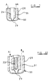
- One example of the plasma nozzle 28 is shown in Figure 7.
- the orifice 29 is generally cylindrical.
- the length/diameter ratio of the orifice 29 is less than 2:1 and is preferably in the range 1.5:1 to 0.5:1, a preferred ratio being 1:1 or 1.2:1.
- the nozzle also has passages 31 for the flow of coolant such as water which flows in the direction of arrows A. This cooling conducts heat away from the nozzle orifice 29 and provides a much longer working life for the nozzle.
- the chamber 24 is preferably formed integral with the housing 14.
- the axis 21 of the laser opening 19 and the axis of the nozzle 28 are aligned such that the laser beam is focused on the workpiece surface at the same location where the constricted plasma arc impinges as a result of which the plasma arc augments the laser heating of the surface 12. Small adjustments may be made to allow pre-set positioning, and the interchangeable orifice can be selected to be of appropriate size and current capacity.
- the laser opening and the plasma nozzle may be arranged to cause the laser beam to focus at a point on the workpiece surface which is spaced from the point of impingement of the constricted plasma arc, if desired.
- the spacing maybe chosen to suit particular welding requirements and materials.
- the above-described arrangement may be used for various types of welding including fusion welding as performed autogenously, homogenously and hetrogenously; braze welding; weld surfacing, and simultaneous reflow welding.
- the coimpingement of the constricted plasma arc and the laser beam focus provides a synergistic heating effect, producing a larger volume of molten weld pool than the sum of the two separate processes.
- a constricting orifice 28 has the advantage of protecting the electrode 22 from metal vapours and other vaporised contaminants, and from the consequential arc instability resulting from electrode contamination.
- the infrequent use of the high voltage, high frequency or impulse current source 42 for starting the pilot arc reduces the extent of etching of the point of electrode 22, resulting in a significantly increased service life compared with TIG arc augmentation welding.
- the use of a pilot arc to initiate the main welding arc provides reliable and controllable conditions for weld start-up.
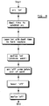
- the sequence of start-up of the plasma arc, laser beam, and welding motion at initiation and termination of welding is critical and should be controlled by a microprocessor, shown schematically at 46.
- the microprocessor may also be used to control the plasma arc operating parameters.
- the operator turns on the inert gas supply to the chamber 24 if not already on, the gas being forced out of the chamber through the orifice 29 and blowing the pilot arc outwardly, in a "bow" effect to assist in the ionising of the surrounding gases.
- the power source 40 is energised to apply a high amperage signal between the electrode tip and the workpiece surface 12 to strike the main plasma arc.
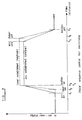
- the current supplied by the power source 40 is allowed to increase in a generally linear fashion from switch on of the power source 40 to the establishment of full plasma arc power at time t 3 .
- plasma arc energy builds up over a period of time to a stable arc condition. This time is normally measured in milliseconds and is chosen normally in dependence on the thickness and type of the material being welded.
- the time t 1 to t 3 is controlled by the microprocessor 46. This control prevents over-penetration and excessive melting of the workpiece material at the start of the weld line.
- the laser is fired.
- the laser energy builds up very rapidly, over a period of microseconds, until the laser attains its maximum energy at time t 4 .
- the laser energy also increases linearly, in a similar manner to that of the plasma arc energy, although the increase in energy of the plasma arc need not be linear.
- the laser rapidly attains an energy level at which complete penetration of the metal workpiece is attained.
- time t 3 and t 4 coincide in time but this need not be the case and the laser can be controlled to reach its preselected energy level either before or after time t 3 .
- Figure 9 shows the laser energy being established at a level above the plasma arc energy and although this is preferred, it is not necessarily always the case and the laser energy can be established at a level below the plasma arc energy level.
- Relative movement of the welding head and the workpiece surface is controlled by the microprocessor to commence when the plasma arc reaches its stable energy level at time t 3 / t 4 , the welding head normally being driven by the drive means 23, although it is possible for the welding head to be maintained stationary and the workpiece to be moved past the welding head.
- Movement of the welding head along the weld line then continues over the time t 3 / t 4 to time t 5 .
- the power supplied by the power source 46 to maintain the plasma arc is reduced. This reduction continues until the arc terminates at time t 7 .
- the time elapsing between times t 5 and t 7 is again measured in milliseconds.
- the laser is switched off, allowing the laser energy to degenerate to zero at time t 7 , this normally occurring in microseconds.
- This controlled termination of the welding process prevents over melting of the metal workpiece and ensures a proper completion of the weld.
- control of the plasma arc and laser are controlled by the microprocessor 46 and enable a consistent weld to be produced.
- the sequence of events and timing of the above-described welding process can vary in dependence on the thickness and type of material being welded and the microprocessor can be provided with predetermined control programmes in dependence on this.
- the inert gas As the surface 12 and the welding head 10 are moved relative to one another, the inert gas
- secondary chamber 30 blankets the hot metal after the plasma augmented laser welding process, preventing oxidation and contamination, and thus helping to ensure a good weld quality.
- the welding head 10 illustrated in Figure 1 has the optional feature of a wire guide 50 through which a consumable wire may be supplied to the surface 12 at the impingement point. This is used in a welding process requiring the supply of a filler metal into the weld pool at the impingement point.
- a second optional feature illustrated in Figure 1 is the provision of magnetic means for deflection of the main plasma arc.
- One or more ferrous metal deflector pole pieces 52 each comprising a metal core closely adjacent the welding torch 20 and orifice 28, are wound with coils 54 to form electromagnets. Only one such pole piece and coil is illustrated. The coils are connected to a current source 55.
- Provision of an electric current of appropriate magnitude, frequency and wave form to the coils 54 generates a magnetic field in the vicinity of the chamber 24 and especially the orifice 28, and this field interacts with the arc, which is a current-carrying gaseous conductor.
- the plasma arc is deflected statically by an amount proportional to the strength of the magnetic field developed in the pole pieces 52 and to the length of the arc.
- An alternating current can cause the arc to oscillate transversely across a weld joint line with an amplitude of deflection determined by the strength of magnetic field and the arc length.
- Oscillation of the arc improves the welding tolerance to fit-up gaps at the weld joint line when butt or seam welding, while maintaining good welding conditions, and is particularly useful in the autogenous welding of sheet-gauge metals. Gaps of up to 30% of the thickness of the sheet material being welded can be tolerated.
- the magnetic oscillation facility provided by coils 54 is particularly useful when joint fit-up conditions are poor, the oscillation of the constricted plasma arc providing additional tolerance.
- the position of the plasma torch 20 is pre-set so that the constricted plasma arc roots on the surface 12 at the point coincident with or in advance of the focus of the laser beam, considering the direction of movement of surface 12.
- Such welds can be made at relatively high speeds, and a chamber 30 is used to provide a trailing gas shield.
- the inert gas protects the weld from atmospheric contamination.
- FIG 2 illustrates a second embodiment of the invention. Parts identical to those in Figure 1 are given identical reference numerals, and the electrical sources are not illustrated.
- a secondary chamber 56 supplied with inert gas through a tube 58 and having a diffuser mesh 60.
- the chamber 56 is positioned on the same side of the head 10 as the plasma torch 20.
- the chamber 56 constitutes a trailing shield for the weld.
- FIG. 3 illustrates a suitable embodiment incorporating a plasma torch 20 and laser beam focusing lens 16 as before, but now supported within a suitably configured housing 62, 64 in a solid weld head 66.
- the head 66 has a conical extension 68 with an aperture 70, at the lower end of which a conical shield gas cup is held by threaded cap 74.
- the internal surface of the cup 72 is coated with a ceramic coating.
- gasket 78 of compliant material such as rubber or neoprene.
- the pressure on the workpiece is sufficient to keep the overlapping parts of two surfaces to be joined in good contact and in close proximity to the plasma arc root. This permits the head to be used for spot welding.
- the shield gas cup 72 is made of a non-magnetic material which has a high thermal conductivity combined with good tensile strength. The cup will then withstand the high temperature and pressure conditions associated with the repeated cycling of spot welding, and the internal ceramic layer reduces the incidence of metal spatter (small globules of molten work metal expelled from the weld pool) adhering to the inside of the cup.
- detachable cup 72 allows it to be replaced periodically.
- the end of the conical extension 68 to which the cup 72 is attached is provided with water cooling. This is to provide satisfactory functional performance and service life of the cup 72.
- Figure 4 shows the head 66, cup 72 and threaded retaining ring 74 attached to the pressure ram 82 of a pneumatic or hydraulic cylinder 84.
- the ram is activated to position the cup 72 on the surface 76, and apply the required pressure, then retract to allow repositioning at the next weld point.
- Such apparatus can be used for spot welding when access to the workpiece is possible from one side only.
- the weld head 66 with its cup 72 is held on a fixed shank 86 attached to the upper part of a "C" frame 88; the lower part of the frame supports a ram 90 carrying a pressure ring 92 by which pressure can be applied upwardly to a workpiece (not shown) positioned between the cup 72, to allow spot welding.
- the weld head 66 with its cup 72 is held on the upper part of a scissor gun 94, and a pressure ring 96 is held on the lower part. Operation of the scissor gun applies pressure to a workpiece between the cup 72 and pressure ring 96.
- Figure 10 shows a modification to the welding head of Figure 1 in which both the laser beam and plasma arc are applied through an orifice of a common nozzle 28.
- the electrode 22 is hollow and the laser beam is focussed down the centre of the electrode, concentric with the plasma arc generated between the tip of the electrode and the workpiece surface.
- a welding head according to the invention may be used whenever carefully controllable welds are required, for example in automated or robotic welding operations, when consistent sequencing and control of the laser beam, plasma arc, and welding motion is essential.
Landscapes
- Engineering & Computer Science (AREA)
- Mechanical Engineering (AREA)
- Physics & Mathematics (AREA)
- Optics & Photonics (AREA)
- Plasma & Fusion (AREA)
- Laser Beam Processing (AREA)
- Arc Welding In General (AREA)
- Lining Or Joining Of Plastics Or The Like (AREA)
- Generation Of Surge Voltage And Current (AREA)
Abstract
Description
wherein the method comprises commencing the welding process by:
and subsequently terminating the welding process by:
- (e) reducing the amperage of said electrical signal at a preselected second rate from said second preselected level until said plasma arc ceases;
- (f) de-energising said laser at a second preselected time after step (e) above; and
- (g) ceasing relative movement between said welding head and said workpiece;
steps (e), (f) and (g) being synchronised such that the cessation of said plasma arc, said laser energy and said relative movement occur at substantially the same time.
- said focussing means focusses said laser beam at a location externally of said housing and on a first axis passing through a laser opening in said housing;
- said electrode extends along an axis of said nozzle means towards said plasma opening for
enabling generation of a constricted plasma arc through said plasma opening between said
electrode and a workpiece to be welded;
wherein said apparatus further comprises: - first means (44) constructed, adapted and arranged to generate a first electrical signal between said nozzle means (28) and said electrode (22) and thereby generate a pilot arc therebetween;
- second means (42) constructed, adapted and arranged to generate a second electrical signal between said electrode (22) and said workpiece (12) and thereby maintain said pilot arc after termination of said first signal;
- third means (40) constructed, adapted and arranged to generate a third electrical signal
between said electrode (22) and said workpiece (12) and thereby strike and establish a main
plasma arc therebetween;
wherein said nozzle means has a tip adapted to constrict said plasma arc thereby to restrict its impingement on said workpiece;
and wherein said first axis and said nozzle means axis are arranged to cause the focussed laser beam and the constricted plasma arc to impinge on said workpiece at predetermined relative positions,
characterised in that the plasma opening is provided in said housing; and in that the apparatus comprises laser firing means constructed, adapted and arranged to fire the laser to reach its desired energy level during or after the establishment of the stable main plasma arc.
Claims (29)
- A method of welding a workpiece (12) using a plasma arc augmented laser welding apparatus having a laser and a welding head (10) wherein the welding head comprises:a plasma torch having a nozzle (28) defining a plasma opening (29) and an electrode (22) disposed inside the torch and extending along the axis of the nozzle towards said opening;first means (44) for applying an electrical signal between said nozzle (28) and said electrode (22) for generating a pilot arc therebetween;means (40) for applying an electrical signal between said electrode (22) and the workpiece (12) for striking a main plasma arc therebetween;and focussing means (16) for focussing the laser beam at the required welding location;
wherein the method comprises commencing the welding process by:wherein steps (a), (b), (c) and (d) are synchronised such that the establishment of the stable plasma arc, the full energising of the laser and the commencement of relative movement of the welding head (10) and the workpiece (12) occur at substantially the same time;(a) applying an electrical signal between said electrode (22) and said workpiece (12) at a predetermined first level sufficient to establish a plasma arc between said electrode (22) and said workpiece (12);(b) increasing the amperage of said signal at a preselected rate up to a second preselected level thereby to establish a stable plasma arc;(c) energising said laser at a pre-selected time after step (a) above and prior to the establishment of a stable plasma arc;(d) commencing relative movement between said welding head (10) and said workpiece (12) so as to cause said welding head (10) to move along a predetermined weld line;
and subsequently terminating the welding process by:(e) reducing the amperage of said electrical signal at a preselected second rate from said second preselected level until said plasma arc ceases;(f) de-energising said laser at a second preselected time after step (e) above; and(g) ceasing relative movement between said welding head (10) and said workpiece (12);
steps (e), (f) and (g) being synchronised such that the cessation of said plasma arc, said laser energy and said relative movement occur at substantially the same time. - A method as claimed in claim 1 which further comprises prior to step (a), the steps of:applying a high voltage electrical signal between the nozzle (28) and the electrode (22) thereby to strike a pilot arc therebetween;and then removing said high voltage electrical signal and applying a low current electrical signal between the electrode (22) and the nozzle (28) thereby to maintain said pilot arc ready for the establishment of a main plasma arc.
- An arc augmented laser welding apparatus having a laser and a welding head (10), the welding head comprising:wherein:a housing (14);focussing means in said housing (14) for focussing a laser beam;a plasma torch (20) having a nozzle means (28) defining a plasma opening (29);and an electrode (22) disposed inside the torch (20);said focussing means focusses said laser beam at a location externally of said housing (14) and on a first axis (21) passing through a laser opening (19) in said housing (14);said electrode extends along an axis of said nozzle means (28) towards said plasma opening (29) for enabling generation of a constricted plasma arc through said plasma opening (29) between said electrode (22) and a workpiece (12) to be welded;
wherein said apparatus further comprises:first means (44) constructed, adapted and arranged to generate a first electrical signal between said nozzle means (28) and said electrode (22) and thereby generate a pilot arc therebetween;second means (42) constructed, adapted and arranged to generate a second electrical signal between said electrode (22) and said workpiece (12) and thereby maintain said pilot arc after termination of said first signal;third means (40) constructed, adapted and arranged to generate a third electrical signal between said electrode (22) and said workpiece (12) and thereby strike and establish a main plasma arc therebetween;
wherein said nozzle means (28) has a tip (33) adapted to constrict said plasma arc thereby to restrict its impingement on said workpiece (12);
and wherein said first axis (21) and said nozzle means (28) axis are arranged to cause the focussed laser beam and the constricted plasma arc to impinge on said workpiece (12) at predetermined relative positions,
characterised in thatthe plasma opening (29) is provided in said housing (14); and in that the apparatus comprises laser firing means constructed, adapted and arranged to fire the laser to reach its desired energy level during or after the establishment of the stable main plasma arc. - A welding apparatus as claimed in claim 3 further comprising control means (46) adapted to control the laser; said first means (44), second means (42) and said third means (40) to cause a sequence of operations in which:(a) the first means (44) applies a high voltage electrical signal between the electrode (22) and the nozzle (28) to strike a pilot arc between them;(b) the means (44) then removes the high voltage signal and the second means (42) applies a low current electrical signal between the electrode (22) and the nozzle (28) to maintain said pilot arc;(c) with the pilot arc maintained, the second means (40) applies a high amperage electrical signal between the electrode (22) and the workpiece to be welded to strike a plasma arc between them;(d) the third means (40) increases the amperage of said signal thereby to establish a stable plasma arc; and(e) the laser is energised to cause the laser beam focussed at the required welding location to reach its required energy level during or after the establishment of the stable plasma arc.
- A welding apparatus as claimed in claim 3 or 4 wherein said predetermined relative positions coincide.
- A welding apparatus as claimed in any of claims 3 to 5 wherein said plasma opening (29) is an orifice forming a restricted opening thereby to protect said electrode (22) from hot metal vapours and gases formed during welding.
- A welding apparatus as claimed in claim 6 wherein said nozzle means (28) is adapted to shape the plasma arc into substantially columnar form.
- A welding apparatus as claimed in claim 6 or 7 wherein said orifice is substantially cylindrical and has an axial length to diameter ratio of less than 2:1.
- A welding apparatus as claimed in claim 8 wherein said length to diameter ratio is in the range 0.5:1.5.
- A welding apparatus as claimed in claim 8 wherein said length to diameter ratio is in the range 1.2:1 to 1:1.
- A welding apparatus as claimed in any of claims 3 to 10 wherein said nozzle means (28) has passages (31) formed therein for the passage of coolant thereby to enable cooling of the nozzle means (28).
- A welding apparatus as claimed in claim 11 wherein said cooling passages (31) extend into the tip (33) of the nozzle means (28) thereby to provide efficient cooling of said tip (33).
- A welding apparatus as claimed in any of claims 3 to 12 having a source (27) of pressurised gas and wherein said nozzle means (28) is adapted to receive said gas and direct said gas outwardly of said nozzle means (28) through said plasma opening (29).
- A welding apparatus as claimed in any of claims 3 to 13 further comprising electromagnetic means (51) adjacent said nozzle means (28) and energisable to deflect said plasma arc in a predetermined manner.
- A welding apparatus as claimed in claim 14 wherein said electromagnetic means (51) has a power source for applying an alternating signal to said electromagnetic means thereby to cause said plasma arc to deflect laterally in an oscillating manner in response to said signal.
- A welding apparatus as claimed in any of claims 3 to 15 wherein said first means (44) is operable to apply a high voltage signal between said electrode (22) and said nozzle means (28) over a preselected period of time thereby to generate said pilot arc and said second means (42) is operable to apply a low current DC signal between said electrode (22) and said nozzle means (28) thereby to maintain said pilot arc.
- A welding apparatus as claimed in any of claims 3 to 16 wherein said third means (40) is operable to apply a high amperage signal between said electrode (22) and said workpiece (12) whereby to generate said main plasma arc therebetween.
- A welding apparatus as claimed in any of claims 3 to 17 wherein said housing (14) is made of a non-magnetic material.
- A welding apparatus as claimed in claim 18 wherein said housing (14) is made of a material selected from the group comprising of aluminium, brass and austenitic stainless steel.
- A welding apparatus as claimed in any of claims 3 to 19 further comprising a chamber (30) coupled to said housing (14) for receiving a supply of inert gas, said chamber being positioned so as to direct said gas over an area adjacent said laser opening (19) and said plasma opening (29) to provide a trailing gas shield for protecting the weld from atmospheric contamination.
- A welding apparatus as claimed in claim 20 wherein said chamber is provided with diffuser means (34) for diffusing said gas over said workpiece (12) adjacent said laser opening (19) and said plasma opening (29).
- A welding apparatus as claimed in any of claims 3 to 21 wherein said plasma opening (29) also serves as said laser opening (19);and said focussing means is adapted to direct said laser beam through said plasma opening (29) substantially coaxially with said plasma arc.
- A welding apparatus as claimed in claim 22 wherein said electrode (22) is cylindrical having an open end adjacent said plasma opening (29);
and wherein said focussing means is adapted to direct said laser beam coaxially through said electrode (22). - A welding apparatus as claimed in any of claims 3 to 21 wherein;said housing (14) is provided with an extension (68) forming said laser opening (19);said nozzle means (28) is positioned within said housing (14) and behind said laser opening (19) whereby said plasma arc is arranged to extend through said laser opening (19);
and wherein an internal surface of said housing extension (68) adjacent said laser opening (19) is provided with a ceramic layer. - A welding apparatus as claimed in claim 24 wherein:said extension (68) is terminated by a frusto-conical cup (72) which has an aperture (73) through which said laser and said plasma arc are directed;and said welding head (10) is resiliently supported for enabling contact of said cup with said workpiece (12) for the welding thereof.
- A welding apparatus as claimed in claim 25 wherein said cup (72) is made of non-magnetic material having a high thermal conductivity.
- A welding apparatus as claimed in claim 26 wherein said cup (72) is detachably mounted on said extension (68).
- A welding apparatus as claimed in claim 25, 26 or 27 wherein said cup (72) has passage means (75) therein for the circulation of coolant.
- A welding apparatus as claimed in any of claims 3 to 28 further comprising microprocessor means (46) for controlling said laser and said first means (44), second means (42) and third means (40) in accordance with a pre-programmed routine.
Applications Claiming Priority (3)
| Application Number | Priority Date | Filing Date | Title |
|---|---|---|---|
| GB9423771 | 1994-11-24 | ||
| GB9423771A GB9423771D0 (en) | 1994-11-24 | 1994-11-24 | Enhanced laser beam welding |
| PCT/GB1995/002739 WO1996015871A1 (en) | 1994-11-24 | 1995-11-24 | Enhanced laser beam welding |
Publications (2)
| Publication Number | Publication Date |
|---|---|
| EP0793558A1 EP0793558A1 (en) | 1997-09-10 |
| EP0793558B1 true EP0793558B1 (en) | 1999-01-20 |
Family
ID=10764944
Family Applications (1)
| Application Number | Title | Priority Date | Filing Date |
|---|---|---|---|
| EP95937101A Revoked EP0793558B1 (en) | 1994-11-24 | 1995-11-24 | Enhanced laser beam welding |
Country Status (12)
| Country | Link |
|---|---|
| US (1) | US5866870A (en) |
| EP (1) | EP0793558B1 (en) |
| JP (1) | JPH11509477A (en) |
| AT (1) | ATE175913T1 (en) |
| AU (1) | AU686475B2 (en) |
| BR (1) | BR9509913A (en) |
| DE (1) | DE69507510T2 (en) |
| DK (1) | DK0793558T3 (en) |
| ES (1) | ES2128781T3 (en) |
| GB (2) | GB9423771D0 (en) |
| GR (1) | GR3029607T3 (en) |
| WO (1) | WO1996015871A1 (en) |
Families Citing this family (60)
| Publication number | Priority date | Publication date | Assignee | Title |
|---|---|---|---|---|
| JP3392683B2 (en) * | 1997-02-10 | 2003-03-31 | 三菱重工業株式会社 | Laser processing head |
| US6191380B1 (en) | 1999-06-16 | 2001-02-20 | Hughen Gerrard Thomas | Plasma arc torch head |
| US6388227B1 (en) * | 1999-07-15 | 2002-05-14 | Plasma Laser Technologies Ltd. | Combined laser and plasma-arc processing torch and method |
| WO2001038038A2 (en) * | 1999-11-19 | 2001-05-31 | Fronius Schweissmaschinen Produktion Gmbh & Co. Kg | Device for a laser hybrid welding process |
| WO2001064591A1 (en) * | 2000-03-01 | 2001-09-07 | Heraeus Amersil, Inc. | Method, apparatus, and article of manufacture for determining an amount of energy needed to bring a quartz workpiece to a fusion weldable condition |
| FR2809646B1 (en) * | 2000-05-31 | 2002-09-27 | Air Liquide | METHOD AND DEVICE FOR HYBRID LASER-ARC WELDING WITH CONTROLLING THE POSITIONING OF MASS TAKES |
| FR2809647B1 (en) * | 2000-05-31 | 2002-08-30 | Air Liquide | HYBRID LASER-ARC WELDING PROCESS WITH APPROPRIATE GAS MIXTURE |
| FR2809645B1 (en) * | 2000-05-31 | 2002-09-27 | Air Liquide | APPLICATION OF A LASER-ARC HYBRID PROCESS TO TUBE WELDING |
| FR2813031B1 (en) * | 2000-08-21 | 2003-01-24 | Air Liquide | HYBRID LASER-ARC WELDING PROCESS AND INSTALLATION USING A POWER DIODE LASER |
| US6483069B2 (en) | 2000-10-02 | 2002-11-19 | The Boeing Company | Joining of structural members by welding |
| DE10128793B4 (en) * | 2001-06-15 | 2005-08-25 | Universität Stuttgart Institut für Strahlwerkzeuge | Method for processing a workpiece with a laser beam |
| FR2829413B1 (en) * | 2001-09-11 | 2003-12-12 | Air Liquide | MULTI-PROCESS MODULAR LASER-ARC HYBRID WELDING TORCH AND INSTALLATION |
| FR2829414B1 (en) * | 2001-09-13 | 2003-10-31 | Air Liquide | HYBRID LASER-ARC WELDING PROCESS WITH GAS FLOW ADJUSTMENT |
| FR2829415B1 (en) * | 2001-09-13 | 2003-10-31 | Air Liquide | METHOD OF STARTING THE ELECTRIC ARC IN HYBRID LASER-ARC WELDING |
| JP3762676B2 (en) * | 2001-09-17 | 2006-04-05 | 本田技研工業株式会社 | Work welding method |
| JP3753656B2 (en) * | 2001-12-27 | 2006-03-08 | 本田技研工業株式会社 | YAG laser and arc combined welding method and apparatus |
| US7408130B2 (en) * | 2002-04-01 | 2008-08-05 | Honda Giken Kogyo Kabushiki Kaisha | YAG laser induced arc filler wire composite welding method and weldimg equipment |
| AU2003237385A1 (en) * | 2002-06-04 | 2003-12-19 | Preco Laser Systems, Llc | High energy beam cladding |
| FR2845023B1 (en) * | 2002-09-26 | 2004-10-29 | Commissariat Energie Atomique | NARROW CHANNEL WELDING INSTALLATION |
| JP4104957B2 (en) * | 2002-11-07 | 2008-06-18 | 日本発条株式会社 | Suspension component joining processing equipment |
| US20040194275A1 (en) * | 2003-04-02 | 2004-10-07 | Dreistern-Werk Maschinenbau Gmbh & Co. Kg | Method and device for the production of a metal profile |
| FR2853269A1 (en) * | 2003-04-04 | 2004-10-08 | Air Liquide | ARC-LASER HYBRID WELDING WITH IMPROVED GAS PROTECTION NOZZLE |
| JP4741478B2 (en) * | 2003-06-03 | 2011-08-03 | イーエスエービー・エービー | Laser welding process control system and method |
| JP2005138223A (en) * | 2003-11-06 | 2005-06-02 | Fanuc Ltd | Positional data correcting device for robot |
| CN100522453C (en) | 2003-12-10 | 2009-08-05 | 菲茨有限责任公司 | Track welding device for pipeline erection |
| CN1298486C (en) * | 2004-07-15 | 2007-02-07 | 北京航空航天大学 | Rotary double focus laser-MIG electric arc composite welding head |
| FR2874624B1 (en) * | 2004-08-30 | 2007-04-20 | Snecma Moteurs Sa | METHOD FOR RECHARGING A MONOCRYSTALLINE OR DIRECTED SOLIDIFICATION METAL PIECE |
| AT501124B1 (en) * | 2004-12-15 | 2007-02-15 | Fronius Int Gmbh | METHOD AND DEVICE FOR COMBINED LASER ARC WELDING |
| US20060213615A1 (en) * | 2004-12-16 | 2006-09-28 | Sematech, Inc. | Laser nozzle cleaning tool |
| US7629556B2 (en) * | 2005-12-16 | 2009-12-08 | Sematech, Inc. | Laser nozzle methods and apparatus for surface cleaning |
| WO2008051252A1 (en) * | 2006-10-24 | 2008-05-02 | Trumpf, Inc. | Moving enclosures for laser equipment |
| DE102007011235A1 (en) * | 2007-03-06 | 2008-09-11 | Plasma Treat Gmbh | Method and device for treating a surface of a workpiece |
| CN101362255B (en) * | 2008-09-11 | 2010-06-09 | 上海交通大学 | Hardness Control Method of Laser Composite Welding Seam of Low Alloy High Strength Steel |
| DE102009020146B3 (en) * | 2009-04-08 | 2010-06-10 | V & M Deutschland Gmbh | Connecting ends of steel tubes by orbital welding in laser-light-arc hybrid technology, comprises connecting tube ends with welding positions, and guiding laser- and light arc welding head as tool over guiding ring during welding process |
| JP5700997B2 (en) * | 2010-10-05 | 2015-04-15 | 川崎重工業株式会社 | Welding head and welding apparatus having the same |
| CN102069305B (en) * | 2011-02-11 | 2012-06-27 | 天津大学 | Laser twin-electric arc compound welding system |
| US20120261459A1 (en) * | 2011-04-12 | 2012-10-18 | Bruck Gerald J | Laser metalworking using reactive gas |
| US20130136940A1 (en) * | 2011-11-28 | 2013-05-30 | General Electric Company | Welding system, welding process, and welded article |
| US9339890B2 (en) | 2011-12-13 | 2016-05-17 | Hypertherm, Inc. | Optimization and control of beam quality for material processing |
| US20140042131A1 (en) * | 2012-08-10 | 2014-02-13 | Lincoln Global, Inc. | Laser welding consumable |
| US20140065320A1 (en) * | 2012-08-30 | 2014-03-06 | Dechao Lin | Hybrid coating systems and methods |
| FR2999461B1 (en) * | 2012-12-19 | 2015-06-26 | Turbomeca | HEAD AND METHOD OF LASER WELDING |
| US20140183167A1 (en) * | 2012-12-28 | 2014-07-03 | Hyundai Motor Company | Welding device for panel sheets and welding method for the same |
| US9790090B2 (en) * | 2013-02-13 | 2017-10-17 | Lawrence Livermore National Security, Llc | Laser-induced gas plasma machining |
| JP2017505236A (en) * | 2014-02-24 | 2017-02-16 | ホウォン カンパニー リミテッド | Hybrid welding machine |
| JP6335602B2 (en) * | 2014-04-14 | 2018-05-30 | 三菱重工業株式会社 | Laser welding method |
| CN105618933B (en) * | 2016-02-19 | 2018-03-16 | 广东省焊接技术研究所(广东省中乌研究院) | Efficient high-quality laser-micro-arc plasma hybrid welding method |
| CN105945430B (en) * | 2016-05-30 | 2017-07-07 | 重庆理工大学 | A kind of low power laser high-efficiency welding method based on micro-beam plasma arc induction |
| WO2018159857A1 (en) * | 2017-03-03 | 2018-09-07 | 古河電気工業株式会社 | Welding method and welding device |
| DE102018205906A1 (en) * | 2018-04-18 | 2019-10-24 | Fraunhofer-Gesellschaft zur Förderung der angewandten Forschung e.V. | Apparatus adapted for laser beam cutting and a method for laser beam cutting |
| CN108581207B (en) * | 2018-07-03 | 2021-03-02 | 哈尔滨工业大学(威海) | A real-time self-adaptive adjustment system and adjustment method of filament spacing for laser-arc hybrid welding |
| JP6852031B2 (en) * | 2018-09-26 | 2021-03-31 | 株式会社東芝 | Welding equipment and nozzle equipment |
| DE102019103659B4 (en) * | 2019-02-13 | 2023-11-30 | Bystronic Laser Ag | Gas guide, laser cutting head and laser cutting machine |
| CZ308592B6 (en) * | 2019-10-21 | 2020-12-16 | Thermacut, K.S. | A part of a cutting or welding torch comprising a thread |
| CN111716003B (en) * | 2020-06-23 | 2022-08-23 | 华北水利水电大学 | Aluminum alloy pulse laser-TIG electric arc composite additive manufacturing device and method |
| US12508775B2 (en) * | 2020-10-15 | 2025-12-30 | Mitsubishi Electric Corporation | Additive manufacturing method, additive manufacturing apparatus, and additive manufacturing system |
| CN115070181B (en) * | 2021-03-16 | 2024-01-05 | 上海梅山钢铁股份有限公司 | Method for improving plasma welding quality |
| CN117600630B (en) * | 2024-01-17 | 2024-04-05 | 锐宝(常州)焊割科技有限公司 | Welding head and welding device for aluminum alloy plasma arc welding |
| CN118768737B (en) * | 2024-08-01 | 2025-07-01 | 北京工业大学 | Thick plate aluminum alloy polarity-changing plasma arc welding method based on laser-assisted perforation |
| CN119237934B (en) * | 2024-09-30 | 2025-09-05 | 华中科技大学 | Laser-MIG composite welding device and method for flexible gun barrel |
Family Cites Families (6)
| Publication number | Priority date | Publication date | Assignee | Title |
|---|---|---|---|---|
| GB1547172A (en) * | 1976-06-24 | 1979-06-06 | Nat Res Dev | Methods and apparatus for cutting welding drilling and surface treating |
| GB1600796A (en) * | 1978-02-15 | 1981-10-21 | Nat Res Dev | Methods and apparatus for cutting welding and surface treating |
| GB2099349B (en) * | 1981-05-28 | 1985-11-06 | Nippon Steel Corp | Laser working process |
| RU1815085C (en) * | 1989-10-25 | 1993-05-15 | Бишкекский политехнический институт | Apparatus for laser-arc machining |
| CN1065420A (en) * | 1991-03-29 | 1992-10-21 | 机械电子工业部哈尔滨焊接研究所 | New-type non-vacuum electronic beam connects method and welding torch |
| US5705785A (en) * | 1994-12-30 | 1998-01-06 | Plasma-Laser Technologies Ltd | Combined laser and plasma arc welding torch |
-
1994
- 1994-11-24 GB GB9423771A patent/GB9423771D0/en active Pending
-
1995
- 1995-11-24 GB GB9524072A patent/GB2295569B/en not_active Expired - Fee Related
- 1995-11-24 ES ES95937101T patent/ES2128781T3/en not_active Expired - Lifetime
- 1995-11-24 US US08/836,973 patent/US5866870A/en not_active Expired - Fee Related
- 1995-11-24 EP EP95937101A patent/EP0793558B1/en not_active Revoked
- 1995-11-24 AU AU39307/95A patent/AU686475B2/en not_active Ceased
- 1995-11-24 DE DE69507510T patent/DE69507510T2/en not_active Revoked
- 1995-11-24 AT AT95937101T patent/ATE175913T1/en not_active IP Right Cessation
- 1995-11-24 DK DK95937101T patent/DK0793558T3/en active
- 1995-11-24 WO PCT/GB1995/002739 patent/WO1996015871A1/en not_active Ceased
- 1995-11-24 BR BR9509913A patent/BR9509913A/en not_active Application Discontinuation
- 1995-11-24 JP JP8516682A patent/JPH11509477A/en active Pending
-
1999
- 1999-03-08 GR GR990400694T patent/GR3029607T3/en unknown
Also Published As
| Publication number | Publication date |
|---|---|
| AU3930795A (en) | 1996-06-17 |
| BR9509913A (en) | 1997-10-14 |
| GB2295569A (en) | 1996-06-05 |
| ATE175913T1 (en) | 1999-02-15 |
| JPH11509477A (en) | 1999-08-24 |
| WO1996015871A1 (en) | 1996-05-30 |
| GB2295569B (en) | 1998-06-10 |
| GR3029607T3 (en) | 1999-06-30 |
| AU686475B2 (en) | 1998-02-05 |
| EP0793558A1 (en) | 1997-09-10 |
| GB9524072D0 (en) | 1996-01-24 |
| DE69507510D1 (en) | 1999-03-04 |
| US5866870A (en) | 1999-02-02 |
| GB9423771D0 (en) | 1995-01-11 |
| DE69507510T2 (en) | 1999-08-12 |
| ES2128781T3 (en) | 1999-05-16 |
| DK0793558T3 (en) | 1999-09-13 |
Similar Documents
| Publication | Publication Date | Title |
|---|---|---|
| US5866870A (en) | Enhanced laser beam welding | |
| CN106163719B (en) | Welding system and method for starting and using combined filler wire feed and high intensity energy for root pass welding of composite pipe inside diameter | |
| US20120234802A1 (en) | Machining Work Pieces with a Laser Apparatus and an Electric Arc Apparatus | |
| US10052707B2 (en) | Method and system to use AC welding waveform and enhanced consumable to improve welding of galvanized workpiece | |
| US9782850B2 (en) | Method and system to start and use combination filler wire feed and high intensity energy source for welding | |
| EP2744619B1 (en) | Method to start and use combination filler wire feed and high intensity energy source for welding | |
| JP6860260B2 (en) | TIG welding torch with constriction nozzle for spot welding and electrode nozzle used for this | |
| US20040238511A1 (en) | Method and apparatus for initiating welding arc with aid of vaporized chemical | |
| US20130327749A1 (en) | Method and system to start and use combination filler wire feed and high intensity energy source for welding aluminum to steel | |
| US9149885B2 (en) | Method and apparatus for the production of a welding seam or a three-dimensional structure on a surface of a metallic work piece | |
| US20030136768A1 (en) | Method and apparatus for composite YAG laser/arc welding | |
| US11731216B2 (en) | Device for working a surface of a workpiece by means of a laser beam and method for operating the device | |
| WO2014009800A2 (en) | Method and system to start and use combination filler wire feed and high intensity source for welding | |
| WO2018145544A1 (en) | Welding torch used for laser beam-plasma arc hybrid welding | |
| Kah et al. | Laser-arc hybrid welding processes | |
| JP4394808B2 (en) | Melt processing equipment using laser beam and arc | |
| RU2668625C1 (en) | Formulated pipe stock butt joint laser-arc welding with consumable electrode method in an atmosphere of shielding gas | |
| JP3973813B2 (en) | Laser arc welding apparatus and method, and laser arc coating method | |
| CZ287455B6 (en) | Welding process and apparatus for making the same | |
| KR100561074B1 (en) | Arc welding device and welding method | |
| JPH0577050A (en) | Torch for tig arc welding and method for pulse tig arc welding | |
| CN121798160A (en) | Handheld laser-electric arc composite welding device | |
| McGee et al. | Gas arc constriction for plasma arc welding | |
| JPH08332570A (en) | TIG welding method |
Legal Events
| Date | Code | Title | Description |
|---|---|---|---|
| PUAI | Public reference made under article 153(3) epc to a published international application that has entered the european phase |
Free format text: ORIGINAL CODE: 0009012 |
|
| 17P | Request for examination filed |
Effective date: 19970502 |
|
| AK | Designated contracting states |
Kind code of ref document: A1 Designated state(s): AT BE CH DE DK ES FR GR IE IT LI LU MC NL PT SE |
|
| GRAG | Despatch of communication of intention to grant |
Free format text: ORIGINAL CODE: EPIDOS AGRA |
|
| 17Q | First examination report despatched |
Effective date: 19971024 |
|
| GRAG | Despatch of communication of intention to grant |
Free format text: ORIGINAL CODE: EPIDOS AGRA |
|
| GRAH | Despatch of communication of intention to grant a patent |
Free format text: ORIGINAL CODE: EPIDOS IGRA |
|
| GRAH | Despatch of communication of intention to grant a patent |
Free format text: ORIGINAL CODE: EPIDOS IGRA |
|
| RBV | Designated contracting states (corrected) |
Designated state(s): AT BE CH DE DK ES FR GR IE IT LI LU MC NL PT SE |
|
| GRAA | (expected) grant |
Free format text: ORIGINAL CODE: 0009210 |
|
| AK | Designated contracting states |
Kind code of ref document: B1 Designated state(s): AT BE CH DE DK ES FR GR IE IT LI LU MC NL PT SE |
|
| PG25 | Lapsed in a contracting state [announced via postgrant information from national office to epo] |
Ref country code: LI Free format text: LAPSE BECAUSE OF NON-PAYMENT OF DUE FEES Effective date: 19990120 Ref country code: CH Free format text: LAPSE BECAUSE OF NON-PAYMENT OF DUE FEES Effective date: 19990120 |
|
| REF | Corresponds to: |
Ref document number: 175913 Country of ref document: AT Date of ref document: 19990215 Kind code of ref document: T |
|
| REG | Reference to a national code |
Ref country code: CH Ref legal event code: EP |
|
| REG | Reference to a national code |
Ref country code: IE Ref legal event code: FG4D |
|
| REF | Corresponds to: |
Ref document number: 69507510 Country of ref document: DE Date of ref document: 19990304 |
|
| ITF | It: translation for a ep patent filed | ||
| REG | Reference to a national code |
Ref country code: CH Ref legal event code: NV Representative=s name: KIRKER & CIE SA |
|
| PG25 | Lapsed in a contracting state [announced via postgrant information from national office to epo] |
Ref country code: DE Free format text: LAPSE BECAUSE OF FAILURE TO SUBMIT A TRANSLATION OF THE DESCRIPTION OR TO PAY THE FEE WITHIN THE PRESCRIBED TIME-LIMIT Effective date: 19990421 |
|
| ET | Fr: translation filed | ||
| REG | Reference to a national code |
Ref country code: ES Ref legal event code: FG2A Ref document number: 2128781 Country of ref document: ES Kind code of ref document: T3 |
|
| REG | Reference to a national code |
Ref country code: DK Ref legal event code: T3 |
|
| PLBQ | Unpublished change to opponent data |
Free format text: ORIGINAL CODE: EPIDOS OPPO |
|
| PLBI | Opposition filed |
Free format text: ORIGINAL CODE: 0009260 |
|
| PGFP | Annual fee paid to national office [announced via postgrant information from national office to epo] |
Ref country code: FR Payment date: 19991109 Year of fee payment: 5 |
|
| PG25 | Lapsed in a contracting state [announced via postgrant information from national office to epo] |
Ref country code: LU Free format text: LAPSE BECAUSE OF NON-PAYMENT OF DUE FEES Effective date: 19991124 Ref country code: IE Free format text: LAPSE BECAUSE OF NON-PAYMENT OF DUE FEES Effective date: 19991124 |
|
| PLBF | Reply of patent proprietor to notice(s) of opposition |
Free format text: ORIGINAL CODE: EPIDOS OBSO |
|
| PG25 | Lapsed in a contracting state [announced via postgrant information from national office to epo] |
Ref country code: SE Free format text: LAPSE BECAUSE OF NON-PAYMENT OF DUE FEES Effective date: 19991125 Ref country code: ES Free format text: LAPSE BECAUSE OF NON-PAYMENT OF DUE FEES Effective date: 19991125 |
|
| PGFP | Annual fee paid to national office [announced via postgrant information from national office to epo] |
Ref country code: DE Payment date: 19991129 Year of fee payment: 5 |
|
| 26 | Opposition filed |
Opponent name: L'AIR LIQUIDE, SOCIETE ANONYME POUR L'ETUDE ET L'E Effective date: 19991005 |
|
| NLR1 | Nl: opposition has been filed with the epo |
Opponent name: L'AIR LIQUIDE, SOCIETE ANONYME POUR L'ETUDE ET L'E |
|
| RDAH | Patent revoked |
Free format text: ORIGINAL CODE: EPIDOS REVO |
|
| RDAG | Patent revoked |
Free format text: ORIGINAL CODE: 0009271 |
|
| REG | Reference to a national code |
Ref country code: CH Ref legal event code: PL |
|
| STAA | Information on the status of an ep patent application or granted ep patent |
Free format text: STATUS: PATENT REVOKED |
|
| EUG | Se: european patent has lapsed |
Ref document number: 95937101.4 |
|
| NLV4 | Nl: lapsed or anulled due to non-payment of the annual fee |
Effective date: 20000601 |
|
| 27W | Patent revoked |
Effective date: 20000420 |
|
| REG | Reference to a national code |
Ref country code: IE Ref legal event code: MM4A |
|
| REG | Reference to a national code |
Ref country code: PT Ref legal event code: MF4A Effective date: 20000830 |