EP0793050A2 - Procédé de garnissage de conduites et appareil destiné à sa mise en oeuvre - Google Patents
Procédé de garnissage de conduites et appareil destiné à sa mise en oeuvre Download PDFInfo
- Publication number
- EP0793050A2 EP0793050A2 EP97301280A EP97301280A EP0793050A2 EP 0793050 A2 EP0793050 A2 EP 0793050A2 EP 97301280 A EP97301280 A EP 97301280A EP 97301280 A EP97301280 A EP 97301280A EP 0793050 A2 EP0793050 A2 EP 0793050A2
- Authority
- EP
- European Patent Office
- Prior art keywords
- skirt
- pipeline
- lining
- tapered
- outward
- Prior art date
- Legal status (The legal status is an assumption and is not a legal conclusion. Google has not performed a legal analysis and makes no representation as to the accuracy of the status listed.)
- Withdrawn
Links
Images


Classifications
-
- F—MECHANICAL ENGINEERING; LIGHTING; HEATING; WEAPONS; BLASTING
- F16—ENGINEERING ELEMENTS AND UNITS; GENERAL MEASURES FOR PRODUCING AND MAINTAINING EFFECTIVE FUNCTIONING OF MACHINES OR INSTALLATIONS; THERMAL INSULATION IN GENERAL
- F16L—PIPES; JOINTS OR FITTINGS FOR PIPES; SUPPORTS FOR PIPES, CABLES OR PROTECTIVE TUBING; MEANS FOR THERMAL INSULATION IN GENERAL
- F16L55/00—Devices or appurtenances for use in, or in connection with, pipes or pipe systems
- F16L55/26—Pigs or moles, i.e. devices movable in a pipe or conduit with or without self-contained propulsion means
- F16L55/28—Constructional aspects
-
- F—MECHANICAL ENGINEERING; LIGHTING; HEATING; WEAPONS; BLASTING
- F16—ENGINEERING ELEMENTS AND UNITS; GENERAL MEASURES FOR PRODUCING AND MAINTAINING EFFECTIVE FUNCTIONING OF MACHINES OR INSTALLATIONS; THERMAL INSULATION IN GENERAL
- F16L—PIPES; JOINTS OR FITTINGS FOR PIPES; SUPPORTS FOR PIPES, CABLES OR PROTECTIVE TUBING; MEANS FOR THERMAL INSULATION IN GENERAL
- F16L55/00—Devices or appurtenances for use in, or in connection with, pipes or pipe systems
- F16L55/16—Devices for covering leaks in pipes or hoses, e.g. hose-menders
- F16L55/162—Devices for covering leaks in pipes or hoses, e.g. hose-menders from inside the pipe
- F16L55/164—Devices for covering leaks in pipes or hoses, e.g. hose-menders from inside the pipe a sealing fluid being introduced in the pipe
Definitions
- This invention relates to methods of lining conduits, for example pipes, and especially water pipes, and apparatus for applying the same.
- a winch wire is passed through the pipeline (and mortar) and a fixed dimensioned metal tapered skirt is attached to the end of the wire at the mortar filled end of the wire and to a winch at the opposite end.
- the skirt (which at its trailing end is say 1 inch in diameter less than the pipeline) was drawn by a winch through the line, the tapered skirt during its axial travel naturally providing a pressure in its peripheral gap with the pipe, squeezing outwardly the mortar and filling gaps in the pipe wall and leaving a lined pipe behind it.
- Leakage is now a primary area of concern, since it is known to be the case that 80% of current-day water loss stems directly from the type of leak path to which at least some of the above mentioned earlier tapered skirt systems are directed.
- a method of providing a hardenable lining to a pipeline having a leakage problem comprising injecting into a length of the pipeline a plug of suitable hardenable material and passing through the pipeline from the end containing a majority of the hardenable material a skirt shaped member radially outwardly tapered in the downstream direction the trailing edge of the skirt having been adjusted to provide a predetermined annular gap with the internal wall of the pipeline.
- apparatus for providing a hardenable lining to a pipeline having a leakage problem comprising a tapered skirt device and means for moving same through the pipeline, the skirt device being arranged in use to engage with a plug of hardenable material injected into the pipeline and move upstream with respect to the outward tapering skirt, whereby to press the plug against the internal walls of the pipeline the skirt device having associated means for varying its radial diameter at its outward tapered end.
- a predetermined lining thickness may be provided for the pipeline.
- depressions in the internal pipe wall, at joints and holes and other irregularities may be provided with extra lining to prevent leakage.
- the suitable hardenable material may comprise any suitable material, such as a cement/mortar mix, or a polymerised cement mortar mix.
- the invention may include means for varying the diameter of the downstream edge of the skirt during lining of a pipeline.
- the invention can ensure that when, during the passage of the tapered cones through the pipeline and the included slug of cement mortar, for example, passes any form of gap or depressive irregularity, the angle of the cone and the peripheral force contained within the cement mortar can combine to force mortar, into, through, and to fill gaps, holes at interstices, for example, to prevent leakage. It is to be noted that to have a skirt peripheral gap at the outermost portion of the tapered skirt, of the correct dimension relative to the pipe diameter is, to achieve the above mentioned advantage, of importance.
- the invention provides the ability to produce thin, consistent thickness of pipe lining.
- skirt 1 of a polyurethane or similar rubber/polymer of hard wearing quality which is extendable to a degree, formed or moulded to produce a hollow tapered skirt.
- the dimension of its greater diameter is slightly less (say 1 ⁇ 4") than the desired diameter of the finished diameter of a finally lined pipe (not shown).
- the skirt is formed to a given diameter pipe (4" for example).
- a metal cone 2 (Figure 2) of a similar taper angle to the skirt 1 is placed partially within the skirt 1.
- FIG 5 there is shown diagrammatically a hydro/pneumatic insert to the skirt with a fluid inlet and outlet 11.
- the insert 8 may be hydro-pneumatically controlled.
- FIG. 6 another arrangement comprises a hollow skirt 10 which may itself be pressurised and increased or reduced in diameter.
- Figure 7 there is shown a further arrangement of a hollow-walled skirt 9 together with a metal insert 12 where both modes of adjustment discussed above can be employed.
- Figure 8 there is shown a skirt device as of any of the previously described designs for an adjustable skirt in which the actual skirt is formed from thin metal overlapping leaves 13 and may be actuated in effect similar to an Iris.
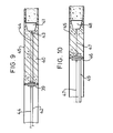
- a plunger 39 is positioned in front of the mortar slug 40 and as lining proceeds, it is progressively moved closer to skirt 41 thereby maintaining complete slug fill of pipe 45 in front of the skirt.
- the movement of the plunger 39 is effected by an adjuster wire 42 which acts through a turn block 43 progressively to reduce the length of twin wire 44 between the skirt 41 and the travelling plunger 39.
- FIG. 10 Another containment system is shown in Figure 10 where a plunger 46 is fixed to the tow wire 47 in a fixed position (say 1m) from skirt 48.
- the void between the plunger 46 and the skirt 48 is kept full of mortar during lining by replenishment of any used amount via a mortar feed tube 49, based on prior calculation.
- skirt may be desirable in all arrangements of skirt hereinbefore described to use a second skirt in tandem with the single skirt previously illustrated on an either/or basis.
- Arrangements may be provided for remote control of the skirt device trailing edge diameter in the context of the relevant pipe measuring device.
- the device automatically measures the pipe diameter as it proceeds through the pipeline during the lining operation.
- This device may be fixed with respect to the skirt towing wire at a predetermined position in front of the skirt, say three to twenty feet.
- the measuring mechanism may be designed in a way to trigger automatically a force or signal to a mechanism in the skirt which increases or decreases the skirt diameter directly in relation to the measured diameters found by the measuring device during its travel through the lining section so as to achieve a lining thickness of substantially constant dimension regardless of the pipe diameter encountered.
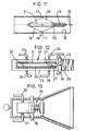
- Figure 11 illustrates a measuring device 14, towed in the direction of arrow 19 which triggers a fluid pressure to the skirt (not shown) which in turn alters the skirt diameter to suit any found diameter.
- the diameter sensing actuating mechanism is in the form of an umbrella-like device actuating an open and close mechanism.
- Compression spring 15 holds, via pivot arms 16, pivot skids 17 in contact with the pipe inner wall 18.
- a sliding pivot 20 moves along a barrel 21 either from the spring force acting to keep the pivot skid 17 in contact with the pipe wall 18 in enlarged diameter or from the pivot skid 17 forcing the sliding pivot 20 to compress the spring 15 in reduced diameter.
- Figure 12 illustrates a mechanism 22 which can replace part of the barrel 21 of Figure 11 and which resembles a ball cock valve but not only allows fluid to flow through or stop but also allows flow through, stop and exhaust.
- This valve is situated in barrel 23 and actuated from sliding pivot 24.
- the control rod 25 is actuated by sliding pivot 24 when diameter changes occur.
- a fluid inlet 26 allows fluid to move through the inlet porting 27 into supply pipe 28 to the skirt (not shown) .
- sliding pivot 24 moves against spring 29 and draws valve piston 30 within valve cylinder 31 to close the inlet porting 27 and open exhaust porting 32 and so release fluid from the skirt via pipes 33 and 34.
- Figure 13 illustrates a mechanism which could be employed to work in conjunction with the arrangement of Figure 12 used to control for example the arrangements of Figures 5 to 7.
- the device or adjuster 35 would be in the form of a pneumatic/hydraulic ram 36 with simple couple for inlet/exhaust pipes 37, 38 from pipes 28, 38 of Figure 12.
Landscapes
- Engineering & Computer Science (AREA)
- General Engineering & Computer Science (AREA)
- Mechanical Engineering (AREA)
- Chemical & Material Sciences (AREA)
- Combustion & Propulsion (AREA)
- Lining Or Joining Of Plastics Or The Like (AREA)
- Pipe Accessories (AREA)
Applications Claiming Priority (2)
| Application Number | Priority Date | Filing Date | Title |
|---|---|---|---|
| GBGB9604091.0A GB9604091D0 (en) | 1996-02-27 | 1996-02-27 | Methods of lining conduits and apparatus for applying the same |
| GB9604091 | 1996-02-27 |
Publications (2)
| Publication Number | Publication Date |
|---|---|
| EP0793050A2 true EP0793050A2 (fr) | 1997-09-03 |
| EP0793050A3 EP0793050A3 (fr) | 1999-06-16 |
Family
ID=10789459
Family Applications (1)
| Application Number | Title | Priority Date | Filing Date |
|---|---|---|---|
| EP97301280A Withdrawn EP0793050A3 (fr) | 1996-02-27 | 1997-02-26 | Procédé de garnissage de conduites et appareil destiné à sa mise en oeuvre |
Country Status (2)
| Country | Link |
|---|---|
| EP (1) | EP0793050A3 (fr) |
| GB (1) | GB9604091D0 (fr) |
Cited By (2)
| Publication number | Priority date | Publication date | Assignee | Title |
|---|---|---|---|---|
| EP1773510A4 (fr) * | 2004-06-18 | 2007-10-24 | Plastocor Inc | Systeme et procede de chemisage de tubes |
| US11235347B2 (en) | 2015-07-10 | 2022-02-01 | Plastocor, Inc. | System and method for coating tubes |
Family Cites Families (3)
| Publication number | Priority date | Publication date | Assignee | Title |
|---|---|---|---|---|
| US3990830A (en) * | 1975-04-07 | 1976-11-09 | Ameron, Inc. | Multi-stage trowel for smoothing pipe lining material |
| US4252763A (en) * | 1978-06-06 | 1981-02-24 | Raymond International Builders, Inc. | Method and apparatus for cement lining of pipes |
| FR2517222B2 (fr) * | 1980-12-11 | 1986-03-21 | Diga Die Gasheizung Gmbh | Dispositif en forme de mandrin pour revetir la paroi interieure de conduits tubulaires |
-
1996
- 1996-02-27 GB GBGB9604091.0A patent/GB9604091D0/en active Pending
-
1997
- 1997-02-26 EP EP97301280A patent/EP0793050A3/fr not_active Withdrawn
Cited By (4)
| Publication number | Priority date | Publication date | Assignee | Title |
|---|---|---|---|---|
| EP1773510A4 (fr) * | 2004-06-18 | 2007-10-24 | Plastocor Inc | Systeme et procede de chemisage de tubes |
| US7717056B2 (en) | 2004-06-18 | 2010-05-18 | Plastocor, Inc. | System and method for coating tubes |
| US8359996B2 (en) | 2004-06-18 | 2013-01-29 | Plastocor, Inc. | System and method for coating tubes |
| US11235347B2 (en) | 2015-07-10 | 2022-02-01 | Plastocor, Inc. | System and method for coating tubes |
Also Published As
| Publication number | Publication date |
|---|---|
| EP0793050A3 (fr) | 1999-06-16 |
| GB9604091D0 (en) | 1996-05-01 |
Similar Documents
| Publication | Publication Date | Title |
|---|---|---|
| US6024910A (en) | Method for lining a tubular conduit | |
| CA2050029A1 (fr) | Methode pour le garnissage des surfaces interieures des canalisations | |
| US4401696A (en) | Lining of pipelines and passageways | |
| US7707704B2 (en) | Sealing methods | |
| DE2249256A1 (de) | Verfahren zum anbringen einer beschichtung auf der innenwand eines rohres | |
| CN112878163B (zh) | 一种沥青路面灌缝装置和方法 | |
| CA1088494A (fr) | Methode et dispositif pour interrompre l'ecoulement dans un tube | |
| EP0793050A2 (fr) | Procédé de garnissage de conduites et appareil destiné à sa mise en oeuvre | |
| GB2082285A (en) | Lining Passageways | |
| GB2225406A (en) | Methods and apparatus for use in pipe lining. | |
| US5779948A (en) | Method of lining a pipeline using a constant extrusion pressure | |
| GB2536022A (en) | Applicator device | |
| US5992467A (en) | Liner reduction system using pressurized dies and apparatus therefor | |
| DE3931775A1 (de) | Geraet zum beschichten von innenflaechen einer abwasserrohrleitung | |
| GB2274699A (en) | Lining pipes | |
| EP0761417B1 (fr) | Procédé de réparation d'une tuyauterie | |
| CN217595063U (zh) | 活塞式内壁涂油装置 | |
| JP3586325B2 (ja) | 管内塗装装置 | |
| JPS5850779B2 (ja) | パイプの内面ライニング法 | |
| JP2977602B2 (ja) | 管路内面のライニング方法 | |
| CN216978282U (zh) | 一种给水管网漏损定位装置 | |
| RU213823U1 (ru) | Устройство для нанесения защитно-декоративного покрытия на внутреннюю поверхность труб | |
| JPH08131924A (ja) | 既設管の内面ライニング装置 | |
| JP2900199B2 (ja) | 異径管の内面ライニング補修工法 | |
| JP2665920B2 (ja) | 管内面のライニング補修工法 |
Legal Events
| Date | Code | Title | Description |
|---|---|---|---|
| PUAI | Public reference made under article 153(3) epc to a published international application that has entered the european phase |
Free format text: ORIGINAL CODE: 0009012 |
|
| AK | Designated contracting states |
Kind code of ref document: A2 Designated state(s): AT BE DE FR GB IE IT NL |
|
| PUAL | Search report despatched |
Free format text: ORIGINAL CODE: 0009013 |
|
| RIN1 | Information on inventor provided before grant (corrected) |
Inventor name: LIPPIATT, RAYMOND |
|
| AK | Designated contracting states |
Kind code of ref document: A3 Designated state(s): AT BE DE FR GB IE IT NL |
|
| RAP1 | Party data changed (applicant data changed or rights of an application transferred) |
Owner name: EVOLVED PROCESSES LIMITED |
|
| RIC1 | Information provided on ipc code assigned before grant |
Free format text: 6F 16L 55/162 A, 6F 16L 55/26 B, 6B 05C 7/08 B, 6B 28B 19/00 B |
|
| STAA | Information on the status of an ep patent application or granted ep patent |
Free format text: STATUS: THE APPLICATION IS DEEMED TO BE WITHDRAWN |
|
| 18D | Application deemed to be withdrawn |
Effective date: 19991217 |