EP0792452B1 - Appareil lumineux pour inspection de surface - Google Patents
Appareil lumineux pour inspection de surface Download PDFInfo
- Publication number
- EP0792452B1 EP0792452B1 EP95936658A EP95936658A EP0792452B1 EP 0792452 B1 EP0792452 B1 EP 0792452B1 EP 95936658 A EP95936658 A EP 95936658A EP 95936658 A EP95936658 A EP 95936658A EP 0792452 B1 EP0792452 B1 EP 0792452B1
- Authority
- EP
- European Patent Office
- Prior art keywords
- light
- region
- intensity
- function
- imaginary line
- Prior art date
- Legal status (The legal status is an assumption and is not a legal conclusion. Google has not performed a legal analysis and makes no representation as to the accuracy of the status listed.)
- Expired - Lifetime
Links
- 238000007689 inspection Methods 0.000 title claims abstract description 15
- 230000007547 defect Effects 0.000 claims abstract description 45
- 238000011179 visual inspection Methods 0.000 claims abstract description 9
- 239000003973 paint Substances 0.000 claims description 8
- 230000000007 visual effect Effects 0.000 claims description 6
- 238000002310 reflectometry Methods 0.000 claims description 2
- 230000006870 function Effects 0.000 description 18
- 238000003491 array Methods 0.000 description 6
- 210000004556 brain Anatomy 0.000 description 2
- 238000010586 diagram Methods 0.000 description 2
- 230000000873 masking effect Effects 0.000 description 2
- 230000008447 perception Effects 0.000 description 2
- 230000005855 radiation Effects 0.000 description 2
- NIXOWILDQLNWCW-UHFFFAOYSA-N acrylic acid group Chemical group C(C=C)(=O)O NIXOWILDQLNWCW-UHFFFAOYSA-N 0.000 description 1
- 230000001419 dependent effect Effects 0.000 description 1
- 230000000694 effects Effects 0.000 description 1
- 238000001914 filtration Methods 0.000 description 1
- 230000012447 hatching Effects 0.000 description 1
- 238000003384 imaging method Methods 0.000 description 1
- 239000000463 material Substances 0.000 description 1
- 238000000034 method Methods 0.000 description 1
- 229920003023 plastic Polymers 0.000 description 1
- 229920000728 polyester Polymers 0.000 description 1
Images


Classifications
-
- G—PHYSICS
- G01—MEASURING; TESTING
- G01N—INVESTIGATING OR ANALYSING MATERIALS BY DETERMINING THEIR CHEMICAL OR PHYSICAL PROPERTIES
- G01N21/00—Investigating or analysing materials by the use of optical means, i.e. using sub-millimetre waves, infrared, visible or ultraviolet light
- G01N21/84—Systems specially adapted for particular applications
- G01N21/88—Investigating the presence of flaws or contamination
- G01N21/8803—Visual inspection
-
- G—PHYSICS
- G01—MEASURING; TESTING
- G01N—INVESTIGATING OR ANALYSING MATERIALS BY DETERMINING THEIR CHEMICAL OR PHYSICAL PROPERTIES
- G01N21/00—Investigating or analysing materials by the use of optical means, i.e. using sub-millimetre waves, infrared, visible or ultraviolet light
- G01N21/84—Systems specially adapted for particular applications
- G01N21/88—Investigating the presence of flaws or contamination
- G01N21/8806—Specially adapted optical and illumination features
-
- G—PHYSICS
- G01—MEASURING; TESTING
- G01N—INVESTIGATING OR ANALYSING MATERIALS BY DETERMINING THEIR CHEMICAL OR PHYSICAL PROPERTIES
- G01N21/00—Investigating or analysing materials by the use of optical means, i.e. using sub-millimetre waves, infrared, visible or ultraviolet light
- G01N21/84—Systems specially adapted for particular applications
- G01N21/88—Investigating the presence of flaws or contamination
- G01N21/95—Investigating the presence of flaws or contamination characterised by the material or shape of the object to be examined
- G01N21/9515—Objects of complex shape, e.g. examined with use of a surface follower device
Definitions
- This invention relates to a lighting apparatus for visual inspection for defects of a reflective surface.
- a wide range of manufactured products are visually inspected by human inspectors in order to locate and assess surface defects.
- a surface For effective inspection a surface must be illuminated in such a way that significant defects can be easily seen and distinguished from other features.
- the characteristics of the light such as its intensity and direction, strongly affect the inspection performance.
- the present invention is distinct from the Mazda patent in that the present invention is directed exclusively towards human visual inspection, and not towards automatic inspection.
- the distribution of light from the present invention is specific to human visual inspection, so the present invention would be inappropriate for automatic inspection.
- the present invention seeks to provide an apparatus which is less subject to these drawbacks.
- a surface inspection lighting apparatus for use in the visual inspection by a human inspector of a reflective test surface for surface defects, having a region from which light emanates when the apparatus is in use, the intensity of the light emanating from the said region varying gradually substantially as an exponential function of a sinusoidal function of the distance along an imaginary line across the said region, so that the specular reflection of light from said region in a flat, defect free, reflective test surface is perceived by a human inspector to have a substantially sinusoidal intensity distribution.
- test surface acts as a mirror and the inspector perceives a smooth, sinusoidal intensity distribution and can judge that the surface is of good quality.
- a surface defect on a reflective surface typically distorts the level of the surface. Light specularly reflected by the defect is therefore reflected in a direction different from that of the light reflected by the good quality surface that surrounds it.
- the inspector views the reflection of the apparatus in the test surface, at the location of the defect he sees light reflected from a position on the apparatus that is remote from the positions on the apparatus from which light is reflected to the inspector by the good quality surface surrounding the defect.
- the defect is perceived to have an intensity different to that of its surrounding area. If the severity and size of the defect are sufficient the inspector sees a sharp change in the intensity at the location of the defect and this can be distinguished from the gradual changes in the intensity due to the spatial pattern of the apparatus.
- the human visual/perceptual system is sensitive both to step changes in light intensity within a field of view, and to step changes in light intensity gradient. A person therefore easily perceives visual features of this kind.
- the visual/perceptual system is relatively insensitive to slow, gradual changes of intensity or intensity gradient, so a person does not readily perceive features of these kinds.
- signal processing terms it appears that the human eye/brain system carries out a kind of automatic filtering operation that passes features of high spatial frequency and allows them to be perceived, but cuts out low spatial frequency features so that they are generally ignored.
- a pattern of light with a sinusoidal distribution of intensity has neither sharp intensity changes nor sharp changes in intensity gradient (nor, indeed, sharp changes in any higher order differentials).
- Such a pattern, with a sufficiently long wavelength of sine wave is therefore effectively 'filtered out' by the human perception system, allowing attention to be readily given to small features corresponding to surface defects.
- the intensity of light perceived by a human is substantially a logarithmic function of the actual light intensity.
- a person judges a small change in a low light intensity to be of similar magnitude to a large change in a high light intensity.
- the actual light distribution should be an exponential function of a sine wave, so that the exponential function acts as the inverse of the logarithmic perception function.
- a light distribution which approximates well to the ideal distribution described above can be produced by one or more light source(s) covered with a diffuser panel.
- the light emanating from the diffuser panel is made to conform to the required light distribution by masking it with a computer generated printed pattern, applied on the side of the apparatus facing away from the light source(s).
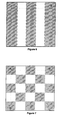
- the spatial pattern of light intensity can take a number of forms.
- the pattern is in the form of linear, parallel, alternating dark and bright bands.
- the distribution can be a pattern of tiled, or tessellated, polygons such as triangles, squares or hexagons. In each case, however, the distribution of light intensity across the band or tile is an exponential function of a sinusoidal function of the distance across the said region.
- the apparatus can advantageously be used for the visual inspection of painted vehicle bodies for paint and other defects.
- a number of units of the apparatus may be configured as a planar array.
- a vertical array may form a wall, while a generally horizontal array may form a ceiling.
- These walls are typically positioned facing each other, on opposite sides of the vehicle body under inspection.
- a generally horizontal ceiling array may be added to form an arch, or positioned separately as a stand alone array.
- the arrays can also be configured to give a wall on its own, or a single wall in conjunction with a ceiling array.
- a ceiling array alone could be employed where inspection is for generally horizontal surfaces only.
- the apparatus is a light box with a diffuser panel over its front and a printed pattern applied to the front of the diffuser.
- the light box 1 is positioned such that the eye of the inspector 2 sees the specular reflection of the light box in the painted surface 3.
- the painted surface can, for example, be part of the bonnet of a painted car body.
- One of the light paths 4 from the light box to the inspector via a good quality area of the painted surface is shown as a solid line.
- a light path 5, from the light box to the inspector via a defect 6, is shown as a dashed line. This illustrates how light is deflected by the defect.
- Figure 2 shows a horizontal cross-section of the light box through the line A-B.
- the light box comprises an open fronted box 7 in which is mounted one or more vertical parallel white fluorescent lamp(s) 8.
- a white acrylic diffuser panel 9 is fixed over the front of the box and in front of the diffuser is a mask, in the form of a sheet 10 of transparent plastics material, for example polyester, onto which is printed a computer generated pattern.
- This pattern comprises a myriad of black dots of varying sizes on unprinted background, or black print with a myriad of dots of varying sizes where there is no print, as with black and white printed graphical newspaper images.
- the density of the print is an approximation to the exponential of a sinusoidal distribution, weighted to account for the natural distribution of light from the lamp(s) through the diffuser.
- the intensity of light produced is high. At other points across the front of the apparatus the light intensity is reduced both by the greater distance from the lamps and the effect of the masking pattern.
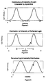
- the light intensity I as a function of distance x along the line A-B is a wave-like distribution in which the light intensity changes smoothly between dark and bright.
- the distribution is weighted towards the dark, i.e. the majority of the width of the distribution is less than half the maximum intensity.
- the light intensity at the darkest parts of the distribution is substantially zero.
- the light intensity at the points half way between the centres of adjacent bright and dark bands is substantially 12% of the maximum intensity.
- the light intensity that is perceived by the human eye/brain system is a logarithmic function of the actual intensity of light arriving at the eye.
- the distribution of light perceived by the inspector along line C-D, shown in Figure 5, is modified from the actual distribution by a logarithmic function.
- the inspector therefore perceives a sinusoidal light distribution, with gently changing light intensity, except at the location of the defect, where he sees a sharp change in brightness. He can therefore readily identify the defect.
- Variations on the pattern shown in Figure 3 can be used to give the desired results, in terms of the visibility of specific defect types.
- the pattern wavelength L (the distance from the centre of a bright band to the centre of the adjacent bright band) of the pattern is short in relation to the distance of the light box from the painted surface, defects of low severity are visible.
- a longer pattern wavelength is used in order that low severity defects, such as orange peel, are not visible, while more severe defects like dirt can clearly be seen. This means that only the defects which can and should be repaired are visible, so that the amount of visual information is reduced and the inspector can carry out his task more effectively.
- defects of greater severity appear to have greater contrast, and can therefore be distinguished from defects of lower severity. This facilitates the inspector's decision of whether a defect is severe enough to need to be repaired.
- a pattern of tessellated squares can be used, as shown in Figure 7.
- the hatched parts of the diagram indicate the areas that appear dark, while the unhatched parts are those areas that appear bright.
- the hatching itself is not part of the pattern.
- the distribution of light along the imaginary line A-B shown in each of Figures 1, 6 and 7 is as shown in Figure 3.
- FIG. 8 An example of the configuration of the apparatus for the inspection of a painted car body is shown in Figure 8.
- Multiple light boxes 1 are stacked to form two vertical arrays, each three light boxes high.
- the arrays can also be extended in the horizontal direction, parallel to the side of the car body, to give additional coverage along the length of the car body.
- the arrays are positioned respectively on opposite sides of the car body 11 to be inspected, with the light emanating surfaces facing each other.
- the inspector stands between the wall and the car body, viewing the reflection of the walls in the surface of the painted car body.
Landscapes
- Physics & Mathematics (AREA)
- Health & Medical Sciences (AREA)
- Life Sciences & Earth Sciences (AREA)
- Chemical & Material Sciences (AREA)
- Analytical Chemistry (AREA)
- Biochemistry (AREA)
- General Health & Medical Sciences (AREA)
- General Physics & Mathematics (AREA)
- Immunology (AREA)
- Pathology (AREA)
- Investigating Materials By The Use Of Optical Means Adapted For Particular Applications (AREA)
- Switches Operated By Changes In Physical Conditions (AREA)
- Spinning Or Twisting Of Yarns (AREA)
Claims (10)
- Appareil d'éclairage pour inspection de surface, destiné à être utilisé dans l'inspection visuelle, par un inspecteur humain, d'une surface réfléchissante pour y déceler des défauts de surface, comportant une zone d'où émane de la lumière lorsque l'appareil est en cours d'utilisation,
l'appareil comprenant
des moyens (10) pour faire varier progressivement l'intensité de la lumière émanant de la zone, essentiellement suivant une fonction exponentielle d'une fonction sinusoïdale de la distance suivant une ligne imaginaire passant par la zone, de façon que la réflexion spéculaire de la lumière provenant de la zone dans une surface de test réfléchissante plate et sans défauts, soit perçue par un inspecteur humain comme ayant une distribution d'intensité essentiellement sinusoïdale. - Appareil selon la revendication 1,
dans lequel
l'intensité de la lumière émanant de la zone sous la forme d'une fonction de la distance le long d'une ligne imaginaire passant par la zone, est donnée par l'équation :dans laquelle :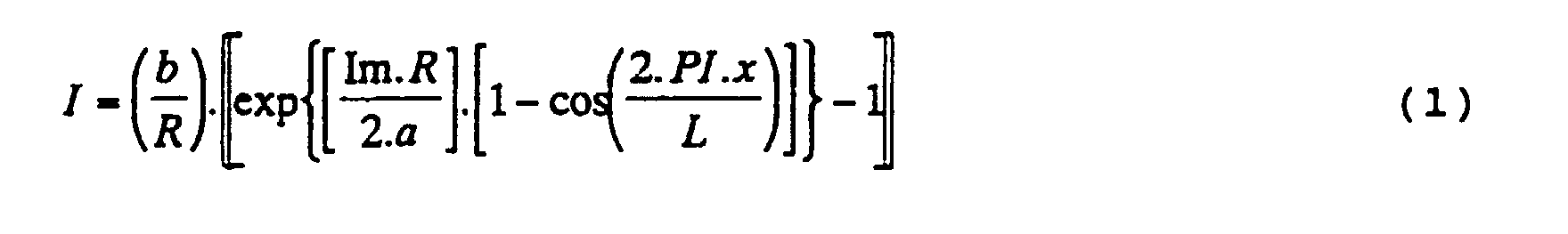
- exp
- indique la fonction exponentielle ;
- I =
- intensité de la lumière ;
- b =
- constante dérivée de la réponse du système visuel humain à l'intensité de la lumière ;
- R =
- pouvoir réflecteur de la peinture, c'est-à-dire proportion de la lumière incidente qui est réfléchie spéculairement ;
- Im =
- intensité maximum de la lumière ;
- PI =
- rapport de la circonférence d'un cercle à la longueur de son diamètre ;
- L =
- longueur d'onde, c'est-à-dire distance entre les centres de bandes lumineuses adjacentes ;
- x =
- distance à partir du bord de l'appareil, le long
d'une ligne imaginaire passant par la zone ; et
- Appareil selon la revendication 1 ou la revendication 2,
dans lequel
la variation de l'intensité de la lumière émanant de la zone, a une configuration spatiale qui se présente sous la forme de bandes linéaires parallèles alternativement brillantes et noires. - Appareil selon la revendication 1 ou la revendication 2,
dans lequel
la variation de l'intensité de la lumière émanant de la zone, a une configuration spatiale qui se présente sous la forme de polygones en mosaïque. - Appareil selon l'une quelconque des revendications précédentes,
dans lequel
la lumière est produite par une ou plusieurs sources de lumière, puis cette lumière est diffusée par un panneau diffuseur et masquée ensuite partiellement par un motif imprimé. - Appareil selon la revendication 5,
dans lequel
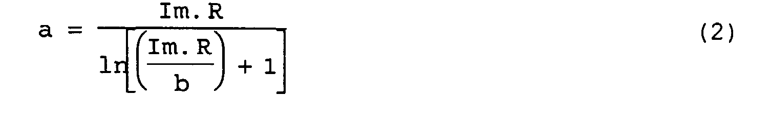
la densité de l'impression du motif imprimé en fonction de la distance suivant une ligne imaginaire passant par la zone, est donnée par l'équation :dans laquelle :
- D =
- densité de l'impression du motif imprimé ;
- I =
- distribution de l'intensité lumineuse telle qu'elle est définie dans la revendication 2 ;
- In =
- distribution de l'intensité lumineuse naturelle de la source de lumière à travers le diffuseur non masqué, cette distribution étant mesurée empiriquement par balayage d'un compteur de lumière en travers de la surface avant du diffuseur non masqué.
- Appareil selon l'une quelconque des revendications précédentes,
assemblé pour former un ou plusieurs réseaux plans dans l'une quelconque des configurations suivantes :
mur unique, mur unique et plafond, plafond seul, deux murs opposés et se faisant face, deux murs opposés et se faisant face avec un plafond au-dessus d'eux. - Appareil selon l'une quelconque des revendications précédentes,
destiné à être utilisé dans l'inspection visuelle de carrosseries ou de panneaux de véhicules peints. - Masque portant un motif imprimé destiné à être utilisé avec l'appareil selon la revendication 5,
l'impression du motif imprimé étant telle que l'intensité de la lumière émanant d'une zone où le masque est en cours d'utilisation, varie progressivement essentiellement sous la forme d'une fonction exponentielle d'une fonction sinusoïdale de la distance suivant une ligne imaginaire passant par la zone. - Masque selon la revendication 9,
dans lequel
l'intensité de l'impression du motif imprimé est telle que celle indiquée dans la revendication 6.
Applications Claiming Priority (3)
| Application Number | Priority Date | Filing Date | Title |
|---|---|---|---|
| GB9423214A GB2295224A (en) | 1994-11-17 | 1994-11-17 | A surface inspection lighting apparatus |
| GB9423214 | 1994-11-17 | ||
| PCT/GB1995/002640 WO1996016328A1 (fr) | 1994-11-17 | 1995-11-10 | Appareil lumineux pour inspection de surface |
Publications (2)
| Publication Number | Publication Date |
|---|---|
| EP0792452A1 EP0792452A1 (fr) | 1997-09-03 |
| EP0792452B1 true EP0792452B1 (fr) | 1999-07-14 |
Family
ID=10764556
Family Applications (1)
| Application Number | Title | Priority Date | Filing Date |
|---|---|---|---|
| EP95936658A Expired - Lifetime EP0792452B1 (fr) | 1994-11-17 | 1995-11-10 | Appareil lumineux pour inspection de surface |
Country Status (9)
| Country | Link |
|---|---|
| US (1) | US5822054A (fr) |
| EP (1) | EP0792452B1 (fr) |
| JP (1) | JPH10509238A (fr) |
| AT (1) | ATE182213T1 (fr) |
| AU (1) | AU3851295A (fr) |
| CA (1) | CA2205501A1 (fr) |
| DE (1) | DE69510817T2 (fr) |
| GB (1) | GB2295224A (fr) |
| WO (1) | WO1996016328A1 (fr) |
Families Citing this family (17)
| Publication number | Priority date | Publication date | Assignee | Title |
|---|---|---|---|---|
| US6272018B1 (en) | 1999-02-11 | 2001-08-07 | Original Solutions Inc. | Method for the verification of the polarity and presence of components on a printed circuit board |
| US7126123B1 (en) | 2003-12-18 | 2006-10-24 | Cessna Aircraft Company | Surface contamination detection method and apparatus |
| JP2006008986A (ja) * | 2004-03-31 | 2006-01-12 | Mitsubishi Plastics Ind Ltd | 熱可塑性樹脂フィルム及びその製造方法 |
| TW200702655A (en) * | 2005-04-14 | 2007-01-16 | Koninkl Philips Electronics Nv | Luminaire and inspection lighting apparatus |
| US7326929B2 (en) * | 2006-02-06 | 2008-02-05 | Northrop Grumman Corporation | Method and apparatus for inspection of semiconductor devices |
| US7705978B2 (en) * | 2006-02-06 | 2010-04-27 | Northrop Grumman Corporation | Method and apparatus for inspection of multi-junction solar cells |
| US7471383B2 (en) * | 2006-12-19 | 2008-12-30 | Pilkington North America, Inc. | Method of automated quantitative analysis of distortion in shaped vehicle glass by reflected optical imaging |
| CN100590487C (zh) * | 2007-06-12 | 2010-02-17 | 友达光电股份有限公司 | 平板处理设备 |
| JP4612088B2 (ja) * | 2008-10-10 | 2011-01-12 | トヨタ自動車株式会社 | 画像処理方法、塗装検査方法及び装置 |
| DE102009020919A1 (de) * | 2009-05-12 | 2010-11-18 | Krones Ag | Vorrichtung zum Erkennen von Erhebungen und/oder Vertiefungen auf Flaschen, insbesondere in einer Etikettiermaschine |
| JP5857675B2 (ja) * | 2011-11-24 | 2016-02-10 | 富士通株式会社 | 表面欠陥検査装置および表面欠陥検査方法 |
| JP6089600B2 (ja) * | 2012-11-02 | 2017-03-08 | 岩崎電気株式会社 | 照射ユニット |
| DE102013221334A1 (de) * | 2013-10-21 | 2015-04-23 | Volkswagen Aktiengesellschaft | Verfahren und Messvorrichtung zum Bewerten von Strukturunterschieden einer reflektierenden Oberfläche |
| US20160178535A1 (en) * | 2014-12-17 | 2016-06-23 | Xerox Corporation | Inspection Device And Method |
| DE102015008409A1 (de) * | 2015-07-02 | 2017-01-05 | Eisenmann Se | Anlage zur optischen Überprüfung von Oberflächenbereichen von Gegenständen |
| LU101454B1 (en) * | 2019-10-16 | 2021-04-27 | Virelux Inspection Systems Sarl | Method and system for determining a three-dimensional definition of an object by reflectometry |
| DE102020110722A1 (de) * | 2020-04-20 | 2021-10-21 | Dürr Systems Ag | Leuchtenelement für einen Prüftunnel, Leuchtenband und Prüftunnel |
Family Cites Families (4)
| Publication number | Priority date | Publication date | Assignee | Title |
|---|---|---|---|---|
| US4629319A (en) * | 1984-02-14 | 1986-12-16 | Diffracto Ltd. | Panel surface flaw inspection |
| GB8718073D0 (en) * | 1987-07-30 | 1987-09-03 | King J T | Surface inspection lighting scheme |
| DE4121464A1 (de) * | 1990-06-28 | 1992-01-09 | Mazda Motor | Vorrichtung zur feststellung von oberflaechendefekten |
| US5367378A (en) * | 1993-06-01 | 1994-11-22 | Industrial Technology Institute | Highlighted panel inspection |
-
1994
- 1994-11-17 GB GB9423214A patent/GB2295224A/en not_active Withdrawn
-
1995
- 1995-11-10 CA CA002205501A patent/CA2205501A1/fr not_active Abandoned
- 1995-11-10 US US08/836,624 patent/US5822054A/en not_active Expired - Lifetime
- 1995-11-10 WO PCT/GB1995/002640 patent/WO1996016328A1/fr not_active Ceased
- 1995-11-10 DE DE69510817T patent/DE69510817T2/de not_active Expired - Fee Related
- 1995-11-10 EP EP95936658A patent/EP0792452B1/fr not_active Expired - Lifetime
- 1995-11-10 AT AT95936658T patent/ATE182213T1/de not_active IP Right Cessation
- 1995-11-10 JP JP8516642A patent/JPH10509238A/ja active Pending
- 1995-11-10 AU AU38512/95A patent/AU3851295A/en not_active Abandoned
Also Published As
| Publication number | Publication date |
|---|---|
| GB9423214D0 (en) | 1995-01-04 |
| CA2205501A1 (fr) | 1996-05-30 |
| ATE182213T1 (de) | 1999-07-15 |
| US5822054A (en) | 1998-10-13 |
| EP0792452A1 (fr) | 1997-09-03 |
| WO1996016328A1 (fr) | 1996-05-30 |
| GB2295224A (en) | 1996-05-22 |
| DE69510817T2 (de) | 1999-11-18 |
| JPH10509238A (ja) | 1998-09-08 |
| AU3851295A (en) | 1996-06-17 |
| DE69510817D1 (de) | 1999-08-19 |
Similar Documents
| Publication | Publication Date | Title |
|---|---|---|
| EP0792452B1 (fr) | Appareil lumineux pour inspection de surface | |
| JP5138849B2 (ja) | 略平坦なフィルム構造 | |
| US5283968A (en) | Edgelit luminaires | |
| CA1295707C (fr) | Appareil servant au controle de qualite de la surface de pieces lisses, et methode connexe | |
| US5641219A (en) | Uniform illumination light emitting device | |
| JP5546103B2 (ja) | 透明又は反射部品を制御するための装置 | |
| EP1269451B1 (fr) | Enseignes illuminees avec caches de lampes | |
| Faulkner et al. | Lighting for difficult visual tasks | |
| EP2779146B1 (fr) | Dispositif d'affichage | |
| EP0628807B1 (fr) | Appareil pour inspecter le fond d'un récipient | |
| US6119380A (en) | Transparency viewing apparatus | |
| US7339664B2 (en) | System and method for inspecting a light-management film and method of making the light-management film | |
| CA2608200C (fr) | Luminaire a film optique multicouche perfore | |
| US7524458B2 (en) | Screen plate of an imaging measuring instrument | |
| JP2006098122A (ja) | 光透過性単層体又は積層体に存在する欠陥を測定する装置 | |
| KR20030043506A (ko) | 냉연강판 표면결함 검출장치 | |
| WO2006109258A1 (fr) | Luminaire et appareil d’eclairage pour inspection | |
| GB2346893A (en) | Microbiological illuminating apparatus | |
| WO1999018472A1 (fr) | Systeme et procede de controle optique |
Legal Events
| Date | Code | Title | Description |
|---|---|---|---|
| PUAI | Public reference made under article 153(3) epc to a published international application that has entered the european phase |
Free format text: ORIGINAL CODE: 0009012 |
|
| 17P | Request for examination filed |
Effective date: 19970523 |
|
| AK | Designated contracting states |
Kind code of ref document: A1 Designated state(s): AT BE DE ES FR GB IT NL PT SE |
|
| GRAG | Despatch of communication of intention to grant |
Free format text: ORIGINAL CODE: EPIDOS AGRA |
|
| 17Q | First examination report despatched |
Effective date: 19980403 |
|
| GRAG | Despatch of communication of intention to grant |
Free format text: ORIGINAL CODE: EPIDOS AGRA |
|
| GRAH | Despatch of communication of intention to grant a patent |
Free format text: ORIGINAL CODE: EPIDOS IGRA |
|
| GRAH | Despatch of communication of intention to grant a patent |
Free format text: ORIGINAL CODE: EPIDOS IGRA |
|
| RAP1 | Party data changed (applicant data changed or rights of an application transferred) |
Owner name: SURFACE INSPECTION LIMITED |
|
| GRAA | (expected) grant |
Free format text: ORIGINAL CODE: 0009210 |
|
| AK | Designated contracting states |
Kind code of ref document: B1 Designated state(s): AT BE DE ES FR GB IT NL PT SE |
|
| PG25 | Lapsed in a contracting state [announced via postgrant information from national office to epo] |
Ref country code: SE Free format text: THE PATENT HAS BEEN ANNULLED BY A DECISION OF A NATIONAL AUTHORITY Effective date: 19990714 Ref country code: NL Free format text: LAPSE BECAUSE OF FAILURE TO SUBMIT A TRANSLATION OF THE DESCRIPTION OR TO PAY THE FEE WITHIN THE PRESCRIBED TIME-LIMIT Effective date: 19990714 Ref country code: IT Free format text: LAPSE BECAUSE OF FAILURE TO SUBMIT A TRANSLATION OF THE DESCRIPTION OR TO PAY THE FEE WITHIN THE PRE;WARNING: LAPSES OF ITALIAN PATENTS WITH EFFECTIVE DATE BEFORE 2007 MAY HAVE OCCURRED AT ANY TIME BEFORE 2007. THE CORRECT EFFECTIVE DATE MAY BE DIFFERENT FROM THE ONE RECORDED.SCRIBED TIME-LIMIT Effective date: 19990714 Ref country code: ES Free format text: THE PATENT HAS BEEN ANNULLED BY A DECISION OF A NATIONAL AUTHORITY Effective date: 19990714 Ref country code: BE Free format text: LAPSE BECAUSE OF FAILURE TO SUBMIT A TRANSLATION OF THE DESCRIPTION OR TO PAY THE FEE WITHIN THE PRESCRIBED TIME-LIMIT Effective date: 19990714 Ref country code: AT Free format text: LAPSE BECAUSE OF FAILURE TO SUBMIT A TRANSLATION OF THE DESCRIPTION OR TO PAY THE FEE WITHIN THE PRESCRIBED TIME-LIMIT Effective date: 19990714 |
|
| RAP1 | Party data changed (applicant data changed or rights of an application transferred) |
Owner name: SURFACE INSPECTION LIMITED |
|
| REF | Corresponds to: |
Ref document number: 182213 Country of ref document: AT Date of ref document: 19990715 Kind code of ref document: T |
|
| REF | Corresponds to: |
Ref document number: 69510817 Country of ref document: DE Date of ref document: 19990819 |
|
| ET | Fr: translation filed | ||
| PG25 | Lapsed in a contracting state [announced via postgrant information from national office to epo] |
Ref country code: PT Free format text: LAPSE BECAUSE OF FAILURE TO SUBMIT A TRANSLATION OF THE DESCRIPTION OR TO PAY THE FEE WITHIN THE PRESCRIBED TIME-LIMIT Effective date: 19991014 |
|
| NLV1 | Nl: lapsed or annulled due to failure to fulfill the requirements of art. 29p and 29m of the patents act | ||
| PLBE | No opposition filed within time limit |
Free format text: ORIGINAL CODE: 0009261 |
|
| STAA | Information on the status of an ep patent application or granted ep patent |
Free format text: STATUS: NO OPPOSITION FILED WITHIN TIME LIMIT |
|
| 26N | No opposition filed | ||
| REG | Reference to a national code |
Ref country code: GB Ref legal event code: IF02 |
|
| PGFP | Annual fee paid to national office [announced via postgrant information from national office to epo] |
Ref country code: GB Payment date: 20080108 Year of fee payment: 13 Ref country code: DE Payment date: 20080118 Year of fee payment: 13 |
|
| PGFP | Annual fee paid to national office [announced via postgrant information from national office to epo] |
Ref country code: FR Payment date: 20080131 Year of fee payment: 13 |
|
| GBPC | Gb: european patent ceased through non-payment of renewal fee |
Effective date: 20081110 |
|
| REG | Reference to a national code |
Ref country code: FR Ref legal event code: ST Effective date: 20090731 |
|
| PG25 | Lapsed in a contracting state [announced via postgrant information from national office to epo] |
Ref country code: DE Free format text: LAPSE BECAUSE OF NON-PAYMENT OF DUE FEES Effective date: 20090603 |
|
| PG25 | Lapsed in a contracting state [announced via postgrant information from national office to epo] |
Ref country code: GB Free format text: LAPSE BECAUSE OF NON-PAYMENT OF DUE FEES Effective date: 20081110 |
|
| PG25 | Lapsed in a contracting state [announced via postgrant information from national office to epo] |
Ref country code: FR Free format text: LAPSE BECAUSE OF NON-PAYMENT OF DUE FEES Effective date: 20081130 |