EP0791236B1 - Plug-in commutator and method for its production - Google Patents
Plug-in commutator and method for its production Download PDFInfo
- Publication number
- EP0791236B1 EP0791236B1 EP96928428A EP96928428A EP0791236B1 EP 0791236 B1 EP0791236 B1 EP 0791236B1 EP 96928428 A EP96928428 A EP 96928428A EP 96928428 A EP96928428 A EP 96928428A EP 0791236 B1 EP0791236 B1 EP 0791236B1
- Authority
- EP
- European Patent Office
- Prior art keywords
- segments
- hub body
- overdimensioned
- region
- commutator according
- Prior art date
- Legal status (The legal status is an assumption and is not a legal conclusion. Google has not performed a legal analysis and makes no representation as to the accuracy of the status listed.)
- Expired - Lifetime
Links
Images


Classifications
-
- H—ELECTRICITY
- H01—ELECTRIC ELEMENTS
- H01R—ELECTRICALLY-CONDUCTIVE CONNECTIONS; STRUCTURAL ASSOCIATIONS OF A PLURALITY OF MUTUALLY-INSULATED ELECTRICAL CONNECTING ELEMENTS; COUPLING DEVICES; CURRENT COLLECTORS
- H01R43/00—Apparatus or processes specially adapted for manufacturing, assembling, maintaining, or repairing of line connectors or current collectors or for joining electric conductors
- H01R43/06—Manufacture of commutators
-
- H—ELECTRICITY
- H01—ELECTRIC ELEMENTS
- H01R—ELECTRICALLY-CONDUCTIVE CONNECTIONS; STRUCTURAL ASSOCIATIONS OF A PLURALITY OF MUTUALLY-INSULATED ELECTRICAL CONNECTING ELEMENTS; COUPLING DEVICES; CURRENT COLLECTORS
- H01R39/00—Rotary current collectors, distributors or interrupters
- H01R39/02—Details for dynamo electric machines
- H01R39/14—Fastenings of commutators or slip-rings to shafts
Definitions
- the invention relates to a plug-in commutator, which has the features of the preamble of claim 1, and a method for its production, the has the features of the preamble of claim 15.
- the invention is therefore based on the object of a plug-in commutator create, despite a reduced force for inserting the segments the segments are reliably positioned in the grooves in the grooves.
- This The task is solved by a plug-in commutator with the features of claim 1, an undersize causing a clamping force is to be understood.
- a method for producing the plug-in commutator according to the invention is the subject of claim 15.
- Advantageous embodiments of the plug-in commutator according to the invention and the manufacturing method according to the invention are the subject of the subclaims.
- the grooves in that end section have which takes up the leading end of the segments when inserted, and the segments in their trailing end section the required excess. The segments can then go into the grooves with very little force be inserted until the leading end has the excess End portion of the grooves reached and the trailing end portion of the segments enters the grooves.
- the axial extent of the zones having the excess can vary his. Both a larger axial extension in the Area of the leading end section of the segments when inserted as well as in the area of their lagging end. In one embodiment the axial extent of the zones having the excess lies in the range of the leading end section at about 15% and in the area of the trailing End section at about 5% of the length of the brush track Part of the segments.
- Segments and grooves can be between those overlapping in the radial direction
- Surface areas of the segments and the hub body an intermediate space be present, which, however, will usually be relatively small.
- the segments have between them the brush tread forming a head part and a foot part from the Head part to the foot part widening middle part, which between the Flanks of the assigned groove is clamped. Thanks to the wedge shape of this
- the central part has a clamping force acting on the flanks of the central part radial component, which is intended for radial positioning Surfaces of the segments against the surfaces of the hub body assigned to them presses.
- the radial positioning of the segments can be done by that these shoulders against the surface areas of the webs facing them be pressed.
- the two shoulders of this segment preferably overlap less than half of the end face of the immediately adjacent one facing them Walkways. Between the head parts of two adjacent segments is the in The required circumferential distance exists. There is the space between the head parts of adjacent segments, preferably free of material parts of the hub body.
- the foot portion of each segment has Connection to the wider end of the middle part in a first section reduced width with formation of a step in the area of both flanks and in a second section adjoining the first section Compared to the first section greater width, forming one step each Area on both flanks.
- the foot section has a T-like cross-sectional profile.
- the middle part of the segments lies over the entire surface on the flanks of the receiving groove.
- the segments have at least two pairs of contact surfaces for anchoring. Preferably the angles between the pairs are different for each pair. This ensures that all contact surfaces despite manufacturing tolerances rest against the webs.
- the segments are first placed in a basket which is inserted into the Grooves dictates the positioning. This basket will then be plugged in the segments are inserted into an injection or pressing tool and pressed together or sprayed with.
- the plastic basket can only be used once.
- the clamping force solely by the excess in the area of the end sections of the segments and / or the part of the material of the hub body which serves to place the segments is determined, waived the basket.
- the exact positioning is done by the areas that are not oversized. The clamping force itself builds up at the end of the insertion process, does not affect this positioning more.
- the pressure and, if appropriate, the temperature are advantageously at Inserting the segments chosen so that not a largely indissoluble Press connection between the hub body and segments arises, but that the hub body and the segments are separated again can.
- a plug-in commutator produced by such a method is therefore recyclable.
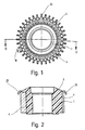
- a plug-in commutator has an electrically insulating material Hub body 1, which is evenly distributed over its circumference arranged, identically formed and extending in the axial direction, and is provided radially open grooves 2. As can be seen in FIG. 2 lets, the grooves 2 begin at one end of the hub body 1, end but at a distance from the other end, this end of all grooves 2 in one Radial plane lies.
- the hub body 1 consists of a Phenolic-based molding compound. But there are also other insulating materials, such as thermoplastics or ceramics. Furthermore, that Material have a fiber reinforcement.
- the hub body 1 can according to the Manufacturing at a temperature that is above the operating temperature be annealed.
- a segment 4 is arranged in each of the grooves 2.
- the same trained Segments 4 consist of an electrical common for commutator segments well conductive material.
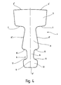
- the segments 4 a head part 5, the cylindrically curved end face 5 'of a part of the Brush tread forms.
- the segments 4 are symmetrical to their longitudinal center plane 6 trained.
- the head part 5 closes with formation a shoulder 7 to a middle part 8, the one measured in the circumferential direction Width at the end that merges into the shoulders 7 by the width of the shoulders 7 is less than the width of the head part 5.
- Die Shoulders close an obtuse angle opening towards the end face 5 ' on.
- the foot part 9 Widened from the head part 5 to a foot part designated as a whole as 9 the middle part 8 is wedge-like. Close its two flat flanks 8 ' in the embodiment an angle of 20 °.
- the foot part 9 has one the first section adjoining the middle part 8 via a shoulder 10 each 11, whose width in the area of the shoulders 10 by their width is smaller than that of the middle part 8.
- the width of the first section 11 takes evenly against the adjoining second section 12 from.
- a shoulder 13 closes with a correspondingly greater width the second section 12, the width of which is uniform towards its end face 9 ' decreases.
- the foot part 9 therefore has a T-like cross-sectional profile.
- each groove 2 has a cross-sectional shape that is geometrically similar to the foot part 9, however, the dimensions of the grooves 2 are slightly larger in this part than the dimensions of the foot part 9. This is between the foot part 9 and the lateral boundary surfaces of the part 9 receiving the foot part Grooves 2 have a slight gap 17.
- the webs 14 have in the zone 18 in which the when inserting the segments 4 in the grooves 2 leading end portion of the Segments 4 comes to rest in the fully inserted state
- End faces 15 of the webs 14 in the radial direction an oversize, which like that 5 shows a section through zone 18, which leads to that the shoulders 7 rest against the end surfaces 15 with pressure, whereby the clamping force is increased, which of the webs 14 on the flanks 8 'of the middle part 8 is exercised.
- the latter clamping force has one Component, which is directed against the foot part 9.
- the gap 17 extends located in the zone 18 between the end surface 9 'of the foot part 9 and the bottom the groove 2.
- the axial length of the zone 18 having the oversize x is about 15% of the axial length of the grooves 2 in the exemplary embodiment
- Ramp 19 is the transition from zone 18 to the rest of the area Bars 14 in which the end faces 15 of the bars 14 have a negative oversize, that is have an undersize y. Where there is undersize y is, as well Fig. 6 shows a gap 20 between the end faces 15 of the webs 14 and Shoulders 7 present.
- the segments 4 In the area of the lagging when the segments 4 are inserted into the grooves 2
- the end section the segments 4 have a zone 21 with an oversize z in radial direction of the end face 9 'of its foot part 9.
- This oversize z has how 6 shows a section through zone 21, for Consequence that the end surface 9 'with pressure at the bottom of the assigned groove 2nd is present and increases the clamping force which the webs 14 on the flanks 8 'of Exercise middle section 8.
- zone 21 between the Shoulders 7 and the end faces 15 of the webs 14 correspond to the gap 20 narrow slot 22 available.
- the oversize x and z are chosen so that in zones 18 and 21 the segments 4 exerted clamping forces for safe positioning and fixing the segments 4 in the hub body 1 does not fall below the necessary value.
- hook 25 which are integrally formed on the segments 4 and Connection of the segments 4 serve with conductors of a rotor winding.
- each segment 104 has two pairs of contact surfaces, and the rest in all details not described with the first embodiment matches.
- the middle part 108 of each segment 104 has, as in first exemplary embodiment, a pair of flanks 108 ', which serve as contact surfaces are formed on the webs 114 of the hub body 101. That radially after Flank 108 'opened on the inside encloses an angle ⁇ .
- the radially inside located foot part 109 of each segment 104 has a further pair of flanks 113, which are also designed as contact surfaces on the webs 114 are.
- the further flank pair 113 encloses an angle ⁇ and is also opened radially inwards.
- the hooks 25 according to Production of segments 4, 104 still bent in the tool.
- the segments 4, 104 are then pushed directly into the hub body 1, 101, that is under Pressure inserted.
- the parameters for pushing in, in particular pressure and optionally temperature, are chosen so that no indissoluble Press connection is created.
- you can still insert the segments 4, 104 the bore of the hub body 1,101 are machined.
Description
Die Erfindung betrifft einen Steckkommutator, der die Merkmale des Oberbegriffs
des Anspruches 1 aufweist, und ein Verfahren zu dessen Herstellung, das
die Merkmale des Oberbegriffs des Anspruches 15 aufweist.The invention relates to a plug-in commutator, which has the features of the preamble
of claim 1, and a method for its production, the
has the features of the preamble of
Bei einem bekannten Steckkommutator dieser Art (WO 95/14319) ist die zum Einstecken der Segmente in die Nuten aufzubringende Kraft so groß, daß Störungen beim Einstecken nicht ausgeschlossen werden können. Würde man diese Kraft dadurch reduzieren, daß man das Übermaß der Segmente und/oder das Untermaß der Nuten verkleinert, wäre eine zuverlässige Positionierung der Segmente im Nabenkörper nicht mehr gewährleistet.In a known plug-in commutator of this type (WO 95/14319) is the Inserting the segments into the force to be applied is so great that Malfunctions during insertion cannot be ruled out. You would reduce this force by adjusting the excess of the segments and / or reducing the undersize of the grooves would be a reliable positioning of the Segments in the hub body are no longer guaranteed.
Der Erfindung liegt deshalb die Aufgabe zugrunde, einen Steckkommutator zu
schaffen, bei dem trotz einer verringerten Kraft für das Einstecken der Segmente
in die Nuten die Segmente zuverlässig in den Nuten positioniert sind. Diese
Aufgabe löst ein Steckkommutator mit den Merkmalen des Anspruches 1,
wobei unter einem Übermaß auch ein eine Klemmkraft bewirkendes Untermaß
zu verstehen ist. Ein Verfahren zur Herstellung des erfindungsgemäßen Steckkommutators
ist Gegenstand des Anspruch 15. Vorteilhafte Ausgestaltungen des
erfindungsgemäßen Steckkommutators und des erfindungsgemäßen Herstellungsverfahrens
sind Gegenstand der Unteransprüche. The invention is therefore based on the object of a plug-in commutator
create, despite a reduced force for inserting the segments
the segments are reliably positioned in the grooves in the grooves. This
The task is solved by a plug-in commutator with the features of claim 1,
an undersize causing a clamping force
is to be understood. A method for producing the plug-in commutator according to the invention
is the subject of
Für eine exakte und zuverlässige Positionierung der Segmente in den Nuten ist es, wie sich gezeigt hat, völlig ausreichend, wenn der maximale Wert der auf die Segmente ausgeübten Klemmkraft durch die Klemmung im Bereich der beiden Endabschnitte der Segmente bestimmt wird. Außerdem wird dadurch, daß hohe Klemmkräfte und damit hohe, beim Einstecken der Segmente in die Nuten zu überwindende Reibungskräfte nur in den beiden Endabschnitten auftreten, die für das gleichzeitig bei allen Segmenten erfolgende Einstecken in die Nuten aufzubringende Kraft erheblich reduziert, wobei der Maximalwert dieser Kraft nur auftritt, während das nacheilende Ende der Segmente in die Nuten eintritt.For an exact and reliable positioning of the segments in the grooves it, as has been shown, is entirely sufficient if the maximum value of the on the segments exerted clamping force by clamping in the area of two end sections of the segments is determined. In addition, that high clamping forces and thus high when inserting the segments in the Grooves friction forces to be overcome only in the two end sections occur for the simultaneous insertion in all segments in the force to be applied significantly reduced, the maximum value this force only occurs during the trailing end of the segments in the Grooves occurs.
Bei einer bevorzugten Ausführungsform haben die Nuten in demjenigen Endabschnitt, der das beim Einstecken voreilende Ende der Segmente aufnimmt, und die Segmente in ihrem nacheilenden Endabschnitt das erforderliche Übermaß. Die Segmente können dann so weit mit sehr geringer Kraft in die Nuten eingesteckt werden, bis das voreilende Ende den das Übermaß aufweisenden Endabschnitt der Nuten erreicht und der nacheilende Endabschnitt der Segmente in die Nuten eintritt.In a preferred embodiment, the grooves in that end section have which takes up the leading end of the segments when inserted, and the segments in their trailing end section the required excess. The segments can then go into the grooves with very little force be inserted until the leading end has the excess End portion of the grooves reached and the trailing end portion of the segments enters the grooves.
Die axiale Erstreckung der das Übermaß aufweisenden Zonen kann unterschiedlich sein. Dabei kommt sowohl eine größere axiale Erstreckung im Bereich des beim Einstecken voreilenden Endabschnittes der Segmente in Frage als auch im Bereich von deren nacheilendem Ende. Bei einer Ausführungsform liegt die axiale Erstreckung der das Übermaß aufweisenden Zonen im Bereich des voreilenden Endabschnittes bei etwa 15% und im Bereich des nacheilenden Endabschnittes bei etwa 5% der Länge des die Bürstenlaufbahn bildenden Teiles der Segmente.The axial extent of the zones having the excess can vary his. Both a larger axial extension in the Area of the leading end section of the segments when inserted as well as in the area of their lagging end. In one embodiment the axial extent of the zones having the excess lies in the range of the leading end section at about 15% and in the area of the trailing End section at about 5% of the length of the brush track Part of the segments.
In dem zwischen den beiden Endabschnitten liegenden Mittelabschnitt der Segmente und Nuten kann zwischen den sich in radialer Richtung überdeckenden Flächenbereichen der Segmente und des Nabenkörpers ein Zwischenraum vorhanden sein, der allerdings in der Regel relativ gering sein wird.In the middle section between the two end sections Segments and grooves can be between those overlapping in the radial direction Surface areas of the segments and the hub body an intermediate space be present, which, however, will usually be relatively small.
Bei einer bevorzugten Ausführungsform weisen die Segmente zwischen ihrem die Bürstenlauffläche bildenden Kopfteil und einem Fußteil einen sich vom Kopfteil zum Fußteil keilartig verbreiternden Mittelteil auf, der zwischen den Flanken der zugeordneten Nut eingeklemmt ist. Dank der Keilform dieses Mittelteils hat die auf die Flanken des Mittelteils wirkende Klemmkraft eine radiale Komponente, welche die für die radiale Positionierung vorgesehenen Flächen der Segmente gegen die ihnen zugeordneten Flächen des Nabenkörpers preßt.In a preferred embodiment, the segments have between them the brush tread forming a head part and a foot part from the Head part to the foot part widening middle part, which between the Flanks of the assigned groove is clamped. Thanks to the wedge shape of this The central part has a clamping force acting on the flanks of the central part radial component, which is intended for radial positioning Surfaces of the segments against the surfaces of the hub body assigned to them presses.
Wenn, wie dies bei einer bevorzugten Ausführungsform der Fall ist, die in der Umfangsrichtung des Kommutators gemessene Breite des Kopfteils der Segmente größer ist als die entsprechende Breite des Mittelteils an dem sich an den Kopfteil anschließenden Ende und die Segmente am Übergang vom Mittelteil zum Kopfteil auf beiden Seiten je eine Schulter aufweisen, welche die unmittelbar benachbarten, die Nuten seitlich begrenzenden Stege des Nabenkörpers übergreifen, kann die radiale Positionierung der Segmente dadurch erfolgen, daß diese Schultern gegen die ihnen zugekehrten Flächenbereiche der Stege gedrückt werden.If, as is the case with a preferred embodiment, that in the Circumferential direction of the commutator measured width of the head part of the segments is greater than the corresponding width of the central part on which the Head part adjoining end and the segments at the transition from the middle part have a shoulder on both sides of the headboard, which is the most immediate adjacent, laterally delimiting webs of the hub body overlap, the radial positioning of the segments can be done by that these shoulders against the surface areas of the webs facing them be pressed.
Vorzugsweise übergreifen die beiden Schultern dieses Segmentes weniger als die Hälfte der ihnen zugewandten Endfläche der unmittelbar benachbarten Stege. Zwischen den Kopfteilen zweier benachbarter Segmente ist dann der in Umfangsrichtung erforderliche Abstand vorhanden. Dabei ist der Zwischenraum zwischen den Kopfteilen benachbarter Segmente vorzugsweise frei von Materialpartien des Nabenkörpers. The two shoulders of this segment preferably overlap less than half of the end face of the immediately adjacent one facing them Walkways. Between the head parts of two adjacent segments is the in The required circumferential distance exists. There is the space between the head parts of adjacent segments, preferably free of material parts of the hub body.
Bei einer bevorzugten Ausführungsform weist der Fußteil jedes Segmentes im Anschluß an das breitere Ende des Mittelteils in einem ersten Abschnitt eine reduzierte Breite unter Bildung je einer Stufe im Bereich beider Flanken und in einem sich an den ersten Abschnitt anschließenden zweiten Abschnitt eine gegenüber dem ersten Abschnitt größere Breite unter Bildung je einer Stufe im Bereich beider Flanken auf. Der Fußteil hat hierbei also ein T-ähnliches Querschnittsprofil.In a preferred embodiment, the foot portion of each segment has Connection to the wider end of the middle part in a first section reduced width with formation of a step in the area of both flanks and in a second section adjoining the first section Compared to the first section greater width, forming one step each Area on both flanks. The foot section has a T-like cross-sectional profile.
Vorzugsweise liegt der Mittelteil der Segmente vollflächig an den Flanken der aufnehmenden Nut an. Statt einer Anlage der am Übergang vom Mittelteil zum Kopfteil vorhandenen Schultern der Segmente an den Endflächen der Stege kann man auch eine Anlage der dem Kopfteil abgewandten Endfläche des Fußteils unter Druck am Grund der das Segment aufnehmenden Nut zum Zwecke der radialen Positionierung vorsehen. Besonders vorteilhaft ist es, die letztgenannte Anlage im Bereich des nacheilenden Endes der Segmente und die Anlage der Schultern an den Endflächen der Stege im Bereich des voreilenden Endes vorzusehen.Preferably, the middle part of the segments lies over the entire surface on the flanks of the receiving groove. Instead of a system at the transition from the middle section to the Headboard existing shoulders of the segments on the end faces of the webs you can also plant the end surface of the end facing away from the Foot part under pressure at the bottom of the groove receiving the segment Provide for radial positioning purposes. It is particularly advantageous the latter plant in the area of the trailing end of the segments and the The shoulders rest on the end faces of the webs in the area of the leading To be provided in the end.
Für die Anwendung der erfindungsgemäßen Lehre ist es unerheblich, welche Größe der Kommutator aufweist oder wie das Verhältnis von Teilung und Größe des Kommutators ist. Bei Steckkommutatoren mit einem kleinen Durchmesser und einer hohen Teilung kann es jedoch sein, daß bei Einhaltung des notwendigen Abstandes zwischen den einzelnen Segmenten die als Anlageflächen dienenden Flanken der Segmente zu kurz ausgebildet sind. Für die Erfüllung der Leistungsanforderungen ist es daher von Vorteil, wenn die Segmente zur Verankerung wenigstens zwei Paare von Anlageflächen aufweisen. Vorzugsweise sind die Winkel zwischen den Paaren für jedes Paar unterschiedlich. Dadurch ist sichergestellt, daß alle Anlageflächen trotz Fertigungstoleranzen an den Stegen anliegen. For the application of the teaching according to the invention it is irrelevant which one Size of the commutator or how the ratio of division and Commutator size is. For plug-in commutators with a small diameter and a high division, it may be that if the necessary distance between the individual segments as the contact surfaces serving flanks of the segments are too short. For fulfillment the performance requirements, it is therefore advantageous if the segments have at least two pairs of contact surfaces for anchoring. Preferably the angles between the pairs are different for each pair. This ensures that all contact surfaces despite manufacturing tolerances rest against the webs.
Bei der Herstellung von üblichen Kommutatoren werden die Segmente zunächst in einen Korb eingesetzt, der beim Einstecken der Segmente in die Nuten die Positionierung vorgibt. Dieser Korb wird dann nach dem Einstecken der Segmente in ein Spritz- oder Preßwerkzeug eingebracht und mitverpreßt bzw. mitverspritzt. Der Kunststoffkorb ist nur einmal verwendbar. Demgegenüber wird bei dem erfindungsgemäßen Verfahren, bei dem die Klemmkraft allein durch das Übermaß im Bereich der Endabschnitte der Segmente und/oder der der Anlage der Segmente dienenden Materialpartie des Nabenkörpers bestimmt wird, auf den Korb verzichtet. Die exakte Positionierung erfolgt durch die Bereiche, die nicht mit Übermaß versehen sind. Die Klemmkraft, die sich am Ende des Einsteckvorgangs aufbaut, beeinflußt diese Positionierung nicht mehr. Mit dem Wegfall des Korbes ist sowohl eine Materialersparnis als auch eine Verkürzung des Herstellungsverfahrens um die Schritte des Bestückens und des Entfernen des Korbes verbunden. Durch den Wegfall des Korbes ist es auch möglich, daß die dem elektrischen Anschluß der Segmente dienenden Haken bereits bei der Herstellung der Segmente im Werkzeug gebogen werden. Der Arbeitsgang Biegen entfällt.When manufacturing common commutators, the segments are first placed in a basket which is inserted into the Grooves dictates the positioning. This basket will then be plugged in the segments are inserted into an injection or pressing tool and pressed together or sprayed with. The plastic basket can only be used once. In contrast is in the method according to the invention, in which the clamping force solely by the excess in the area of the end sections of the segments and / or the part of the material of the hub body which serves to place the segments is determined, waived the basket. The exact positioning is done by the areas that are not oversized. The clamping force itself builds up at the end of the insertion process, does not affect this positioning more. With the elimination of the basket there is both a material saving as well a shortening of the manufacturing process by the assembly steps and removing the basket. By dropping the basket it is it is also possible that those serving for the electrical connection of the segments Hooks are bent in the tool during the manufacture of the segments. The bending step is eliminated.
Vorteilhafterweise sind der Druck und gegebenenfalls die Temperatur beim Einstecken der Segmente so gewählt, daß nicht eine weitgehend unauflösliche Preßverbindung zwischen Nabenkörper und Segmenten entsteht, sondern daß der Nabenkörper und die Segmente wieder voneinander getrennt werden können. Ein nach einem solchen Verfahren hergestellter Steckkommutator ist damit recyclebar.The pressure and, if appropriate, the temperature are advantageously at Inserting the segments chosen so that not a largely indissoluble Press connection between the hub body and segments arises, but that the hub body and the segments are separated again can. A plug-in commutator produced by such a method is therefore recyclable.
Im folgenden ist die Erfindung anhand zweier in der Zeichnung dargestellter Ausführungsbeispiele im einzelnen erläutert. Es zeigen
- Fig. 1
- eine Stirnansicht des ersten Ausführungsbeispiels,
- Fig. 2
- einen Schnitt nach der Linie II - II der Fig. 1,
- Fig. 3
- einen vergrößert dargestellten Ausschnitt aus Fig. 2,
- Fig. 4
- eine Stirnansicht eines der Segmente,
- Fig. 5
- einen vergrößert und unvollständig dargestellten Querschnitt des ersten Ausführungsbeispiels im Bereich des voreilenden Endabschnittes der Segmente,
- Fig. 6
- einen Querschnitt entsprechend Fig. 5 des ersten Ausführungsbeispiels im Bereich des nacheilenden Endabschnittes der Segmente,
- Fig. 7
- einen vergrößert und unvollständig dargestellten Querschnitt des zweiten Ausführungsbeispiels im Bereich des nacheilenden Endabschnitts der Segmente.
- Fig. 1
- 2 shows an end view of the first exemplary embodiment,
- Fig. 2
- 2 shows a section along the line II-II of FIG. 1,
- Fig. 3
- 2 shows an enlarged section from FIG. 2,
- Fig. 4
- an end view of one of the segments,
- Fig. 5
- 3 shows an enlarged and incompletely illustrated cross section of the first exemplary embodiment in the region of the leading end section of the segments,
- Fig. 6
- 5 shows a cross section corresponding to FIG. 5 of the first exemplary embodiment in the region of the trailing end section of the segments,
- Fig. 7
- an enlarged and incompletely shown cross section of the second embodiment in the region of the trailing end portion of the segments.
Ein Steckkommutator weist einen aus elektrisch isolierendem Material bestehenden Nabenkörper 1 auf, der mit gleichmäßig über seinen Umfang verteilt angeordneten, gleich ausgebildeten und in axialer Richtung verlaufenden, sowie radial nach außen offenen Nuten 2 versehen ist. Wie Fig. 2 erkennen läßt, beginnen zwar die Nuten 2 am einen Ende des Nabenkörpers 1, enden aber im Abstand vom anderen Ende, wobei dieses Ende aller Nuten 2 in einer Radialebene liegt. Der Nabenkörper 1 besteht im Ausführungsbeispiel aus einer Formmasse auf Phenolbasis. Es kommen aber auch andere Isoliermaterialien, wie beispielsweise Thermoplaste oder Keramik, in Frage. Ferner kann das Material eine Faserverstärkung aufweisen. Der Nabenkörper 1 kann nach der Herstellung bei einer Temperatur, welche über der Betriebstemperatur liegt, getempert werden. A plug-in commutator has an electrically insulating material Hub body 1, which is evenly distributed over its circumference arranged, identically formed and extending in the axial direction, and is provided radially open grooves 2. As can be seen in FIG. 2 lets, the grooves 2 begin at one end of the hub body 1, end but at a distance from the other end, this end of all grooves 2 in one Radial plane lies. In the exemplary embodiment, the hub body 1 consists of a Phenolic-based molding compound. But there are also other insulating materials, such as thermoplastics or ceramics. Furthermore, that Material have a fiber reinforcement. The hub body 1 can according to the Manufacturing at a temperature that is above the operating temperature be annealed.
In jeder der Nuten 2 ist ein Segment 4 angeordnet. Die gleich ausgebildeten
Segmente 4 bestehen aus einem für Kommutatorsegmente üblichen, elektrisch
gut leitenden Material. Wie beispielsweise Fig. 4 zeigt, weisen die Segmente 4
einen Kopfteil 5 auf, dessen zylindrisch gekrümmte Endfläche 5' einen Teil der
Bürstenlauffläche bildet. Die Segmente 4 sind symmetrisch zu ihrer Längsmittelebene
6 ausgebildet. An den Kopfteil 5 schließt sich unter Bildung je
einer Schulter 7 ein Mittelteil 8 an, dessen in Umfangsrichtung gemessene
Breite an dem über je eine Ausrundung in die Schultern 7 übergehenden Ende
um die Breite der Schultern 7 geringer ist als die Breite des Kopfteils 5. Die
Schultern schließen einen sich zur Endfläche 5' öffnenden, stumpfen Winkel
ein. Vom Kopfteil 5 zu einem als Ganzes mit 9 bezeichneten Fußteil hin verbreitert
sich der Mittelteil 8 keilartig. Seine beiden ebenen Flanken 8' schließen
im Ausführungsbeispiel einen Winkel von 20° ein. Der Fußteil 9 weist einen
sich an den Mittelteil 8 über je eine Schulter 10 anschließenden ersten Abschnitt
11 auf, dessen Breite im Bereich der Schultern 10 um deren Breite
geringer ist als diejenige des Mittelteils 8. Die Breite des ersten Abschnittes 11
nimmt gegen den sich an ihn anschließenden zweiten Abschnitt 12 gleichmäßig
ab. Über je eine Schulter 13 schließt sich mit entsprechend größerer Breite
der zweite Abschnitt 12 an, dessen Breite gegen seine Endfläche 9' hin gleichmäßig
abnimmt. Der Fußteil 9 hat deshalb ein T-ähnliches Querschnittsprofil.A
Wie insbesondere Fig. 5 zeigt, übergreifen, wenn die Segmente 4 in die Nuten
2 eingesteckt sind, die beiden Schultern 7 die die Nut seitlich begrenzenden
Stege 14 des Nabenkörpers 1, und zwar um weniger als die Hälfte der dem
Kopfteil 5 zugekehrten Endfläche 15. Daher ist zwischen zwei benachbarten
Segmenten 4 ein Schlitz 16 vorhanden, in den im Ausführungsbeispiel keine
Materialpartie des Nabenkörpers 1 hineinragt. Die die Schlitze 16 begrenzenden
Seitenflächen der Kopfteile 5 verlaufen parallel zueinander. As particularly shown in Fig. 5, overlap when the
Wie Fig. 5 weiterhin zeigt, liegen die beiden Flanken 8' des Mittelteils 8 jedes
Segmentes 4 vollflächig an den Stegen 14 an. Der den Fußteil 9 aufnehmende
Teil jeder Nut 2 hat eine dem Fußteil 9 geometrisch ähnliche Querschnittsform,
jedoch sind die Abmessungen der Nuten 2 in diesem Teil geringfügig größer
als die Abmessungen des Fußteils 9. Dadurch ist zwischen dem Fußteil 9 und
den seitlichen Begrenzungsflächen des den Fußteil 9 aufnehmenden Teils der
Nuten 2 ein geringfügiger Spalt 17 vorhanden.5 further shows, the two flanks 8 'of the
Wie Fig. 3 zeigt, haben die Stege 14 in derjenigen Zone 18, in welcher der
beim Einstecken der Segmente 4 in die Nuten 2 voreilende Endabschnitt der
Segmente 4 im vollständig eingesteckten Zustand zu liegen kommt, an den
Endflächen 15 der Stege 14 in radialer Richtung ein Übermaß, welches wie die
einen Schnitt durch die Zone 18 darstellende Fig. 5 erkennen läßt, dazu führt,
daß die Schultern 7 vollflächig mit Druck an den Endflächen 15 anliegen,
wodurch die Klemmkraft erhöht wird, welche von den Stegen 14 auf die Flanken
8' des Mittelteils 8 ausgeübt wird. Die letztgenannte Klemmkraft hat eine
Komponente, welche gegen den Fußteil 9 gerichtet ist. Der Spalt 17 erstreckt
sich in der Zone 18 zwischen die Endfläche 9' des Fußteils 9 und den Grund
der Nut 2. Die axiale Länge der das Übermaß x aufweisenden Zone 18 beträgt
im Ausführungsbeispiel etwa 15% der axialen Länge der Nuten 2. Über eine
Rampe 19 erfolgt der Übergang von der Zone 18 zu dem übrigen Teil der
Stege 14, in denen die Endflächen 15 der Stege 14 ein negatives Übermaß, also
ein Untermaß y haben. Dort, wo das Untermaß y vorhanden ist, ist, wie auch
Fig. 6 zeigt, ein Spalt 20 zwischen den Endflächen 15 der Stege 14 und den
Schultern 7 vorhanden.As FIG. 3 shows, the
Im Bereich des beim Einstecken der Segmente 4 in die Nuten 2 nacheilenden
Endabschnittes haben die Segmente 4 eine Zone 21 mit einem Übermaß z in
radialer Richtung der Endfläche 9' ihres Fußteiles 9. Dieses Übermaß z hat, wie
die einen Schnitt durch die Zone 21 darstellende Fig. 6 erkennen läßt, zur
Folge, daß die Endfläche 9' mit Druck am Grund der zugeordneten Nut 2
anliegt und die Klemmkraft erhöht, welche die Stege 14 auf die Flanken 8' des
Mittelteils 8 ausüben. Infolgedessen ist im Bereich der Zone 21 zwischen den
Schultern 7 und den Endflächen 15 der Stege 14 ein dem Spalt 20 entsprechend
schmaler Schlitz 22 vorhanden.In the area of the lagging when the
Die Übermaße x und z sind so gewählt, daß die in den Zonen 18 und 21 auf
die Segmente 4 ausgeübten Klemmkräfte den für eine sichere Positionierung
und Festlegung der Segmente 4 im Nabenkörper 1 notwendigen Wert nicht unterschreitet.The oversize x and z are chosen so that in
Dennoch ist die erforderliche Kraft für das gleichzeitige Einstecken aller Segmente
4 in die Nuten 2 vom Beginn des Einsteckvorganges bis zum Erreichen
der Zone 18 durch das voreilende Ende der Segmente 4 sehr gering, weil
hierbei nur die zunächst allenfalls geringen Klemmkräfte, welche die Stege 14
auf den Mittelteil 8 der Segmente ausüben, überwunden werden müssen. Erst
beim Eindringen des voreilenden Endabschnittes der Segmente 4 in die Zone
18 steigt die erforderliche Einschubkraft stark an und erreicht ihren Maximalwert,
wenn die Endfläche 9' des Fußteils 9 in der Zone 21 in Anlage an den
Grund der zugeordneten Nut 2 kommt, wobei dieser Einlauf durch eine Rampe
als Übergang zur Zone 21 erleichtert wird. Wenn die Segmente 4 vollständig in
die Nuten 2 eingesteckt sind, liegt, wie Fig. 3 zeigt, das voreilende Ende an
einer Fläche 23 an, welche im Abstand von der im benachbarten, im Ausführungsbeispiel
konischen Stirnfläche 24 des Nabenkörpers 1 liegt und die Nut 2
in axialer Richtung begrenzt. Alle Flächen 23 liegen in einer gemeinsamen
Radialebene.Nevertheless, the force required to insert all segments at the
An der Außenmantelfläche des von den Flächen 23 und der konischen Stirnfläche
24 begrenzten Endabschnittes des Nabenkörpers 1 liegen im Ausführungsbeispiel
Haken 25 an, die an die Segmente 4 angeformt sind und der
Verbindung der Segmente 4 mit Leitern einer Rotorwicklung dienen.On the outer surface of the
Ein weiteres Ausführungsbeispiel betrifft einen Steckkommutator, dessen Segmente
104 zwei Paare von Anlageflächen aufweisen, und der im übrigen in
allen nicht beschriebenen Einzelheiten mit dem ersten Ausführungsbeispiel
übereinstimmt. Das Mittelteil 108 eines jeden Segmentes 104 weist, wie im
ersten Ausführungsbeispiel, ein Paar Flanken 108' auf, welche als Anlageflächen
an die Stege 114 des Nabenkörpers 101 ausgebildet sind. Das radial nach
innen geöffnete Flankenpaar 108' schließt einen Winkel α ein. Der radial innen
gelegene Fußteil 109 eines jeden Segmentes 104 weist ein weiteres Paar Flanken
113 auf, welche ebenfalls als Anlageflächen an die Stege 114 ausgebildet
sind. Das weitere Flankenpaar 113 schließt einen Winkel β ein und ist ebenfalls
radial nach innen geöffnet. Der Winkel β ist kleiner als der Winkel α. Im
Grenzfall kann β = 0° sein, d.h. die Flanken 113 verlaufen parallel zueinander.Another embodiment relates to a plug-in commutator, the
Beim Einstecken der Segmente 104 in die Nuten 102 des Nabenkörpers 101
werden die Segmente 104 durch das Übermaß im Endabschnitt radial nach
außen gedrückt. Dabei kommen zunächst die am Fußteil 109 vorgesehenen
Flanken 113 in Anlage mit den Stegen 114. Durch den kleinen Winkel β
wirken die Stege 114 dem Einstecken der Segmente 104 nur mit geringer Kraft
entgegen. Beim weiteren Einstecken werden die Flanken 113 so weit in den
Nabenkörper 101 eingedrückt, bis die am Mittelteil 108 vorgesehenen Flanken
108' in Anlage mit den Stegen 114 kommen. Bei richtiger Wahl der Winkel α
und β und der sonstigen Dimensionierungen der Segmente 104 und der Stege
114 kommen so alle Flankenpaare 108' und 113 in Anlage an die Stege 114.
Bei druckfesten Nabenkörpern 101 ist es von Vorteil, wenn die Stege 114 im
Bereich der Fußteile 109 zueinander einen gegenüber β etwas größeren Öffnungswinkel
nach innen aufweisen. Dadurch kommt nur ein Teil der Flanken
113 in Anlage, was die entgegenwirkende Kraft verringert.When the
Bei einem erfindungsgemäßen Verfahren werden die Haken 25 nach der
Herstellung der Segmente 4, 104 noch im Werkzeug gebogen. Die Segmente 4,
104 werden dann direkt in den Nabenkörper 1, 101 eingestoßen, also unter
Druck eingesteckt. Die Parameter für das Einstoßen, insbesondere Druck und
gegebenenfalls Temperatur, werden dabei so gewählt, daß keine unauflösliche
Preßverbindung entsteht. Wahlweise kann noch nach dem Einstoßen der Segmente
4, 104 die Bohrung des Nabenkörpers 1,101 bearbeitet werden.In a method according to the invention, the
Claims (17)
- Plug-in commutator having a hub body (1; 101) which comprises electrically insulating material and which has identical grooves (2; 102) distributed uniformly over its circumference into each of which one of a number of identical segments (4; 104) forming the brush contact face is inserted, so forming a connection interlocking in the radial direction, and is secured against displacement relative to the hub body (1; 101) by a clamping force which is based on an overdimensioned portion (x) of the segments (4; 104) and/or of the material portions of the hub body (1; 101) that are used for the abutment of the segments (4; 104), characterised in that the overdimensioned portion (x) is provided only in the region of the two end portions of the segments (4; 104) and/or of the grooves (2; 102).
- Commutator according to claim 1, characterised in that the hub body (1; 101) has an oversized portion in that region (18) which receives the end portion of the segments (4; 104) that is at the front during insertion, and the segments (4; 104) have an overdimensioned portion in the end portion that is at the back during insertion.
- Commutator according to claim 2, characterised in that the axial extent of the region (18) of the hub body (1; 101) that has the overdimensioned portion is larger than the corresponding extent of the region (21) of the segments (4; 104) that has the overdimensioned portion.
- Commutator according to any one of claims 1 to 3, characterised in that, in the middle portion of both the segments (4; 104) and the grooves (2; 102), which middle portion lies between the two end portions, a space (17, 20, 22) is present between the mutually radially overlapping face regions of the segments (4; 104) and of the hub body (1; 101).
- Commutator according to any one of claims 1 to 4, characterised in that the segments (4; 104) have, between their head portion (5) forming the brush contact face and a foot portion (9; 109), a middle portion (8; 108) which widens in the manner of a wedge from the head portion (5) to the foot portion (9; 109) and which is clamped between the flanks of the associated groove (2; 102).
- Commutator according to claim 5, characterised in that the width of the head portion (5) of the segments (4; 104), measured in the circumferential direction of the head portion (5), is larger than the corresponding width of the middle portion (8; 108) at the end adjoining the head portion (5), and in that the segments (4; 104) have, at the transition from the middle portion (8; 108) to the head portion (5), on both sides, in each case one shoulder (7), the shoulders engaging over the immediately adjacent teeth (14; 114) of the hub body (1; 101) which delimit the groove (2; 102) laterally.
- Commutator according to claim 6, characterised in that the two shoulders (7) of each segment (4; 104) engage over less than half of the end face (15) of the immediately adjacent teeth (14; 114) which faces them.
- Commutator according to claim 7, characterised in that the space between the head portions (5) of adjacent segments (4; 104) is free from material portions of the hub body (1; 101).
- Commutator according to any one of claims 5 to 8, characterised in that the foot portion (9) of each segment (4) has, adjoining the wider end of the middle portion (8), a reduced width in a first portion (11), so forming in each case one shoulder (13) in the region of the two flanks, and, in a second portion (12) adjoining the first portion (11), a width larger than the first width, so forming in each case one shoulder (13) in the region of the two flanks.
- Commutator according to any one of claims 5 to 9, characterised in that the middle portion (8; 108) of the segments (4; 104) is in full-face abutment with the flanks of the groove (2; 102) receiving it.
- Commutator according to any one of claims 5 to 10, characterised in that the shoulders (7) of the segments (4; 104), which shoulders are formed at the transition from the middle portion (8; 108) to the head portion (5), abut the end faces (15) of the teeth (14; 114) with pressure in that region (18) of the hub body (1; 101) which has the overdimensioned portion.
- Commutator according to any one of claims 5 to 11, characterised in that the end face (9'), remote from the head portion (5), of the foot portion (9) in the region (21) of the segments (4; 104) that has the overdimensioned portion abuts, with pressure, the base of the groove (2; 102) receiving the segment (4; 104).
- Commutator according to any one of claims 1 to 12, characterised by a ramp-like transition from the region without an overdimensioned portion to the region (18, 21) having an overdimensioned portion both in the segments (4; 104) and in the hub body (1; 101).
- Commutator according to any one of claims 1 to 13, characterised by segments (104) having at least two pairs of abutment faces (108', 113), especially with different angles (α, β) between the pairs.
- Method of producing a plug-in commutator according to any one of claims 1 to 14, wherein each of a number of identical segments (4; 104) forming the brush contact face is inserted into one of a number of identical grooves (2; 102) which are provided on a hub body (1; 101) comprising electrically insulating material and which are distributed uniformly over the circumference thereof, so forming a connection interlocking in the radial direction and creating a clamping force which is based on an overdimensioned portion of the segments and/or of that material portion of the hub body (1; 101) which is used for the abutment of the segments (4; 104), which overdimensioned portion is provided only in the region of the two end portions of the segments and/or of the grooves, the segments (4; 104) being positioned only by the grooves (2; 102) and being fixed by the clamping force.
- Method according to claim 15, characterised in that hooks (25), provided at one end of the segments (4; 104) for electrical connection, are bent after insertion.
- Method according to claim 15 or 16, characterised in that the segments (4; 104) are inserted into the grooves (2; 102) of the hub body (1; 101) under such a pressure and at such a temperature that the hub body (1; 101) and the segments (4; 104) can be separated from one another again.
Priority Applications (1)
| Application Number | Priority Date | Filing Date | Title |
|---|---|---|---|
| SI9630208T SI0791236T1 (en) | 1995-08-16 | 1996-08-08 | Plug-in commutator and method for its production |
Applications Claiming Priority (3)
| Application Number | Priority Date | Filing Date | Title |
|---|---|---|---|
| DE19530051A DE19530051C2 (en) | 1995-08-16 | 1995-08-16 | Steckkommutator |
| DE19530051 | 1995-08-16 | ||
| PCT/EP1996/003505 WO1997007573A1 (en) | 1995-08-16 | 1996-08-08 | Plug-in commutator and method for its production |
Publications (2)
| Publication Number | Publication Date |
|---|---|
| EP0791236A1 EP0791236A1 (en) | 1997-08-27 |
| EP0791236B1 true EP0791236B1 (en) | 2000-03-29 |
Family
ID=7769576
Family Applications (1)
| Application Number | Title | Priority Date | Filing Date |
|---|---|---|---|
| EP96928428A Expired - Lifetime EP0791236B1 (en) | 1995-08-16 | 1996-08-08 | Plug-in commutator and method for its production |
Country Status (10)
| Country | Link |
|---|---|
| US (1) | US5760517A (en) |
| EP (1) | EP0791236B1 (en) |
| JP (1) | JPH10507577A (en) |
| BR (1) | BR9606583A (en) |
| DE (2) | DE19530051C2 (en) |
| ES (1) | ES2146409T3 (en) |
| HU (1) | HUP9702438A3 (en) |
| SK (1) | SK47097A3 (en) |
| TR (1) | TR199700298T1 (en) |
| WO (1) | WO1997007573A1 (en) |
Families Citing this family (14)
| Publication number | Priority date | Publication date | Assignee | Title |
|---|---|---|---|---|
| WO1998026478A1 (en) * | 1996-12-12 | 1998-06-18 | Comtrade Handelsgesellshaft Mbh | Commutator with reinforcing ring |
| GB2314693B (en) * | 1997-09-29 | 1998-08-12 | Watliff Co Ltd | A plug in commutator, a plug in segment for making a plug in commutator and a hub body for making a plug in commutator |
| DE19744357A1 (en) * | 1997-10-08 | 1999-04-15 | Bosch Gmbh Robert | Rotary electrical machine commutator |
| US5949174A (en) * | 1998-07-08 | 1999-09-07 | Siemens Canada Limited | Commutator for two speed electric motor and motor incorporating same |
| DE19837961C2 (en) * | 1998-08-21 | 2001-08-16 | Kirkwood Ind Gmbh | Commutator and method of making a commutator |
| DE19922235C2 (en) * | 1998-08-21 | 2002-05-23 | Kirkwood Ind Gmbh | Commutator and method of making a commutator |
| DE19854843A1 (en) * | 1998-11-27 | 2000-06-08 | Kirkwood Ind Gmbh | Device for turning the current, in particular commutator, and method for producing such a device |
| JP3559181B2 (en) * | 1998-11-30 | 2004-08-25 | 三菱電機株式会社 | Motor for electric power steering system |
| JP4166387B2 (en) * | 1999-10-04 | 2008-10-15 | アスモ株式会社 | Electric motor with power supply brush |
| DE10250261A1 (en) * | 2002-10-28 | 2004-06-09 | Kolektor D.O.O. | Commutator for an electrical machine and method for its production |
| DE102005028791A1 (en) * | 2005-06-16 | 2006-12-28 | Kautt & Bux Gmbh | Plan commutator and method for producing a flat commutator |
| JP5340531B2 (en) * | 2006-10-19 | 2013-11-13 | 株式会社デンソー | Rotating electric machine |
| DE102010038993A1 (en) * | 2010-08-06 | 2012-02-09 | BSH Bosch und Siemens Hausgeräte GmbH | Commutator i.e. plug-in commutator, for electric machine for e.g. clothes dryer, has lamella whose cross-sectional profile in holding portion is continuously tapered in section of lamella along radial direction with respect to symmetry axis |
| CN105896225B (en) * | 2016-06-13 | 2018-05-22 | 薛瑞华 | Hooked reverser |
Family Cites Families (6)
| Publication number | Priority date | Publication date | Assignee | Title |
|---|---|---|---|---|
| DE307451C (en) * | ||||
| DE669872C (en) * | 1939-01-05 | Electricitaetsgesellschaft San | Process for the manufacture of collectors | |
| GB1172308A (en) * | 1966-03-22 | 1969-11-26 | Fed Motor Parts Corp Proprieta | Improvements in or relating to Commutators |
| GB2221580B (en) * | 1988-08-04 | 1992-09-23 | Johnson Electric Ind Mfg | A two part commutator assembly for an electric motor |
| WO1995014319A1 (en) * | 1993-11-15 | 1995-05-26 | Kautt & Bux Commutator Gmbh | Commutator and method of manufacturing it |
| SI9300660A (en) * | 1993-12-16 | 1995-06-30 | Kolektor D O O Idrija | Commutator for small and midle electric machines and process for making it |
-
1995
- 1995-08-16 DE DE19530051A patent/DE19530051C2/en not_active Expired - Fee Related
-
1996
- 1996-08-08 WO PCT/EP1996/003505 patent/WO1997007573A1/en active IP Right Grant
- 1996-08-08 US US08/817,396 patent/US5760517A/en not_active Expired - Fee Related
- 1996-08-08 ES ES96928428T patent/ES2146409T3/en not_active Expired - Lifetime
- 1996-08-08 SK SK470-97A patent/SK47097A3/en unknown
- 1996-08-08 TR TR97/00298T patent/TR199700298T1/en unknown
- 1996-08-08 HU HU9702438A patent/HUP9702438A3/en unknown
- 1996-08-08 DE DE59604838T patent/DE59604838D1/en not_active Expired - Fee Related
- 1996-08-08 EP EP96928428A patent/EP0791236B1/en not_active Expired - Lifetime
- 1996-08-08 BR BR9606583A patent/BR9606583A/en not_active Application Discontinuation
- 1996-08-08 JP JP8532824A patent/JPH10507577A/en active Pending
Also Published As
| Publication number | Publication date |
|---|---|
| US5760517A (en) | 1998-06-02 |
| DE19530051A1 (en) | 1997-02-20 |
| TR199700298T1 (en) | 1997-08-21 |
| JPH10507577A (en) | 1998-07-21 |
| BR9606583A (en) | 1997-10-28 |
| DE59604838D1 (en) | 2000-05-04 |
| SK47097A3 (en) | 1997-10-08 |
| EP0791236A1 (en) | 1997-08-27 |
| DE19530051C2 (en) | 2002-02-07 |
| ES2146409T3 (en) | 2000-08-01 |
| WO1997007573A1 (en) | 1997-02-27 |
| HUP9702438A2 (en) | 1998-03-30 |
| HUP9702438A3 (en) | 2000-03-28 |
Similar Documents
| Publication | Publication Date | Title |
|---|---|---|
| DE2538139C2 (en) | screw | |
| EP1207313B1 (en) | Nut and method of manufacturing the same | |
| EP0791236B1 (en) | Plug-in commutator and method for its production | |
| DE3323640A1 (en) | CONNECTING DEVICE BETWEEN A TUBULAR BODY AND A RING-SHAPED PART AND METHOD FOR PRODUCING THIS CONNECTION | |
| EP1046455A2 (en) | Method for removably connecting two members and connection system for realising the method | |
| DE2645034A1 (en) | IGNITION DEVICE, IN PARTICULAR SPARK PLUG OR IGNITION ELECTRODE FOR BURNER | |
| EP1335148B1 (en) | Supporting body, in particular for elastically supporting a sitting or lying furniture | |
| DE3245699C2 (en) | ||
| DE3246626A1 (en) | METHOD AND DEVICE FOR PRODUCING A GUIDE RAIL | |
| EP2179191B1 (en) | Connecting link for an interlocking device and production method | |
| EP0036444B1 (en) | Method of manufacturing commutators by cold-shaping | |
| EP0400345A1 (en) | Fixing element | |
| DE19543998B4 (en) | Method for producing a commutator ring for a commutator | |
| EP0081828A2 (en) | Carbon brush for electrical machines | |
| DE3823845C2 (en) | ||
| WO2010081714A1 (en) | Screw element, screw connection and method for producing a screw element | |
| DE3403268A1 (en) | WIRE CONNECTOR | |
| EP2382397B1 (en) | Multipart screw element, screw connection, and method for producing a multipart screw element | |
| DE2322351A1 (en) | SELF-TAPPING THREADED FASTENING MEMBER AND PROCESS AND PAIR OF THREADED JACKS FOR THE PRODUCTION THEREOF | |
| DE4338588C2 (en) | Oil press connection | |
| DE2500456A1 (en) | ELECTRICAL CONNECTION | |
| DE3637626C2 (en) | Method of fixing a metal pin within a ceramic insulator | |
| DE60310082T2 (en) | PROCESS FOR PERFORMING PREPARATION OF THREADS IN A THREADED COMPONENT, A WINDOW MADE ACCORDING TO THE METHOD AND A SCREW CONNECTION WITH SUCH A LINK | |
| EP0088311B1 (en) | Clamping device for a construction element, especially a screw | |
| DE4039402A1 (en) | SCREW WITH SELF-LOCKING THREAD |
Legal Events
| Date | Code | Title | Description |
|---|---|---|---|
| PUAI | Public reference made under article 153(3) epc to a published international application that has entered the european phase |
Free format text: ORIGINAL CODE: 0009012 |
|
| AK | Designated contracting states |
Kind code of ref document: A1 Designated state(s): DE ES FR GB IT SE |
|
| 17P | Request for examination filed |
Effective date: 19970402 |
|
| RAX | Requested extension states of the european patent have changed |
Free format text: SI PAYMENT 970402 |
|
| RAP1 | Party data changed (applicant data changed or rights of an application transferred) |
Owner name: KIRKWOOD INDUSTRIES GMBH |
|
| GRAG | Despatch of communication of intention to grant |
Free format text: ORIGINAL CODE: EPIDOS AGRA |
|
| 17Q | First examination report despatched |
Effective date: 19990625 |
|
| GRAG | Despatch of communication of intention to grant |
Free format text: ORIGINAL CODE: EPIDOS AGRA |
|
| GRAG | Despatch of communication of intention to grant |
Free format text: ORIGINAL CODE: EPIDOS AGRA |
|
| GRAH | Despatch of communication of intention to grant a patent |
Free format text: ORIGINAL CODE: EPIDOS IGRA |
|
| GRAH | Despatch of communication of intention to grant a patent |
Free format text: ORIGINAL CODE: EPIDOS IGRA |
|
| GRAA | (expected) grant |
Free format text: ORIGINAL CODE: 0009210 |
|
| AK | Designated contracting states |
Kind code of ref document: B1 Designated state(s): DE ES FR GB IT SE |
|
| AX | Request for extension of the european patent |
Free format text: SI PAYMENT 19970402 |
|
| ITF | It: translation for a ep patent filed |
Owner name: BUZZI, NOTARO&ANTONIELLI D'OULX |
|
| ET | Fr: translation filed | ||
| REF | Corresponds to: |
Ref document number: 59604838 Country of ref document: DE Date of ref document: 20000504 |
|
| GBT | Gb: translation of ep patent filed (gb section 77(6)(a)/1977) |
Effective date: 20000629 |
|
| REG | Reference to a national code |
Ref country code: ES Ref legal event code: FG2A Ref document number: 2146409 Country of ref document: ES Kind code of ref document: T3 |
|
| REG | Reference to a national code |
Ref country code: GB Ref legal event code: 711B |
|
| REG | Reference to a national code |
Ref country code: GB Ref legal event code: 711G |
|
| PLBE | No opposition filed within time limit |
Free format text: ORIGINAL CODE: 0009261 |
|
| STAA | Information on the status of an ep patent application or granted ep patent |
Free format text: STATUS: NO OPPOSITION FILED WITHIN TIME LIMIT |
|
| 26N | No opposition filed | ||
| PGFP | Annual fee paid to national office [announced via postgrant information from national office to epo] |
Ref country code: GB Payment date: 20010720 Year of fee payment: 6 Ref country code: FR Payment date: 20010720 Year of fee payment: 6 |
|
| PGFP | Annual fee paid to national office [announced via postgrant information from national office to epo] |
Ref country code: SE Payment date: 20010723 Year of fee payment: 6 |
|
| PGFP | Annual fee paid to national office [announced via postgrant information from national office to epo] |
Ref country code: ES Payment date: 20010810 Year of fee payment: 6 Ref country code: DE Payment date: 20010810 Year of fee payment: 6 |
|
| REG | Reference to a national code |
Ref country code: GB Ref legal event code: IF02 |
|
| PG25 | Lapsed in a contracting state [announced via postgrant information from national office to epo] |
Ref country code: GB Free format text: LAPSE BECAUSE OF NON-PAYMENT OF DUE FEES Effective date: 20020808 |
|
| PG25 | Lapsed in a contracting state [announced via postgrant information from national office to epo] |
Ref country code: SE Free format text: LAPSE BECAUSE OF NON-PAYMENT OF DUE FEES Effective date: 20020809 Ref country code: ES Free format text: LAPSE BECAUSE OF NON-PAYMENT OF DUE FEES Effective date: 20020809 |
|
| PG25 | Lapsed in a contracting state [announced via postgrant information from national office to epo] |
Ref country code: DE Free format text: LAPSE BECAUSE OF NON-PAYMENT OF DUE FEES Effective date: 20030301 |
|
| EUG | Se: european patent has lapsed | ||
| GBPC | Gb: european patent ceased through non-payment of renewal fee |
Effective date: 20020808 |
|
| PG25 | Lapsed in a contracting state [announced via postgrant information from national office to epo] |
Ref country code: FR Free format text: LAPSE BECAUSE OF NON-PAYMENT OF DUE FEES Effective date: 20030430 |
|
| REG | Reference to a national code |
Ref country code: FR Ref legal event code: ST |
|
| REG | Reference to a national code |
Ref country code: ES Ref legal event code: FD2A Effective date: 20030912 |
|
| PG25 | Lapsed in a contracting state [announced via postgrant information from national office to epo] |
Ref country code: IT Free format text: LAPSE BECAUSE OF NON-PAYMENT OF DUE FEES;WARNING: LAPSES OF ITALIAN PATENTS WITH EFFECTIVE DATE BEFORE 2007 MAY HAVE OCCURRED AT ANY TIME BEFORE 2007. THE CORRECT EFFECTIVE DATE MAY BE DIFFERENT FROM THE ONE RECORDED. Effective date: 20050808 |