EP0790489B1 - Vorrichtung und Verfahren zur Umschaltung zwischen verschiedenen Betriebsmodi eines Messwertaufnehmers - Google Patents
Vorrichtung und Verfahren zur Umschaltung zwischen verschiedenen Betriebsmodi eines Messwertaufnehmers Download PDFInfo
- Publication number
- EP0790489B1 EP0790489B1 EP96120019A EP96120019A EP0790489B1 EP 0790489 B1 EP0790489 B1 EP 0790489B1 EP 96120019 A EP96120019 A EP 96120019A EP 96120019 A EP96120019 A EP 96120019A EP 0790489 B1 EP0790489 B1 EP 0790489B1
- Authority
- EP
- European Patent Office
- Prior art keywords
- sensor device
- signal
- mode
- processing unit
- data
- Prior art date
- Legal status (The legal status is an assumption and is not a legal conclusion. Google has not performed a legal analysis and makes no representation as to the accuracy of the status listed.)
- Expired - Lifetime
Links
Images

Classifications
-
- G—PHYSICS
- G01—MEASURING; TESTING
- G01D—MEASURING NOT SPECIALLY ADAPTED FOR A SPECIFIC VARIABLE; ARRANGEMENTS FOR MEASURING TWO OR MORE VARIABLES NOT COVERED IN A SINGLE OTHER SUBCLASS; TARIFF METERING APPARATUS; MEASURING OR TESTING NOT OTHERWISE PROVIDED FOR
- G01D18/00—Testing or calibrating apparatus or arrangements provided for in groups G01D1/00 - G01D15/00
- G01D18/002—Automatic recalibration
- G01D18/006—Intermittent recalibration
Definitions
- the present invention relates to an apparatus and a method for Switching between different operating modes of a sensor according to the preamble of claim 1. Particularly suitable the device according to the invention and the method according to the invention, if a position measuring system is used as a sensor.
- a generic device is for example from GB 2 218 213 A known.
- a sensor in the form of a level meter disclosed between a measurement mode and a calibration mode is switchable.
- a calibrator unit Switchover or calibration signal in the form of a mode word to the sensor transfer.
- the sensor receives the changeover signal receives, it switches to an automatic calibration mode and automatically calibrates itself, i.e. in calibration mode there is none Communication between the sensor and one downstream evaluation device provided.
- the calibration signal is only the automatic self-calibration of the respective transducer, without possibly specifically Adapt the sensor to the conditions on the evaluation side.
- the two signal transmission lines or envisaged transmission protocol between the sensor and the evaluation unit transmits data in the direction of Sensor. Basically, this is not the case with all possible Transmission protocols provided.
- DE 41 29 577 discloses a measuring system for detecting the angle of rotation, in which a modification of measurement system-specific data by the user is possible.
- the measuring system comprises a data memory which is connected to an evaluation unit is connected via signal transmission lines; by temporarily interconnecting the measuring system outputs or memory outputs with the transmission lines, the measuring system can be user-specific be programmed.
- A is used for data transmission time sequential multiplexing proposed what a technically represents a relatively complex solution.
- the synchronization of the measuring system and evaluation unit not guaranteed.
- the proposed one Interface is also not universally applicable for different measuring systems, for example for measuring systems that already have the actual Deliver the measured value in the form of an absolute position and the one of interest Measured value not only in the downstream evaluation unit must be generated.
- a device and a method for synchronous serial data transmission between a sensor and a processing unit is also known from EP 0 171 579.
- the proposed one Device a clock signal and a data line over which the transducer and a downstream processing unit with each other are connected; the two signal transmission lines are only operated unidirectionally.
- User-specific programming of the transducer for example by writing and reading out Storage units that are assigned to the transducer is at this device is not provided or not possible.
- EP 0 660 209 proposes at least one Signal transmission line between the sensor and the processing unit to be carried out bidirectionally and to the sensor allocate a number of memory areas.
- the memory areas can described by the user via this signal transmission line or read out, so that the user can make an adjustment the processing unit to specific transducer parameters is possible.
- the storage areas provided can be very different Parameters of the sensor, information about its operating state, Include parameters of the processing unit etc. With the help of a Such a device is now an optional programming or Measuring operation of the sensor possible.
- This advantageous solution requires certain conditions on the part of the sensor, in particular a bidirectional signal transmission line to the processing unit and is therefore not universally applicable, for example in connection with transducers that can only be operated unidirectionally and have data lines.
- US 4,831,380 discloses an interface for transducers, in which the simultaneous detection of a reference signal Transmission of sensor correction data and measurement data for Processing unit takes place.
- a programming option for the sensor i.e. such as the user-specific adaptation to certain
- the requirements of the processing unit are just as little provided as the defined switching between different Operating modes of the sensor.
- the object of the present invention is therefore a device as well a method for switching between different operating modes
- To create transducers in connection with as many as possible various transducer systems works reliably.
- various measurement modes in which a measurement data transmission to a subordinate processing unit in different
- the programming of the sensor is carried out in the manner be possible by the respective user.
- Such a programming mode e.g. an adaptation of the processing unit to certain Enable parameters of the transducer with little effort.
- a method for solving the problems addressed is characterized by the characterizing features of claim 8. Possible embodiments of the method according to the invention result from the measures listed in the claims dependent on claim 8.
- a comparator unit ensures reliable identification and subsequent Switching to the desired transducer operating mode takes place.
- Various operating modes of the same can be provided here are, for example, different measurement modes in which signals are different Transfer form to a downstream processing unit become.
- it can also be defined in a program lubrication mode can be switched over in which a description and readout of corresponding Memory areas of the transducer can take place etc.
- the device according to the invention and the method according to the invention can be used with conventional interface variants use with unidirectional signal transmission lines, such as in EP 0 171 579.
- devices can or method according to EP 0 660 209 can be optimized with it. The universal use in connection with various measuring sensors is thus ensured.
- the device according to the invention and the method according to the invention can be extremely extreme in this regard be made flexible.
- the device according to the invention as well the inventive method can also be used in conjunction with use a wide variety of transducer designs.
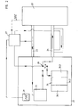
- the device shown comprises on the one hand the transducer (1), which in the exemplary embodiment described below is designed as a position measuring system or as an absolute angle measuring system.
- the sensor (1) is connected to a downstream processing unit (2) via two unidirectionally operated signal transmission lines (3, 4).
- the processing unit (2) therefore corresponds, for example, to a conventional machine tool control.
- the sensor (1) is designed in a known manner to detect the absolute angular position of interest, that is to say analog scanning signals can be generated by photoelectrically scanning a code disk or a plurality of code disks connected to one another by reduction gears.
- the signals are transmitted from the measurement value generation unit (5) via the two signal transmission lines (3, 4) to the downstream processing unit (2) in a measurement mode in a known manner, as described, for example, in EP 0 171 579 .
- the two signal transmission lines (3, 4) are operated unidirectionally, ie a clock (3) and a data line (4) are provided.
- the transmission of defined clock signals from the processing unit (2) via the clock line (3) to the measured value generation unit (5) synchronizes the serial transmission of measured data on the data line (4) in the direction of the processing unit (2).
- the sensor (1) shown further comprises a memory module (6) with several separate memory areas (6.1, 6.2, 6.3).
- the individual memory areas (6.1, 6.2, 6.3) are reserved for various parameter categories and can be defined and read out by the respective user in a programming mode.
- user-specific parameters can be stored in the individual memory areas (6.1, 6.2, 6.3) as well as specific data of the sensor manufacturer, correction data of the sensor (1), operating mode parameters, etc.
- a programming mode can also be implemented or is available to the user stands.
- the operating mode of the sensor (1) for example the indication of the direction of rotation of an angle measuring system, can be predefined, parameters of the sensor manufacturer are read out, etc.
- a comparator unit (7) is provided within the device according to the invention.
- the task of the comparator unit (7) is to continuously detect the signals which are transmitted via at least one of the two signal transmission lines (3, 4) or are present there.
- the detected signals are continuously compared by the comparator unit (7) with predetermined reference signals, so that identification of the respectively activated or desired operating mode is possible in this way.
- the comparator unit (7) therefore recognizes the operating mode desired by the user on the basis of the available reference signals and activates the corresponding switching means (8.1, 8.2) in order to switch between the at least two operating modes.
- the user selects the desired operating mode via the processing unit (2), which includes a suitable interface, for example in the form of a keyboard.
- the processing unit (2) preferably also has a display unit, which is also not shown in FIG. 1.
- the user will resort to the possible programming mode before the first use in order to change, read out, etc. the memory areas (6.1, 6., 6.3).
- the programming mode can also be used advantageously for fault diagnosis.
- the Operate transducer (1) in such a way that it switches itself on after switching on automatically in programming mode and the respective user then the desired programming of the sensor (1) makes.
- the changeover takes place after the programming has been carried out in the measuring mode, for which purpose the intended comparator unit (7) the desired one based on a reference signal Operating mode identified and the required switching means activated.
- the comparator unit (7) designed so that detection of the transmitted signal frequency on at least one signal transmission line (3) is possible. As A reference frequency signal sequence is therefore available for the reference signal With which the currently detected signal is compared.
- a reference frequency can be used to identify the operating mode be specified; the detected frequency deviates by one certain amount from this reference frequency, the switchover takes place in the other operating mode.
- a switchover signal can also be used are generated on a data line, in the processing unit a resistor or a load is connected to this data line becomes. A corresponding change in the DC or of the DC voltage level on this data line is via the comparator unit recognized and an operating mode assigned to the changed level of the sensor is identified or activated. Corresponding can switch back to the original operating mode, by switching off such a resistor again from this data line becomes. Of course, this can be done also identify several different operating states in a defined manner and activate.
- the clock line (3) and the data line (4) are each switched so that writing and / or reading out of the memory areas (6.1, 6.2, 6.3) of the memory module (6) is possible.
- the switchover means (8.1, 8.2) which can be activated for this purpose by the comparator unit (7) are shown in schematic form in FIG. 1 as switches.
- the reference signal required for the comparator unit (7) is generated in the embodiment shown by an oscillator stage (9) which is assigned to the transducer (1).
- FIG. 1 indicates the possibility of having such a reference signal generated externally by the processing unit (2) and fed to the comparator unit via the connection to the processing unit (2).
- the inventive design of the device shown or the method according to the invention thus enables a defined switchover between different operating modes of the sensor (1) by the user via the processing unit (2).
- the comparator unit (7) provided in each case by comparing it with a Reference signal the desired operating mode and activates the switching means (8.1, 8.2), which then make the necessary changes.
- the data transfer required for a programming mode on the clock signal line (3) between the processing unit (2) and the transducer (1) or the memory module (6) is carried out in a known manner by suitable encryption or coding of the transmitted signals.
- Known modulation methods such as pulse code, pulse phase or frequency modulation methods etc. come into consideration for this.
- the signal can be transmitted in the direction of the transducer in the frequency range between 1.5 MHz and 3 MHz.
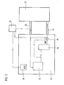
- the transducer (21) is again designed as an absolute position measuring system and corresponds in its basic structure to that of the exemplary embodiment explained above.
- the measured value pick-up (21) includes, among other things, a schematically represented measured value generation unit (25) and a memory module (26) with different memory areas (26.1, 26.2, 26.3).
- a comparator unit (27) is also arranged within the device according to the invention, which ensures a defined switching between the different operating modes by comparing the signals present on at least one signal transmission line (23) with reference signals of the respective activated operating mode is identified. In contrast to the illustrated embodiment of FIG.
- one of the two signal transmission lines (24) is now designed as a signal transmission line (24) which can be operated in a directional manner, which is indicated in a schematic form in FIG. 2.
- a switchover means (28) is activated.
- the switchover means (28) establishes the connection between the processing unit (22) and the writable and readable memory module (26) within the transducer (21).
- the user-specific programming of the memory module (26) or the writing and reading out of the different memory areas (62.1, 26.2, 26.3) then takes place via the bidirectionally operating signal transmission line (24).
- the reference signal for the comparator unit (27) via an oscillator stage (29) to generate the actual transducer (21) assigned.
- an external To supply the reference signal via the processing unit (22), which is shown in FIG 2 is also indicated.
- this exemplary embodiment corresponds to that of FIG. 1.
- both schematically illustrated Comparator unit (27) and the switching means (28) hard and / or software. Based on the selected representation should only explain the functional interaction according to the invention the different operating modes of the sensor enables; a limitation to certain embodiments of the individual components cannot be seen in it.
- a third embodiment of the device according to the invention or of the method according to the invention is explained below with reference to the schematic representation in FIG. While in the two exemplary embodiments described above there was a switchover between a measuring mode and a programming mode of a measuring sensor, the third exemplary embodiment provides for switching between different measuring modes of the measuring sensor (31) in a defined manner.
- the two measurement modes differ in the form of the signals transmitted to the downstream evaluation unit (32).
- Analog signals are transmitted in a first measurement mode, while digital signals are transmitted in the second measurement mode.
- Such a switchover option between different output signals of a measuring sensor (31) designed as a position measuring device proves to be advantageous, for example, for fault diagnosis if it is possible to switch from the usually rectangular output signals to the analog scanning signals for this purpose.
- a measurement value generation unit (35) is provided on the part of the measurement sensor (31), which is again designed, for example, as a position measurement device. These can be used to generate analog scanning signals by means of the photoelectric scanning of one or more code disks, which serve to determine the absolute position of two objects that are movable relative to one another.
- the measured value generation unit (35) can also be designed differently, for example for incremental position determination by photoelectric or magnetic scanning of a periodic scale division, etc. Accordingly, analog signals are generated via the measured value generation unit (35), which signals within the measured value sensor (31) get a signal processing stage (36).
- the signal processing stage (36) provided is used to convert the analog signals into digital signals, that is to say, for example, into corresponding output signals in rectangular form.
- the digital output signals are transferred to the downstream processing unit (32) via a signal transmission line (34).
- a further signal transmission line (33) is provided, via which, analogously to the first exemplary embodiment, clock signals are transmitted to the measured value generation unit (35) for the data transfer suitable to synchronize.
- at least one second measuring mode of the measuring sensor (31) is provided, which enables the analog scanning signals to be transferred to the processing unit (32).
- the corresponding analog signals are tapped between the measured value generation unit (35) and the signal processing stage (36).
- a suitable switchover means (38) is arranged between the signal transmission line (34) and the two signal lines on the side of the measuring sensor (31), on which the analog or digital signals are present, so that between analog or digital signals present on the output side can be selected, which are transferred to the processing unit (32).
- the corresponding switchover between the different measurement modes takes place analogously to the two exemplary embodiments explained above.
- a comparator unit (37) is again provided which is designed such that it is possible to detect the signal frequency present on the second signal transmission line (33). The signal frequency present is always compared, as previously explained, with a reference signal which is generated by an oscillator stage (39) which is assigned to the transducer (31).
- a defined reference frequency is in turn assigned to each of the two measurement modes, so that when a reference frequency of this type is recognized, the switchover means (38) can be used to switch to the corresponding measurement mode.
- the measures according to the invention consequently ensure that no separate connecting lines between the processing unit (32) and the sensor (31) are required in order to enable the desired switching between different operating modes.
- the exemplary embodiment shown in FIG. 3 shows only one possible variant of transducers in which such a switchover is possible.
- the measures according to the invention can also be used in a suitably modified manner in other transducers.
Landscapes
- Physics & Mathematics (AREA)
- General Physics & Mathematics (AREA)
- Arrangements For Transmission Of Measured Signals (AREA)
- Transmission And Conversion Of Sensor Element Output (AREA)
Applications Claiming Priority (2)
| Application Number | Priority Date | Filing Date | Title |
|---|---|---|---|
| DE19605763 | 1996-02-16 | ||
| DE19605763 | 1996-02-16 |
Publications (2)
| Publication Number | Publication Date |
|---|---|
| EP0790489A1 EP0790489A1 (de) | 1997-08-20 |
| EP0790489B1 true EP0790489B1 (de) | 2000-05-17 |
Family
ID=7785579
Family Applications (1)
| Application Number | Title | Priority Date | Filing Date |
|---|---|---|---|
| EP96120019A Expired - Lifetime EP0790489B1 (de) | 1996-02-16 | 1996-12-13 | Vorrichtung und Verfahren zur Umschaltung zwischen verschiedenen Betriebsmodi eines Messwertaufnehmers |
Country Status (4)
| Country | Link |
|---|---|
| US (1) | US6043768A (enExample) |
| EP (1) | EP0790489B1 (enExample) |
| JP (1) | JP3745856B2 (enExample) |
| DE (3) | DE59605246D1 (enExample) |
Families Citing this family (28)
| Publication number | Priority date | Publication date | Assignee | Title |
|---|---|---|---|---|
| DE19711215C1 (de) * | 1997-03-18 | 1998-05-07 | Heidenhain Gmbh Dr Johannes | Verfahren und Vorrichtung zur Umschaltung zwischen verschiedenen Ausgangssignal-Arten einer Positionsmeßeinrichtung |
| DE19811105C2 (de) * | 1998-03-13 | 2002-11-07 | Robert Rohrbach | Axial-Meßtaster |
| DE19964002A1 (de) | 1999-12-30 | 2001-07-12 | Micronas Gmbh | Sensor |
| DE10016712C5 (de) * | 2000-04-04 | 2004-09-16 | Pilz Gmbh & Co. | Sicherheitsschaltgerät und Verfahren zur Einstellung einer Betriebsart eines Sicherheitsschaltgeräts |
| GB0111482D0 (en) * | 2001-05-10 | 2001-07-04 | Fast Technology Ag | Data transfer protocol |
| DE10130307C2 (de) * | 2001-06-22 | 2003-08-21 | Siemens Ag | Verfahren und Schaltungsanordnung zur Auswertung von Sensorausgangssignalen |
| JP4868824B2 (ja) | 2005-07-29 | 2012-02-01 | パナソニック電工Sunx株式会社 | 検出センサ及びその設定情報取得方法 |
| JP4950452B2 (ja) * | 2005-07-29 | 2012-06-13 | パナソニック電工Sunx株式会社 | 検出センサ |
| JP4868823B2 (ja) * | 2005-09-16 | 2012-02-01 | パナソニック電工Sunx株式会社 | 検出センサ及びセンサシステム |
| DE202006006134U1 (de) * | 2006-04-12 | 2006-07-27 | Dr. Johannes Heidenhain Gmbh | Messsystem mit mindestens einer Sensorleitung |
| DE102006039295A1 (de) * | 2006-08-22 | 2008-03-13 | Knorr-Bremse Systeme für Nutzfahrzeuge GmbH | Anordnung zum Betrieb eines Sensors |
| US20080080083A1 (en) * | 2006-09-29 | 2008-04-03 | Homer Steven S | Methods and systems for a reader/writer selectively positionable inside and outside a chassis |
| US7411862B2 (en) * | 2006-11-15 | 2008-08-12 | Qimonda Ag | Control signal training |
| ES2375380T3 (es) * | 2007-01-19 | 2012-02-29 | Sick Stegmann Gmbh | Procedimiento y dispositivo para la fijación de parámetros de una instalación de medición. |
| US8730772B1 (en) * | 2007-08-10 | 2014-05-20 | Marvell International Ltd. | Minimization of VCM-resolution switching induced position error transients |
| DE102008034318B4 (de) * | 2008-07-23 | 2019-08-29 | Robert Bosch Gmbh | Anordnung zur Auswertung der Messwerte eines Messwertwandlers |
| DE102008053105A1 (de) * | 2008-10-24 | 2010-04-29 | Dr. Johannes Heidenhain Gmbh | Vorrichtung und Verfahren zur Datenübertragung zwischen einem Positionsmessgerät und einer Folgeelektronik |
| DE102008057474B4 (de) * | 2008-11-14 | 2012-08-02 | Kg Transmitter Components Gmbh | Meßumformer |
| DE102008054887B4 (de) * | 2008-12-18 | 2021-03-25 | Dr. Johannes Heidenhain Gmbh | Vorrichtung und Verfahren zur automatisierten Erkennung einer Schnittstelle |
| US8022715B2 (en) * | 2009-01-27 | 2011-09-20 | General Electric Company | Automated sensor specific calibration through sensor parameter download |
| JP5339057B2 (ja) * | 2009-01-28 | 2013-11-13 | 横河電機株式会社 | 測定装置 |
| GB0906257D0 (en) | 2009-04-08 | 2009-05-20 | Renishaw Plc | Position encoder apparatus |
| GB0906258D0 (en) * | 2009-04-08 | 2009-05-20 | Renishaw Plc | Position encoder apparatus |
| ES2732551T3 (es) | 2010-04-26 | 2019-11-25 | Nidec Avtron Automation Corp | Codificador absoluto |
| WO2013020528A1 (de) * | 2011-08-11 | 2013-02-14 | Balluff Gmbh | Messwert-übertragungsvorrichtung |
| DE102013208629A1 (de) * | 2013-05-10 | 2014-11-13 | Dr. Johannes Heidenhain Gmbh | Positionsmesseinrichtung |
| FR3035495B1 (fr) * | 2015-04-23 | 2017-05-26 | Meggitt (Sensorex) | Systeme de mesure des deplacements d'un organe mobile notamment d'un aeronef |
| JP7268426B2 (ja) * | 2019-03-20 | 2023-05-08 | 日本精工株式会社 | 回転角度検出器及びサーボモータシステム |
Family Cites Families (18)
| Publication number | Priority date | Publication date | Assignee | Title |
|---|---|---|---|---|
| CH645719A5 (de) * | 1980-10-28 | 1984-10-15 | Hans Guegler | Verfahren und einrichtung zur erfassung, aufzeichnung und auswertung von physikalischen messdaten. |
| NL8005976A (nl) * | 1980-10-31 | 1982-05-17 | Philips Nv | Tweedraads-bussysteem met een kloklijndraad en een datalijndraad voor het onderling verbinden van een aantal stations. |
| DE3270944D1 (en) * | 1981-02-27 | 1986-06-12 | Georges Hildebrand | Off-road amphibious motor vehicle |
| DE3561846D1 (en) | 1984-07-13 | 1988-04-14 | Stegmann Uhren Elektro | Arrangement for the serial transmission of measured values of at least one transducer |
| US4723122A (en) * | 1985-10-25 | 1988-02-02 | Drexelbrook Controls, Inc. | Remotely calibratable instrument system |
| US4849754A (en) * | 1985-10-25 | 1989-07-18 | Drexelbrook Controls | Remotely calibratable instrument system |
| GB2218213B (en) * | 1985-10-25 | 1990-07-04 | Drexelbrook Controls | Remotely calabratable instrument system and method of operation thereof |
| DE3540599A1 (de) * | 1985-11-15 | 1987-05-21 | Porsche Ag | Diagnosesystem fuer ein kraftfahrzeug |
| GB8528587D0 (en) | 1985-11-20 | 1985-12-24 | Drallim Ltd | Transducer interfaces |
| JPS62235504A (ja) * | 1986-04-04 | 1987-10-15 | Mitsutoyo Corp | 容量型位置測定トランスデユ−サ |
| US4745402A (en) * | 1987-02-19 | 1988-05-17 | Rca Licensing Corporation | Input device for a display system using phase-encoded signals |
| DE3742119A1 (de) * | 1987-12-11 | 1989-06-22 | Siemens Ag | Datenverarbeitungssystem |
| AT392709B (de) * | 1987-12-23 | 1991-05-27 | Kueng Martin Karl | Elektronische multiplizierschaltung |
| DE3743846A1 (de) * | 1987-12-23 | 1989-07-13 | Porsche Ag | Messwertaufnehmer |
| DE4020809C2 (de) * | 1990-06-29 | 1994-10-20 | Siemens Ag | Verfahren zum Informationsaustausch über einen seriellen Bus |
| DE4129577C2 (de) | 1991-09-06 | 1999-11-25 | Mueller Arnold Gmbh Co Kg | Meßsystem zur Drehwinkelmessung |
| US5438330A (en) * | 1991-10-28 | 1995-08-01 | Nikon Corporation | Absolute encoder |
| DE4342377B4 (de) | 1993-12-13 | 2010-08-12 | Dr. Johannes Heidenhain Gmbh | Anordnung und Verfahren zur seriellen Datenübertragung einer Positionsmeßeinrichtung |
-
1996
- 1996-12-13 DE DE59605246T patent/DE59605246D1/de not_active Expired - Lifetime
- 1996-12-13 EP EP96120019A patent/EP0790489B1/de not_active Expired - Lifetime
-
1997
- 1997-01-16 DE DE19701310A patent/DE19701310B4/de not_active Revoked
- 1997-01-16 DE DE29724854U patent/DE29724854U1/de not_active Expired - Lifetime
- 1997-02-10 JP JP02676297A patent/JP3745856B2/ja not_active Expired - Fee Related
- 1997-02-10 US US08/797,048 patent/US6043768A/en not_active Expired - Lifetime
Also Published As
| Publication number | Publication date |
|---|---|
| DE19701310B4 (de) | 2006-07-27 |
| DE59605246D1 (de) | 2000-06-21 |
| JPH09311052A (ja) | 1997-12-02 |
| DE29724854U1 (de) | 2004-11-18 |
| DE19701310A1 (de) | 1997-08-21 |
| EP0790489A1 (de) | 1997-08-20 |
| JP3745856B2 (ja) | 2006-02-15 |
| US6043768A (en) | 2000-03-28 |
Similar Documents
| Publication | Publication Date | Title |
|---|---|---|
| EP0790489B1 (de) | Vorrichtung und Verfahren zur Umschaltung zwischen verschiedenen Betriebsmodi eines Messwertaufnehmers | |
| DE19613884B4 (de) | Verfahren zur Übertragung von Informationen und hierzu geeignete Vorrichtung | |
| EP2098930B1 (de) | Überwachungssystem für einen Antrieb | |
| EP0866305B1 (de) | Verfahren und Vorrichtung zur Umschaltung zwischen verschiedenen Ausgangssignal-Arten einer Positionsmesseinrichtung | |
| EP1845501B1 (de) | Messsystem mit mindestens einer Sensorleitung | |
| EP0866391B1 (de) | Verfahren und Vorrichtung zur Übertragung von Daten zwischen einer Positionsmesseinrichtung und einer Auswerteeinheit | |
| DE3445617A1 (de) | Verfahren und anordnung zur seriellen uebertragung der digitalen messwerte eines messwertwandlers | |
| WO1998039838A1 (de) | Verfahren und vorrichtung zur aufrechterhaltung eines winkelgenauen gleichlaufs einzelner vernetzter antriebe eines dezentralen antriebssystems | |
| EP0805382A1 (de) | Diagnoseeinrichtung für elektronisch gesteuerte Maschine, deren Betriebszustände erfasst und nach vorgegebenen Schlüsseln verknüpft werden | |
| DE2602461C3 (enExample) | ||
| WO2001089966A1 (de) | Programmierbare sensoreinheit | |
| DE102014225867A1 (de) | Vorrichtung und Verfahren zur Überprüfung eines Arbeitstaktsignals einer Positionsmesseinrichtung | |
| DE29724698U1 (de) | Vorrichtung zur Umschaltung zwischen verschiedenen Betriebsmodi eines Meßwertaufnehmers | |
| EP1614990B2 (de) | Positionsmesseinrichtung und Verfahren zur Positionsmessung | |
| DE19711218C1 (de) | Verfahren und Vorrichtung zur Übertragung von Daten zwischen einer Positionsmeßeinrichtung und einer Auswerteeinheit | |
| DE3608397A1 (de) | System und einrichtung zur seriellen datenuebertragung | |
| EP1071019B1 (de) | Verfahren und Anordnung zur Datenübertragung zwischen verschiedenen Speichereinheiten von Positionsmesseinrichtungen | |
| DE20214764U1 (de) | Schalteinrichtung zur Ansteuerung wenigstens zweier Motoren | |
| DE3305547A1 (de) | Schaltungsanordnung zum digitalen umwandeln eines analogen signals | |
| EP4310609B1 (de) | Datenbereitstellungsvorrichtung | |
| DE4113224C2 (enExample) | ||
| DE10130307C2 (de) | Verfahren und Schaltungsanordnung zur Auswertung von Sensorausgangssignalen | |
| DE2557944A1 (de) | Anordnung zur erzeugung eines austastsignals fuer die registerregelung | |
| EP1546658A1 (de) | Verfahren zum betrieb einer positionsmesseinrichtung und geeignete positionsmesseinrichtung hierzu | |
| DE29721478U1 (de) | Vorrichtung zur Übertragung von Daten zwischen einer Positionsmeßeinrichtung und einer Auswerteeinheit |
Legal Events
| Date | Code | Title | Description |
|---|---|---|---|
| PUAI | Public reference made under article 153(3) epc to a published international application that has entered the european phase |
Free format text: ORIGINAL CODE: 0009012 |
|
| AK | Designated contracting states |
Kind code of ref document: A1 Designated state(s): DE FR GB IT |
|
| 17P | Request for examination filed |
Effective date: 19980220 |
|
| 17Q | First examination report despatched |
Effective date: 19980724 |
|
| GRAG | Despatch of communication of intention to grant |
Free format text: ORIGINAL CODE: EPIDOS AGRA |
|
| GRAG | Despatch of communication of intention to grant |
Free format text: ORIGINAL CODE: EPIDOS AGRA |
|
| GRAH | Despatch of communication of intention to grant a patent |
Free format text: ORIGINAL CODE: EPIDOS IGRA |
|
| GRAH | Despatch of communication of intention to grant a patent |
Free format text: ORIGINAL CODE: EPIDOS IGRA |
|
| ITF | It: translation for a ep patent filed | ||
| GRAA | (expected) grant |
Free format text: ORIGINAL CODE: 0009210 |
|
| AK | Designated contracting states |
Kind code of ref document: B1 Designated state(s): DE FR GB IT |
|
| ET | Fr: translation filed | ||
| REF | Corresponds to: |
Ref document number: 59605246 Country of ref document: DE Date of ref document: 20000621 |
|
| GBT | Gb: translation of ep patent filed (gb section 77(6)(a)/1977) |
Effective date: 20000707 |
|
| PLBE | No opposition filed within time limit |
Free format text: ORIGINAL CODE: 0009261 |
|
| STAA | Information on the status of an ep patent application or granted ep patent |
Free format text: STATUS: NO OPPOSITION FILED WITHIN TIME LIMIT |
|
| 26N | No opposition filed | ||
| REG | Reference to a national code |
Ref country code: GB Ref legal event code: IF02 |
|
| REG | Reference to a national code |
Ref country code: DE Ref legal event code: R008 Ref document number: 59605246 Country of ref document: DE |
|
| REG | Reference to a national code |
Ref country code: DE Ref legal event code: R039 Ref document number: 59605246 Country of ref document: DE Effective date: 20110222 |
|
| REG | Reference to a national code |
Ref country code: DE Ref legal event code: R097 Ref document number: 59605246 Country of ref document: DE |
|
| PGFP | Annual fee paid to national office [announced via postgrant information from national office to epo] |
Ref country code: IT Payment date: 20121227 Year of fee payment: 17 Ref country code: GB Payment date: 20121220 Year of fee payment: 17 |
|
| PGFP | Annual fee paid to national office [announced via postgrant information from national office to epo] |
Ref country code: FR Payment date: 20130130 Year of fee payment: 17 |
|
| REG | Reference to a national code |
Ref country code: DE Ref legal event code: R040 Ref document number: 59605246 Country of ref document: DE Effective date: 20120712 |
|
| GBPC | Gb: european patent ceased through non-payment of renewal fee |
Effective date: 20131213 |
|
| REG | Reference to a national code |
Ref country code: FR Ref legal event code: ST Effective date: 20140829 |
|
| PG25 | Lapsed in a contracting state [announced via postgrant information from national office to epo] |
Ref country code: FR Free format text: LAPSE BECAUSE OF NON-PAYMENT OF DUE FEES Effective date: 20131231 Ref country code: GB Free format text: LAPSE BECAUSE OF NON-PAYMENT OF DUE FEES Effective date: 20131213 |
|
| PGFP | Annual fee paid to national office [announced via postgrant information from national office to epo] |
Ref country code: DE Payment date: 20141211 Year of fee payment: 19 |
|
| PG25 | Lapsed in a contracting state [announced via postgrant information from national office to epo] |
Ref country code: IT Free format text: LAPSE BECAUSE OF NON-PAYMENT OF DUE FEES Effective date: 20131231 |
|
| PG25 | Lapsed in a contracting state [announced via postgrant information from national office to epo] |
Ref country code: IT Free format text: LAPSE BECAUSE OF NON-PAYMENT OF DUE FEES Effective date: 20131213 |
|
| REG | Reference to a national code |
Ref country code: DE Ref legal event code: R119 Ref document number: 59605246 Country of ref document: DE |
|
| PG25 | Lapsed in a contracting state [announced via postgrant information from national office to epo] |
Ref country code: DE Free format text: LAPSE BECAUSE OF NON-PAYMENT OF DUE FEES Effective date: 20160701 |