EP0789467A2 - Méthode et dispositif de corrélation - Google Patents
Méthode et dispositif de corrélation Download PDFInfo
- Publication number
- EP0789467A2 EP0789467A2 EP97300744A EP97300744A EP0789467A2 EP 0789467 A2 EP0789467 A2 EP 0789467A2 EP 97300744 A EP97300744 A EP 97300744A EP 97300744 A EP97300744 A EP 97300744A EP 0789467 A2 EP0789467 A2 EP 0789467A2
- Authority
- EP
- European Patent Office
- Prior art keywords
- correlation
- register
- signal
- correlator
- values
- Prior art date
- Legal status (The legal status is an assumption and is not a legal conclusion. Google has not performed a legal analysis and makes no representation as to the accuracy of the status listed.)
- Withdrawn
Links
Images


Classifications
-
- G—PHYSICS
- G06—COMPUTING; CALCULATING OR COUNTING
- G06F—ELECTRIC DIGITAL DATA PROCESSING
- G06F17/00—Digital computing or data processing equipment or methods, specially adapted for specific functions
- G06F17/10—Complex mathematical operations
- G06F17/15—Correlation function computation including computation of convolution operations
-
- H—ELECTRICITY
- H04—ELECTRIC COMMUNICATION TECHNIQUE
- H04L—TRANSMISSION OF DIGITAL INFORMATION, e.g. TELEGRAPHIC COMMUNICATION
- H04L7/00—Arrangements for synchronising receiver with transmitter
- H04L7/04—Speed or phase control by synchronisation signals
- H04L7/041—Speed or phase control by synchronisation signals using special codes as synchronising signal
- H04L7/042—Detectors therefor, e.g. correlators, state machines
Definitions
- the invention concerns a method of determining the current correlation between a digitized signal and a predetermined correlation word as well as a correlator therefor. Finally, the invention concerns a portable telephone having such a correlator.
- the data burst comprises a preamble which contains information on the clock frequency of the data burst and a predetermined sync word, on the basis of which the start time of the successive data signal may be estimated.
- the preamble consists of sixteen data bit periods and a sync word likewise having sixteen data bit periods.
- the preamble is usually affected by noise, in particular jitter, for which reason the current values of the analog signal cannot readily be used in the calculation of the correlation with a predetermined correlation word.
- the received GMSK-modulated signal is FM-detected and passed to a comparator in which the signal is one-bit quantized. Then the formed signal is oversampled to form a string of discrete signal values which are used in the correlation with the correlation word.
- the correlation word contains 54 discrete data values or samples which are to be stored in respective cells in a correlation word register.
- the oversampled and quantized signal is passed to a register having a corresponding length (54 cells), and then the correlation is determined by multiplying the cells of the registers in pairs and subsequently summing them to determine the current correlation. It will be appreciated that the calculation involves many exacting arithmetical operations. Further, the storage space requirement is quite high partly for the temporary storage of the preamble signal, partly for the storage of the correlation word.
- the invention provides a method of determining the current correlation between a digitized signal and a predetermined correlation word, said correlation word comprising individual correlation values arranged in a plurality of successive correlation value groups, said correlation values within the respective correlation value groups assuming the same value, and wherein discrete signal values of the digitized signal, under the control of a clock, are caused to pass through a register means whose register cells are arranged in groups corresponding to the correlation value groups of the correlation word, wherein the digital signal values are output from the register cells which receive signal values from a preceding register cell group by a clock pulse, and wherein the current correlation is calculated by correcting a correlation, calculated for the former clock period, by a value which depends on the output signal values from the register cells combined with predetermined weight factors associated with respective register cells from which the signal values are output and a correlator for determining the current correlation between a digitized signal and a predetermined correlation word, said correlation word comprising individual correlation values arranged in a plurality of successive correlation value groups, said correlation values within respective
- the correlation word may be considered as a string of discrete values which may be divided into successive groups having the same discrete value.
- the discrete signal values of the digitized signal are caused to pass through a register under the control of a clock.
- the successive register cells of the register are arranged in groups corresponding to the groups of the correlation word, and the digital signal values are output from the register cells which, by a clock pulse, receive signal values from a preceding register cell group, i.e. from the first cell in each group.
- the output signal values are used in the calculation of a correlation change, and the current correlation is calculated by correcting a correlation, calculated from the previous clock period, by a value which depends on the output signal values combined with predetermined weight factors associated with respective register cells from which the signal values are output.
- the invention provides a method which enables the current correlation to be determined on the basis of a relatively few calculating operations, and which may be used in a consumer product, such as a digital cordless telephone with a minimum of storage space.
- the invention moreover concerns a correlator for determining the current correlation between a digitized signal and a predetermined correlation word.
- the correlation word may be considered as a string of discrete values which may be divided into successive groups having the same discrete value.
- the correlator comprises a register means through which the signal values of the digitized signal are caused to pass under the control of a clock.
- the register cells of the register means are arranged in groups corresponding to the correlation value groups of the correlation word and comprise outputs for outputting the contents from the register cells in the register means which, by a clock pulse, receive signal values from a preceding register cell group.
- An associated calculating device is used for calculating the current correlation, and this is determined on the basis of a correlation calculated for the previous clock period and corrected by a value which depends on the output signal values from the register cells combined with predetermined weight factors associated with respective cells from which the signal values are output. It is hereby possible to avoid storing the correlation word in its entirety, since it is just the difference between the values of the groups of the correlation word which is important in the calculation of the current correlation. The required number of register locations is hereby minimized, which means a drop of about 40 % in the preferred embodiment. This is of great importance since the space on the silicon chip is usually very restricted.
- the invention concerns a portable telephone containing a correlator of the type defined in claims 2-9 for use in the regeneration of the clock signal for a data burst in accordance with the DECT standard according to ETSI, said regeneration being performed by means of a periodic preamble signal in the data burst.
- Successive values in a correlation signal may hereby be used for determining the optimum sampling time in the sampling of the digital information contained in the data burst.
- this information comprises the sync word and the actual data signal.
- DECT signals are transmitted in TDMA channels as data bursts.
- the data burst forwardly has a preamble by which the receiver can detect the frequency of the signal and regenerate the clock frequency of the received signal. It has been found most expedient in a one-bit quantization to perform the sampling centrally in a data bit, and, therefore, the purpose of the clock frequency regeneration is essentially to find the centre of the data bits.
- the preamble is followed by a sync word which is used for determining the time of arrival of the first data bit and for estimating the time of arrival of the next data burst.
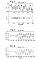
- the signal is frequency-modulated, the horizontal axis representing the time - here shown as the number of samples in an oversampling of the signal by a factor of nine, the vertical axis representing the frequency sweep as a function of time.
- the carrier wave in the DECT system is at about 1890 MHz, while the frequency sweep in the preamble with noise is within +/- 300 kHz.
- the preamble has a data bit rate of 1152 kbits/sec. in the DECT system.
- the preamble is located from sample about no. 60 to sample about no. 200 in the signal sequence shown and comprises 16 data bit periods.
- the top signal shown in fig. 2 corresponds to the one supplied from the FM detector of the telephone.
- the signal is one-bit quantized in a comparator, as a conventional A/D converter uses too much power and is too expensive to lend itself for use in a cordless telephone.
- the quantized signal is oversampled by a factor of 9 (9 samples in each data bit period), which means here that the sample frequency will be 10,368 MHz, which corresponds to the system clock of the cordless telephone.
- the purpose of adjusting the receiver to the clock frequency of the transmitter is to ensure that received data are sampled precisely in the centre, it having been found that the optimum ratio of signal to noise is achieved hereby.
- the correlation word will usually be preselected as a segment of the quantized preamble signal.
- the length of the correlation word is selected as compromise between the desirability of detecting the presence of the preamble signal with the greatest possible probability without simultaneously risking latching to false preamble signals, which requires correlation words as long as possible, and the desirability of e.g. being able to correct DC errors at the beginning of the reception of the preamble signal and subsequently being able to latch to the rest of the preamble signal. This usually requires a relatively short correlation word.
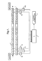
- the length of the correlation word is selected to correspond to six data bit periods in the preamble signal. Since an oversampling factor of nine has simultaneously been selected, the correlation word will have a length of 54 bits. It is illustrated in fig. 1 how an arriving, quantized signal is correlated with the correlation word.
- the correlation word is stored in a register 1 having 54 register locations c n , while the arriving, quantized signal, under the control of the sample clock signal, is clocked into a first-in-first-out register 2 having register locations a n corresponding to the correlation word register 1.
- the contents of the individual register locations a n and c n are clocked out, and the contents are passed to multiplication devices 3 n , which are associated with respective register locations, the number of these being therefore 54.
- the contents of the register location a o are multiplied by the contents of the register location c o , etc. in the multiplication device 3 o .
- the 54 products calculated in the multiplication devices 3 n are passed to a summation device 4, in which the products are summed, and a sum result 5 may be output from the summation device 4 as a representation of the current or instantaneous correlation between the quantized signal and the correlation word.
- the invention is based on the finding that a noiseless preamble signal, when quantized and oversampled with a factor S, will assume the shape of a string of bits which are grouped, so that a group in the form of a sequence of S bits with a logic state "1" is followed by a sequence of S bits having a logic state "0", which is repeated periodically.
- This is followed by the register locations c 9 -c 17 of the correlation word which, as a group, then assume a logic state "0".
- the contents of the register locations of the correlation word may be considered as a sort of weight factor by which the individual bits of the arriving signal are weighted in the calculation of the current correlation.
- the current correlation may be calculated by adding a modifier value to the previous correlation.
- the modifier value is determined by multiplying the contents or the value of the bits changing weight factor by the weight factor modification, i.e. the new weight factor minus the old weight factor.
- seven bits change weight factor - viz. the five changing from one group to another and two which are received in the first group and which leave the last group, respectively.
- the intermediate register locations thus just serve to store and delay samples which are not used in the calculation of a modifier value in a given clock period.
- Fig. 3 shows a preferred embodiment of a correlator of the invention.
- the correlator comprises a register 2' which operates according to the first-in-first-out principle and corresponds to the register 2 shown in fig. 1, said register 2' having one extra register location a 54 , the register locations then totalling 55.
- This extra register location receives the bit which leaves the last weight factor group, and which is included in the calculation of the correlation modifier value.
- the bits which changed weight factor at the last clock pulse are present on the register locations a o , a 9 , a 18 , a 27 , a 36 , a 45 and a 54 .
- the logic "1" is represented by the value 1
- the logic "0" is represented by the value -1.
- the weight factor of samples present outside the register 2' and thus the correlation word will be 0.
- the weight factor of the register locations c o -c 8 , c 18 -c 26 , and c 36 -c 44 will be + 1, while it will be -1 for the register locations c 9 -c 17 , c 27 -c 35 and c 45 -c 53 .
- the weight factor modifications are stored in seven registers 6.
- the contents of the register locations a o , a 9 , a 18 , a 27 , a 36 , a 45 and a 54 are output and passed to respective multiplication devices 7, in which the register contents are multiplied by the weight factor modifications stored in the registers 6.
- the products from the multiplication devices 7 are passed to a summation device 8, in which the modifier value for the correlation is calculated by adding the products calculated in the multiplication devices 7 with each other.
- the modifier value for the correlation is passed further on to another summation device 9, in which the modifier value for the correlation is summed with the correlation value of the former clock period.
- the current correlation 11 may be output from the summation device 9, and the calculated value is simultaneously stored on the former value in a register 10, from which the value may be output in the next clock period as the correlation value of the former clock period for use in the summation device 9.
- the summation device 9 may be omitted, if the contents of the register 10 are instead returned directly to the summation device 8. The modifier value for the correlation will then not appear as an intermediate result.
- Fig. 4 shows an alternative embodiment of a correlator of the invention, and this embodiment, like the one shown in fig. 3, has a register 2' which operates according to the first-in-first-out principle, and which has one extra register location a 54 , the number of storage locations then totalling 55. Since the correlation word is the same for the alternative embodiment, the bits changing weight factor by a clock pulse are present on the same register locations - viz. the locations a o , a 9 , a 18 , a 27 , a 36 , a 45 and a 54 . This embodiment utilizes the fact that the weight factor change with which the seven bits are associated is known beforehand.
- the contents of the register locations a o and a 54 are output by the sampling clock signal, and the contents are passed to a first summation device 12, from which the sum is passed to a first multiplication device 13 in which said is multiplied by the respective weight factor change stored in a register 6.
- the contents of the register locations a 9 , a 27 , a 45 and of the register locations a 18 , a 36 , respectively are output and passed to a second and a third summation device 14, 16, respectively, from which the sum is passed to a second and a third multiplication device 15, 17, respectively, in which said sums are multiplied by the respective weight factor change stored in registers 6.
- the products from the three summation devices 12, 14 and 16 are transferred to a counter 18, which contains the value of the last-calculated correlation.
- the three products correct the contents of the counter by the calculated correlation modifier contributions, and then the current correlation 11 is accessible on the output of the counter 18.
- the modifier value for the correlation will not be readily accessible as an intermediate result anywhere in the correlator, as the counter 18 here replaces the summation devices 8 and 9 in the first embodiment.
- Fig. 5 shows a correlation signal generated on the basis of an optimum noiseless preamble signal which has been quantized as described above and correlated with the correlator shown in fig. 3.
- the correlator acts as a Fir filter having pass band properties. This results in the formation of the correlation signal shown in fig. 5, which has a rated maximum and minimum at an amplitude of +/-27.
- the reason is that the arrived signal is represented by the amplitude 1 for logic "1" and 0 for logic "0". If, instead, the arrived signal was represented by the amplitude 1 for logic "1" and -1 for logic "0", the amplitude time values of the correlation signal would be positioned at +/-54 (the number of bits in the correlation word).
- the horizontal, dotted lines indicate possible threshold values to detect a good correlation between signal and correlation word.
- the invention provides a correlator where the register 1 for containing the correlation word may be replaced by registers 6 containing weight factor modifications. If the invention is implemented as illustrated by the described embodiments, a saving as high as about 40 % of the total silicon area can be achieved over a correlator implemented as shown in fig. 1. Another quite essential advantage is that the amount of calculating operations is reduced significantly, as just quite few bits are included in the calculations. In particular, the many calculating power consuming multiplifications are avoided. Further, the two embodiments shown are unique in that the oversampling factor may be made arbitrarily great without changing the number of calculating operations per calculated correlation, since it is the number of weight factor groups in the correlation word which controls that number.
- the invention may be implemented both in software and hardware. The actual implementation depends on the contemplated application of the correlator. When used in connection with cordless telephones, the invention may advantageously be implemented together with a clock regeneration module in a special chip.
- the present invention includes any novel feature or combination of features disclosed herein either explicitly or any generalisation thereof irrespective of whether or not it relates to the claimed invention or mitigates any or all of the problems addressed.
Applications Claiming Priority (2)
| Application Number | Priority Date | Filing Date | Title |
|---|---|---|---|
| GB9602566 | 1996-02-08 | ||
| GB9602566A GB2310056A (en) | 1996-02-08 | 1996-02-08 | Correlator |
Publications (1)
| Publication Number | Publication Date |
|---|---|
| EP0789467A2 true EP0789467A2 (fr) | 1997-08-13 |
Family
ID=10788349
Family Applications (1)
| Application Number | Title | Priority Date | Filing Date |
|---|---|---|---|
| EP97300744A Withdrawn EP0789467A2 (fr) | 1996-02-08 | 1997-02-05 | Méthode et dispositif de corrélation |
Country Status (2)
| Country | Link |
|---|---|
| EP (1) | EP0789467A2 (fr) |
| GB (1) | GB2310056A (fr) |
Cited By (3)
| Publication number | Priority date | Publication date | Assignee | Title |
|---|---|---|---|---|
| WO2000054424A3 (fr) * | 1999-03-05 | 2001-02-01 | Ericsson Telefon Ab L M | Procede et appareil de synchronisation efficace dans des communications a spectre etale |
| WO2001047140A2 (fr) * | 1999-12-20 | 2001-06-28 | Infineon Technologies Ag | Procede et dispositif de synchronisation d'un recepteur mobile avec une structure trame d'un signal radio |
| FR2898998A1 (fr) * | 2006-03-21 | 2007-09-28 | Thales Sa | Procede et dispositif de calcul de correlation rapide |
Family Cites Families (2)
| Publication number | Priority date | Publication date | Assignee | Title |
|---|---|---|---|---|
| CA1063729A (fr) * | 1976-06-01 | 1979-10-02 | James W. Smith | Correlateur de champ |
| GB2023316B (en) * | 1978-06-16 | 1982-09-22 | Henry R M | Correlation system |
-
1996
- 1996-02-08 GB GB9602566A patent/GB2310056A/en not_active Withdrawn
-
1997
- 1997-02-05 EP EP97300744A patent/EP0789467A2/fr not_active Withdrawn
Non-Patent Citations (1)
| Title |
|---|
| None |
Cited By (11)
| Publication number | Priority date | Publication date | Assignee | Title |
|---|---|---|---|---|
| WO2000054424A3 (fr) * | 1999-03-05 | 2001-02-01 | Ericsson Telefon Ab L M | Procede et appareil de synchronisation efficace dans des communications a spectre etale |
| US6567482B1 (en) | 1999-03-05 | 2003-05-20 | Telefonaktiebolaget Lm Ericsson (Publ) | Method and apparatus for efficient synchronization in spread spectrum communications |
| AU770399B2 (en) * | 1999-03-05 | 2004-02-19 | Telefonaktiebolaget Lm Ericsson (Publ) | Method and apparatus for efficient synchronization in spread spectrum communications |
| KR100726050B1 (ko) * | 1999-03-05 | 2007-06-08 | 텔레폰악티에볼라겟엘엠에릭슨(펍) | 스프레드 스펙트럼 통신에서 효율적인 동기화 방법 및 장치 |
| CN1367965B (zh) * | 1999-03-05 | 2013-05-01 | 艾利森电话股份有限公司 | 在扩频通信中实现同步的方法和设备 |
| WO2001047140A2 (fr) * | 1999-12-20 | 2001-06-28 | Infineon Technologies Ag | Procede et dispositif de synchronisation d'un recepteur mobile avec une structure trame d'un signal radio |
| WO2001047140A3 (fr) * | 1999-12-20 | 2002-02-14 | Infineon Technologies Ag | Procede et dispositif de synchronisation d'un recepteur mobile avec une structure trame d'un signal radio |
| US7133424B2 (en) | 1999-12-20 | 2006-11-07 | Infineon Technologies Ag | Method and device for synchronizing a mobile radio receiver with a time slot structure of a received radio signal |
| FR2898998A1 (fr) * | 2006-03-21 | 2007-09-28 | Thales Sa | Procede et dispositif de calcul de correlation rapide |
| WO2007107445A3 (fr) * | 2006-03-21 | 2008-03-06 | Thales Sa | Procede et dispositif de calcul de correlation rapide |
| US8301678B2 (en) | 2006-03-21 | 2012-10-30 | Thales | Method and device for fast correlation calculation |
Also Published As
| Publication number | Publication date |
|---|---|
| GB2310056A (en) | 1997-08-13 |
| GB9602566D0 (en) | 1996-04-10 |
Similar Documents
| Publication | Publication Date | Title |
|---|---|---|
| CA1181857A (fr) | Processeur de paroles identifiant les silences | |
| US4185172A (en) | Method of and means for detecting digitized multi frequency-coded signals | |
| US5907587A (en) | Method and apparatus for clock recovery | |
| CA2120598A1 (fr) | Systeme et methode de detection de signaux d'emission | |
| EP0045801B1 (fr) | Detecteur de tonalite numerique pseudo continu | |
| EP0088771B1 (fr) | Interpolateur a croisement zero permettant de reduire la distorsion isochrone dans un modem numerique a modulation par deplacement de frequence | |
| JPS59100643A (ja) | 電話チャンネルのノイズレベル判定装置 | |
| CA1250024A (fr) | Detection de tonalite audio pour fins de surveillance dans un canal de radiocommunication | |
| US4719649A (en) | Autoregressive peek-through comjammer and method | |
| EP0004759B1 (fr) | Procédé et dispositif pour coder et reconstituer des signaux | |
| GB2361854A (en) | Detection of mutually orthogonal codewords, with intersymbol interference and imperfect timing | |
| EP0523307B1 (fr) | Filtre numérique à décimation pour convertisseur sigma-delta et équipement terminal de données comprenant un tel filtre | |
| US5495526A (en) | Tone-detection method for detecting at least one tone in a dual-tone multifrequency signal, call-progress method using the same | |
| EP0789467A2 (fr) | Méthode et dispositif de corrélation | |
| EP0044402B1 (fr) | Système de synchronisation pour données numériques | |
| US4206323A (en) | Dual tone multifrequency signal receiver | |
| US5304990A (en) | Modular analyzer of digital signal traffic | |
| JP2531118B2 (ja) | 自動周波数制御装置 | |
| EP0770311B1 (fr) | Systeme de transmission avec detection de tonalite amelioree | |
| US4499594A (en) | Digital to analog converter | |
| EP0167364A1 (fr) | Détection parole-silence avec codage par sous-bandes | |
| US5276708A (en) | Coding method for reducing the D.C. component in the data stream of a digital signal | |
| MY125022A (en) | Partial response maximum likelihood (prml) bit detection apparatus | |
| US4617427A (en) | Square root circuit | |
| WO2001017278A2 (fr) | Circuit et procede servant a detecter une tonalite |
Legal Events
| Date | Code | Title | Description |
|---|---|---|---|
| PUAI | Public reference made under article 153(3) epc to a published international application that has entered the european phase |
Free format text: ORIGINAL CODE: 0009012 |
|
| AK | Designated contracting states |
Kind code of ref document: A2 Designated state(s): DE FR GB SE |
|
| STAA | Information on the status of an ep patent application or granted ep patent |
Free format text: STATUS: THE APPLICATION HAS BEEN WITHDRAWN |
|
| 18W | Application withdrawn |
Withdrawal date: 20000816 |