EP0789405A2 - Verfahren zum Abkühlen von Sonnenzellen - Google Patents
Verfahren zum Abkühlen von Sonnenzellen Download PDFInfo
- Publication number
- EP0789405A2 EP0789405A2 EP97100553A EP97100553A EP0789405A2 EP 0789405 A2 EP0789405 A2 EP 0789405A2 EP 97100553 A EP97100553 A EP 97100553A EP 97100553 A EP97100553 A EP 97100553A EP 0789405 A2 EP0789405 A2 EP 0789405A2
- Authority
- EP
- European Patent Office
- Prior art keywords
- solar cell
- cooling
- coolant
- light receiving
- receiving surface
- Prior art date
- Legal status (The legal status is an assumption and is not a legal conclusion. Google has not performed a legal analysis and makes no representation as to the accuracy of the status listed.)
- Withdrawn
Links
- 238000001816 cooling Methods 0.000 title claims abstract description 57
- 238000000034 method Methods 0.000 title claims abstract description 30
- 239000002826 coolant Substances 0.000 claims abstract description 50
- 239000000463 material Substances 0.000 claims abstract description 11
- FAPWRFPIFSIZLT-UHFFFAOYSA-M Sodium chloride Chemical compound [Na+].[Cl-] FAPWRFPIFSIZLT-UHFFFAOYSA-M 0.000 claims description 6
- 239000007864 aqueous solution Substances 0.000 claims description 6
- TZCXTZWJZNENPQ-UHFFFAOYSA-L barium sulfate Chemical compound [Ba+2].[O-]S([O-])(=O)=O TZCXTZWJZNENPQ-UHFFFAOYSA-L 0.000 claims description 6
- 239000004065 semiconductor Substances 0.000 claims description 4
- 238000004519 manufacturing process Methods 0.000 claims description 3
- 239000011780 sodium chloride Substances 0.000 claims description 3
- 239000007921 spray Substances 0.000 claims description 3
- 239000010409 thin film Substances 0.000 claims description 2
- 230000000694 effects Effects 0.000 description 16
- XLYOFNOQVPJJNP-UHFFFAOYSA-N water Substances O XLYOFNOQVPJJNP-UHFFFAOYSA-N 0.000 description 14
- 238000010586 diagram Methods 0.000 description 8
- 230000001965 increasing effect Effects 0.000 description 8
- 230000007423 decrease Effects 0.000 description 7
- 239000000758 substrate Substances 0.000 description 5
- 239000012780 transparent material Substances 0.000 description 5
- 239000010408 film Substances 0.000 description 4
- 239000000969 carrier Substances 0.000 description 3
- 229910021421 monocrystalline silicon Inorganic materials 0.000 description 3
- CSCPPACGZOOCGX-UHFFFAOYSA-N Acetone Chemical compound CC(C)=O CSCPPACGZOOCGX-UHFFFAOYSA-N 0.000 description 2
- 238000010521 absorption reaction Methods 0.000 description 2
- 239000000498 cooling water Substances 0.000 description 2
- 230000007797 corrosion Effects 0.000 description 2
- 238000005260 corrosion Methods 0.000 description 2
- 238000009826 distribution Methods 0.000 description 2
- 239000011521 glass Substances 0.000 description 2
- 238000007654 immersion Methods 0.000 description 2
- 238000012986 modification Methods 0.000 description 2
- 230000004048 modification Effects 0.000 description 2
- 238000002161 passivation Methods 0.000 description 2
- 239000011347 resin Substances 0.000 description 2
- 229920005989 resin Polymers 0.000 description 2
- 229910004613 CdTe Inorganic materials 0.000 description 1
- 229910001218 Gallium arsenide Inorganic materials 0.000 description 1
- LRHPLDYGYMQRHN-UHFFFAOYSA-N N-Butanol Chemical compound CCCCO LRHPLDYGYMQRHN-UHFFFAOYSA-N 0.000 description 1
- XUIMIQQOPSSXEZ-UHFFFAOYSA-N Silicon Chemical compound [Si] XUIMIQQOPSSXEZ-UHFFFAOYSA-N 0.000 description 1
- 230000003466 anti-cipated effect Effects 0.000 description 1
- 238000013459 approach Methods 0.000 description 1
- 229910052980 cadmium sulfide Inorganic materials 0.000 description 1
- 150000001875 compounds Chemical class 0.000 description 1
- 238000010276 construction Methods 0.000 description 1
- 229910021419 crystalline silicon Inorganic materials 0.000 description 1
- 230000003247 decreasing effect Effects 0.000 description 1
- 230000006866 deterioration Effects 0.000 description 1
- 238000002474 experimental method Methods 0.000 description 1
- 239000012535 impurity Substances 0.000 description 1
- 230000001939 inductive effect Effects 0.000 description 1
- 239000011810 insulating material Substances 0.000 description 1
- 230000001678 irradiating effect Effects 0.000 description 1
- 230000031700 light absorption Effects 0.000 description 1
- 239000007788 liquid Substances 0.000 description 1
- 229910052751 metal Inorganic materials 0.000 description 1
- 239000002184 metal Substances 0.000 description 1
- 229910021420 polycrystalline silicon Inorganic materials 0.000 description 1
- 238000011084 recovery Methods 0.000 description 1
- 238000004904 shortening Methods 0.000 description 1
- 229910052710 silicon Inorganic materials 0.000 description 1
- 239000010703 silicon Substances 0.000 description 1
- 238000005507 spraying Methods 0.000 description 1
- 238000009834 vaporization Methods 0.000 description 1
- 230000008016 vaporization Effects 0.000 description 1
Images

Classifications
-
- H—ELECTRICITY
- H10—SEMICONDUCTOR DEVICES; ELECTRIC SOLID-STATE DEVICES NOT OTHERWISE PROVIDED FOR
- H10F—INORGANIC SEMICONDUCTOR DEVICES SENSITIVE TO INFRARED RADIATION, LIGHT, ELECTROMAGNETIC RADIATION OF SHORTER WAVELENGTH OR CORPUSCULAR RADIATION
- H10F77/00—Constructional details of devices covered by this subclass
- H10F77/10—Semiconductor bodies
- H10F77/14—Shape of semiconductor bodies; Shapes, relative sizes or dispositions of semiconductor regions within semiconductor bodies
- H10F77/148—Shapes of potential barriers
-
- H—ELECTRICITY
- H10—SEMICONDUCTOR DEVICES; ELECTRIC SOLID-STATE DEVICES NOT OTHERWISE PROVIDED FOR
- H10F—INORGANIC SEMICONDUCTOR DEVICES SENSITIVE TO INFRARED RADIATION, LIGHT, ELECTROMAGNETIC RADIATION OF SHORTER WAVELENGTH OR CORPUSCULAR RADIATION
- H10F77/00—Constructional details of devices covered by this subclass
- H10F77/40—Optical elements or arrangements
- H10F77/42—Optical elements or arrangements directly associated or integrated with photovoltaic cells, e.g. light-reflecting means or light-concentrating means
- H10F77/484—Refractive light-concentrating means, e.g. lenses
-
- H—ELECTRICITY
- H10—SEMICONDUCTOR DEVICES; ELECTRIC SOLID-STATE DEVICES NOT OTHERWISE PROVIDED FOR
- H10F—INORGANIC SEMICONDUCTOR DEVICES SENSITIVE TO INFRARED RADIATION, LIGHT, ELECTROMAGNETIC RADIATION OF SHORTER WAVELENGTH OR CORPUSCULAR RADIATION
- H10F77/00—Constructional details of devices covered by this subclass
- H10F77/60—Arrangements for cooling, heating, ventilating or compensating for temperature fluctuations
- H10F77/63—Arrangements for cooling directly associated or integrated with photovoltaic cells, e.g. heat sinks directly associated with the photovoltaic cells or integrated Peltier elements for active cooling
- H10F77/68—Arrangements for cooling directly associated or integrated with photovoltaic cells, e.g. heat sinks directly associated with the photovoltaic cells or integrated Peltier elements for active cooling using gaseous or liquid coolants, e.g. air flow ventilation or water circulation
-
- H—ELECTRICITY
- H10—SEMICONDUCTOR DEVICES; ELECTRIC SOLID-STATE DEVICES NOT OTHERWISE PROVIDED FOR
- H10F—INORGANIC SEMICONDUCTOR DEVICES SENSITIVE TO INFRARED RADIATION, LIGHT, ELECTROMAGNETIC RADIATION OF SHORTER WAVELENGTH OR CORPUSCULAR RADIATION
- H10F77/00—Constructional details of devices covered by this subclass
- H10F77/70—Surface textures, e.g. pyramid structures
- H10F77/703—Surface textures, e.g. pyramid structures of the semiconductor bodies, e.g. textured active layers
-
- Y—GENERAL TAGGING OF NEW TECHNOLOGICAL DEVELOPMENTS; GENERAL TAGGING OF CROSS-SECTIONAL TECHNOLOGIES SPANNING OVER SEVERAL SECTIONS OF THE IPC; TECHNICAL SUBJECTS COVERED BY FORMER USPC CROSS-REFERENCE ART COLLECTIONS [XRACs] AND DIGESTS
- Y02—TECHNOLOGIES OR APPLICATIONS FOR MITIGATION OR ADAPTATION AGAINST CLIMATE CHANGE
- Y02E—REDUCTION OF GREENHOUSE GAS [GHG] EMISSIONS, RELATED TO ENERGY GENERATION, TRANSMISSION OR DISTRIBUTION
- Y02E10/00—Energy generation through renewable energy sources
- Y02E10/50—Photovoltaic [PV] energy
- Y02E10/52—PV systems with concentrators
Definitions
- This invention relates to solar cells, and in particular to a method of cooling solar cells to prevent deterioration of their power generating capacity.
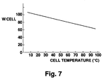
- Fig. 7 shows the relation between the temperature of solar cells and the power output by the cells (W/cell) in the case of monocrystalline silicon (Si) solar cells.
- the horizontal axis shows solar cell temperature
- the vertical axis shows power output of the cells (W/cell).
- the power generating capacity of the cells decreases as the cell temperature rises.
- the power generated when the cell temperature is 100°C is approx. 60% of the power generated at 25°C.
- the reason for this decrease is thought to be that as the temperature of the cells rises, molecular motion in the cell substrate material becomes more intense so that movement of holes and electrons, which are carriers of charge produced by an photoelectric effect, is impeded.
- the insulating material or the materials of which the solar cells are made may break down or expand, shortening cell lifetime.
- a solar module formed by arranging a plurality of solar cells on a cell stage is cooled by immersion in water using a jacket technique.
- a technique is also disclosed wherein a water cooling tube is installed on the underside of the module so that an electrode-inducing end does not become wet.
- Another cooling method is to install an air cooling fin on the underside of the module.
- the upper surface of the solar cells may be covered with a thin resin and the body cooled by air as it moves.
- no cooling device may be installed so as to avoid cost increases.
- a light converging type of solar cell has become popular wherein a converging lens is used to increase the amount of incident light falling on the cells and thereby permit reduction of their area. This shortens the number of energy recovery years or energy payback period (i.e., the number of years in which the energy used in manufacturing the module can be recovered as power output), and reduces the cost of a power generating system.
- energy recovery years or energy payback period i.e., the number of years in which the energy used in manufacturing the module can be recovered as power output
- temperature increases also become larger as converging power increases.
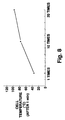
- Fig. 8 shows the relationship between power increase of the module converging lens and temperature rise of the solar cell.
- the horizontal axis shows converging power and the vertical axis shows cell temperature.
- the value of the cell temperature on the vertical axis of Fig. 8 is the temperature of the cell one minute after beginning exposure of the cell to solar irradiation without cooling.
- a converging power of 1 means that no converging effect is applied, the solar energy falling on the cell in this case being 0.1W/cm 2 .
- the solar energy supplied to the cell is 1W/cm 2
- the solar energy is 2W/cm 2 .
- This invention which was conceived in view of the above problems, therefore aims to provide a more effective method of cooling solar cells.
- a method of cooling solar cells wherein a light receiving surface of a cell is directly cooled by a coolant.
- an electrode is formed on a surface opposite to the light receiving surface of the solar cell according to the first aspect.
- a coolant is supplied as a pulsative flow to the light receiving surface of the solar cell according to the first aspect.
- the light receiving surface of the solar cell according to the third aspect has an inverted pyramid texture.
- the coolant is supplied as a jet spray to the light receiving surface of the solar cell according to the first aspect.
- the coolant absorbs light of longer wavelength than the wavelength of light corresponding to the band gap of the semiconductor material used to manufacture the solar cell according to the first aspect.
- the coolant according to the sixth aspect is either an aqueous solution of barium sulfate or an aqueous solution of NaCl.
- a method of direct cooling wherein a solar cell is disposed on one wall of a pipe of rectangular cross-section, a window of an optically transparent material for collecting sunlight is disposed on the opposite wall of the pipe facing the solar cell, and coolant is supplied via the pipe to the light receiving surface of the cell so that the surface is directly cooled, the distance between the surface and the optically transparent material being 0.5-2mm.
- the diameter of the pipe according to the eighth aspect is greater than the distance between the light receiving surface of the solar cell and the optically transparent material in parts other than the parts where the solar cell and window are formed.
- a thin film of Ag is formed on the surface of the optically transparent material in contact with the coolant according to the eighth aspect.
- a concave lens is used as the optically transparent material according to the eighth aspect.
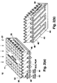
- Fig. 1 is a diagram in cross-section of a first embodiment of the method of cooling a solar cell according to this invention.
- Fig. 2(a) and 2(b) are views in perspective of a solar cell used in the first embodiment shown in Fig. 1.
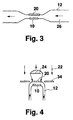
- Fig. 3 is a diagram showing one modification of a pipe according to the first embodiment shown in Fig. 1.
- Fig. 4 is a diagram showing another modification of the pipe according to the first embodiment shown in Fig. 1.
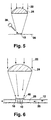
- Fig. 5 is a diagram in cross-section of a fourth embodiment of the method of cooling a solar cell according to this invention.
- Fig. 6 is a diagram in cross-section of a fifth embodiment of the method of cooling a solar cell according to this invention.
- Fig. 7 is a diagram showing a relation between the temperature of a solar cell and the power generating capacity of the cell.
- Fig. 8 is a diagram showing a relation between the converging power of a lens and the temperature of a solar cell.
- Fig. 1 shows a diagram in cross-section of a first embodiment of the method of cooling solar cells according to this invention.
- a solar cell 10 is disposed on a lower wall 14 of a pipe 12 with rectangular cross-section, and a window 18 for collecting sunlight is disposed on a upper wall 16 of a pipe 12 in a position facing the cell 10.
- a flat, optically transparent piece 20 such as a glass or transparent resin plate covers this window 18.
- a converging lens 24 is also fixed to a solar module, not shown, in order to converge sunlight 22 on a light receiving surface 11 of the cell 10 via the optically transparent piece 20. It will be understood that although only one of the cells 10 and one of the lenses 24 are shown for the sake of clarity, a solar module will in practice comprise a plurality of the cells 10 and lenses 24.
- a coolant 26 flows through the aforesaid pipe 12 so that the surfaces of each of the solar cells 10 are directly cooled by the coolant 26.
- the coolant 26 is usually water, but alcohol, acetone or flon, etc., may also be used according to the application.
- the focal length of this lens 24 should be small.
- a lens of small diameter and high curvature is therefore used. From the viewpoint of reducing light absorption by the lens 24, it is not however advantageous to increase the curvature of the lens 24 such that its thickness increases, hence it is desirable to reduce its diameter while retaining a similar contour and without changing the material and curvature.
- For a large lens and small lens of similar contour light is refracted by the same amount at corresponding positions on the lenses, so the focus approaches the lens by an amount depending on its reduction in size and consequently the focal length becomes shorter.
- a flat Fresnel lens or the like may also be used as the converging lens 24.
- the converging lens 24 may for example be a spherical lens of diameter 20-80 mm, or a 20-80 mm rectangular lens having the shape of a square, and their focal lengths may be of the order of 30-100 mm.
- the solar cell 10 shown in Fig. 1 should preferably be of a high efficiency crystalline silicon type, but chemical compound type solar cells such as GaAs, CdTe, CdS, CIS (CuInse) may also be used depending on the case.
- chemical compound type solar cells such as GaAs, CdTe, CdS, CIS (CuInse) may also be used depending on the case.
- the solar cell 10 When a direct coolant 26 is introduced on the light receiving surface 11 of the solar cell 10 as in the case of this embodiment and metal electrodes are on the surface 11, corrosion may occur and the cell will consequently be unable to withstand long periods of use.
- positive electrodes 42 and negative electrodes 44 are disposed on the underside of the cell 10 opposite to the light receiving surface 11 so that these electrodes do not come in direct contact with the coolant 26, as shown in Fig. 2(a) and (b).
- the cells may comprise monocrystalline silicon (Si) or polycrystalline silicon.
- a substrate 28 comprises p type Si, and the light receiving surface 11 of the substrate 28 has an inverted pyramid texture so as to fully absorb the sunlight 22.
- the rough texture formed on this substrate 28 is covered by a passivation film 30, this passivation film 30 being further covered by a reflection preventing film 32.
- the p type Si substrate 28 has an impurity concentration of the order of 10 15 -10 16 cm -3 to increase the lifetime of the carriers as much as possible, and its resistivity corresponds to 100-1000 ⁇ cm.
- n + layers 46 and p + layers 48 are formed alternately.
- Negative electrodes 44 are formed on the n + layers 46 and positive electrodes 42 are formed on the p + layers 48 respectively, the positive electrodes 42 being connected in parallel and the negative electrodes 44 being connected in parallel. In such a structure, carriers can be effectively withdrawn from the entire surface of the solar cell 10.
- the pipe 12 When flon or the like is used as the coolant, the temperature of the pipe 12 rises when it is irradiated by sunlight, and the liquid flon flowing through the pipe 12 may vaporize. If the flon in the pipe 12 vaporizes, the cooling effect of the solar cell 10 declines.
- the pipe 12 may be disposed in a vertical direction, i.e., in the same direction as the propagation direction of the sunlight 22 as shown in Fig. 4, only that part of the pipe adjoining the solar cell 10 being horizontal so as to fully absorb the sunlight 22. In such a case, the part of the pipe which is vertically disposed is shielded by a piece 34 so that sunlight does not shine on it. This prevents parts of the pipe 12 other than those where the solar cell 10 is formed from being irradiated by the sunlight, and prevents vaporization of flon coolant in the pipe 12.
- Table 1 shows a comparison of the cooling effect obtained by the solar cell cooling method according to this embodiment and that obtained by the prior art.
- the solar cell 10 used comprised monocrystalline Si having the rough texture shown in Fig. 2, and the coolant was water at 20°C. The convergence of the sunlight was 20 times in all cases.
- sunlight contains light which contributes, and light which does not contribute, to the photoelectric effect of the cell 10.
- the band gap is 1.1 eV, so only light of shorter wavelength than approx. 1120 nm can contribute to the photoelectric effect. If, therefore, light of longer wavelength which cannot contribute to the photoelectric effect of the cell 10 is absorbed by the coolant without irradiating the surface 11, and thereby removed outside the device, temperature rise of the solar cell 10 may be still further suppressed and cooling potential enhanced.
- a material is employed as coolant which absorbs light of longer wavelength than the wavelength corresponding to the band gap of the semiconductor material used.
- the coolant must not however absorb shorter wavelengths which contribute to the photoelectric effect of the solar cell 10, and must therefore have a selective absorption function.
- an aqueous solution of barium sulfate or an aqueous solution of NaCl are for example suitable.
- a thin Ag film of for example several 100 Angstroms thickness may be vapor deposited on the underside, i.e., the side in contact with the coolant, of the transparent piece 20 in Fig. 1.
- the operating temperature of the solar cell 10 in Table 1 may be lowered by 2 - 3°C compared to the case where water alone is used as coolant.
- Embodiment 1 the coolant was made to flow continuously, but if it is given a pulsative flow, the overall flowrate can be reduced and the power consumed by the pump is correspondingly reduced. Conversely, when the power consumed by the pump is the same, the peak flowrate for pulsative flow may be made larger than the flowrate for continuous flow.
- pulsative flow means a flow in which the flowrate varies.
- Table 2 gives a comparison of cooling effect for continuous flow and pulsative flow when the light receiving surface 11 of the solar cell 10 is a mirror surface and when it has a rough texture. It should be noted that the temperature shown in Table 2 is the temperature when the solar cell reached a steady state at a converging power of 50, and that the temperature of the cooling water used was 20°C. Various types of pulsative flowrate pattern may be envisaged, however in the experiment shown in Table 2, the peak flowrate of the pulsative flow is the same as that of continuous flow and the power consumed by the pump is approx. 1/2 - 4/5.
- the cooling effect is less than for a mirror surface, however when a pulsative flow is used the peak flowrate can be set high without increasing the power consumption of the pump so that the cell can be cooled to a sufficiently low temperature (38°C for a pump power consumption of 65W and a maximum flowrate of 30 cm/s).
- Fig. 5 shows a section of a fourth embodiment of the method of cooling a solar cell according to this invention.
- the solar cell 10 is mounted on a cell stage 36, and a coolant nozzle 38 is installed above the solar cell 10 at an oblique angle.
- a jet of coolant is sprayed continuously or intermittently by the cooling nozzle 38 so as to impinge on the solar cell 10.
- the spray amount of coolant used is for example of the order of 10 - 20 cc/cm 2 per minute.
- the solar cell may be cooled to 30°C or below when the sunlight 22 is converged by a power of 50, i.e., under the same conditions as those shown in Table 2.
- Table 3 shows a comparison of cooling effects and solar cell outputs according to the prior art and according to Embodiment 1 and Embodiment 4 of this invention.
- Table 3 shows the case when a water cooling pipe is disposed adjacent to the underside of the solar module so as to cool the cell indirectly as an example of the prior art, the case where the solar cell 10 is cooled by the method shown in Fig. 5 as an example of Embodiment 4, and the case where the solar cell 10 is cooled by the method of Fig. 1 as an example of Embodiment 1.
- a rough texture is formed on the light receiving surface 11, and the values given for cell temperature and cell output both correspond to the case when the sunlight is converged by a power of 50.
- the running temperature of the cell may be reduced to a minimum of 27°C even when the solar cell 10 having the Table 3 CONVERGING POWER OF 50 COOLING METHOD POWER CONSUMPTION OF WATER COOLING PUMP (w/cell) CELL TEMPERATURE CELL OUTPUT TOTAL OUTPUT PRIOR ART EXAMPLE INDIRECT COOLING OF MODULE UNDERSIDE BY WATER COOLING PIPE 0.1 w/cell 140°C ⁇ 170°C 0.3 ⁇ 0.4 w/cell 0.2 ⁇ 0.3 w/cell EMBODIMENT 4 Fig.
- Embodiment 1 0.1 w/cell 36°C 0.76 w/cell 0.66 w/cell light receiving surface 11 with a rough texture is used.
- the cell output may be greatly increased in both cases compared to the prior art.
- the total output of the solar cell which is obtained by subtracting the power consumption of the pump from the cell output may be largely increased in both Embodiment 1 and Embodiment 4 as compared to the prior art, and the power generating efficiency per cell may be remarkably improved.
- the flowrate of coolant used is greatly reduced, therefore the power consumption of the pump can be greatly reduced by a corresponding amount and the power generating efficiency per cell may be increased.
- the transparent piece of glass 20 or similar material is unnecessary, so there is also no attenuation of sunlight due to this piece 20.
- Fig. 6 is a view in section of a fifth embodiment of the method of cooling a solar cell according to this invention.
- a concave lens 40 is installed instead of the plate-shaped optically transparent piece in the window 18 formed in the pipe 12.
- the sunlight 22 converged by the converging lens 24 is converted by the concave lens 40 to a parallel beam which is perpendicular to the light receiving surface 11 of the solar cell 10, and irradiates the light receiving surface 11 of the cell 10 with a uniform light intensity. This renders the generated carrier distribution inside the solar cell 10 more uniform and renders the potential distribution set up in the cell 10 more uniform, so the power output obtained is increased.
- Table 4 shows a comparison of the total output per solar cell, i.e. the value obtained by subtracting the power consumption of the pump from the power generated by the solar cell 10, in the case of Embodiment 1 and Embodiment 5.
- the light receiving surface of the solar cell can be directly cooled by the coolant, hence the temperature of the cell can be efficiently and effectively decreased.
- the power generating efficiency of the cell is improved, and the lifetime of the cell is lengthened.
- Electrodes of the solar cell are formed on the underside of the cell opposite to the light receiving surface, corrosion of the electrodes may be avoided even when Table 4 CELL TEMPERATURE TOTAL OUTPUT EMBODIMENT 1 36°C 0.66 w/cell EMBODIMENT 5 37°C 0.69 ⁇ 0.71 w/cell the light receiving surface is directly cooled.
- the cooling effect may be enhanced.
- the cell By jet spraying the coolant which cools the solar cell, the cell may be effectively cooled even when only a small amount of coolant is used.
- the band gap is 1.1 eV, only light which is of shorter wavelength than approx. 1120 nm contributes to the photoelectric effect, and light of longer wavelength is absorbed by the coolant so temperature rise of the solar cell may be further suppressed.
Landscapes
- Photovoltaic Devices (AREA)
- Cooling Or The Like Of Semiconductors Or Solid State Devices (AREA)
Applications Claiming Priority (2)
| Application Number | Priority Date | Filing Date | Title |
|---|---|---|---|
| JP8021369A JPH09213980A (ja) | 1996-02-07 | 1996-02-07 | 太陽電池の冷却方法 |
| JP21369/96 | 1996-02-07 |
Publications (2)
| Publication Number | Publication Date |
|---|---|
| EP0789405A2 true EP0789405A2 (de) | 1997-08-13 |
| EP0789405A3 EP0789405A3 (de) | 1998-12-30 |
Family
ID=12053190
Family Applications (1)
| Application Number | Title | Priority Date | Filing Date |
|---|---|---|---|
| EP97100553A Withdrawn EP0789405A3 (de) | 1996-02-07 | 1997-01-15 | Verfahren zum Abkühlen von Sonnenzellen |
Country Status (2)
| Country | Link |
|---|---|
| EP (1) | EP0789405A3 (de) |
| JP (1) | JPH09213980A (de) |
Cited By (15)
| Publication number | Priority date | Publication date | Assignee | Title |
|---|---|---|---|---|
| NL1006838C2 (nl) * | 1997-08-25 | 1999-03-04 | Univ Eindhoven Tech | Paneelvormige hybride fotovoltaïsche/thermische inrichting. |
| WO2000008690A3 (de) * | 1998-08-05 | 2000-05-11 | Windbaum Forschungs Und Entwic | Photovoltaikeinrichtung |
| NL1010787C2 (nl) * | 1998-12-11 | 2000-06-19 | Stichting Energie | Vloeistofhoudende zonnecel en daarmee samengesteld zonnepaneel. |
| EP0984494A4 (de) * | 1998-03-19 | 2001-05-09 | Toyota Motor Co Ltd | Solarzellenbatterie |
| WO2002080286A1 (en) * | 2001-03-28 | 2002-10-10 | Solar Systems Pty Ltd | Cooling circuit for receiver of solar radiation |
| WO2003107440A3 (en) * | 2002-06-13 | 2004-08-05 | Enfis Ltd | Opteolectronic devices |
| US6806415B2 (en) | 2000-11-10 | 2004-10-19 | Canon Kabushiki Kaisha | Method for controlling a solar power generation system having a cooling mechanism |
| US7109461B2 (en) | 2001-03-28 | 2006-09-19 | Solar Systems Pty Ltd. | Solar tracking system |
| AU2002244519B2 (en) * | 2001-03-28 | 2007-11-15 | Solar Systems Pty Ltd | Cooling circuit for receiver of solar radiation |
| US7550054B2 (en) | 2001-03-28 | 2009-06-23 | Solar Systems Pty Ltd. | Method of manufacturing mirrors for a dish reflector |
| WO2011110896A1 (en) * | 2010-03-08 | 2011-09-15 | Sunlego Enerji Sistemleri Sanayi Ve Ticaret Anonim Sirketi | System for integrated solar energy conversion |
| US8049097B2 (en) | 2008-08-11 | 2011-11-01 | General Electric Company | Solar cell including cooling channels and method for fabrication |
| EP2608278A1 (de) * | 2011-12-21 | 2013-06-26 | Industrial Technology Research Institute | Solarzellenmodul |
| WO2013071315A3 (en) * | 2011-11-12 | 2014-02-20 | Samuels Davian A | Solar energy collectors and methods for capturing solar energy |
| ITMI20131937A1 (it) * | 2013-11-21 | 2015-05-22 | Er En | Pannello fotovoltaico |
Families Citing this family (12)
| Publication number | Priority date | Publication date | Assignee | Title |
|---|---|---|---|---|
| JP4953745B2 (ja) * | 2006-09-26 | 2012-06-13 | シャープ株式会社 | 集光型太陽光発電ユニットおよび集光型太陽光発電装置 |
| JP4693793B2 (ja) * | 2007-01-31 | 2011-06-01 | シャープ株式会社 | 太陽電池、集光型太陽光発電モジュール、集光型太陽光発電ユニット、および太陽電池製造方法 |
| US8513514B2 (en) | 2008-10-24 | 2013-08-20 | Suncore Photovoltaics, Inc. | Solar tracking for terrestrial solar arrays with variable start and stop positions |
| KR100974016B1 (ko) * | 2008-03-17 | 2010-08-05 | 주식회사 티지솔라 | 씨스루형 태양전지 |
| JP2010034108A (ja) | 2008-07-25 | 2010-02-12 | Daido Gakuen | 太陽電池パネルの冷却装置および冷却方法 |
| US8507837B2 (en) | 2008-10-24 | 2013-08-13 | Suncore Photovoltaics, Inc. | Techniques for monitoring solar array performance and applications thereof |
| JP2011009733A (ja) * | 2009-05-28 | 2011-01-13 | Kyocera Corp | 太陽電池素子、太陽電池モジュールおよび太陽光発電装置 |
| JP2011222824A (ja) * | 2010-04-12 | 2011-11-04 | Lden Co Ltd | 太陽電池モジュールの排熱回収方法とその排熱回収装置 |
| JP2013207079A (ja) * | 2012-03-28 | 2013-10-07 | Sumitomo Electric Ind Ltd | 集光型太陽光発電パネル及び集光型太陽光発電装置 |
| KR101273998B1 (ko) * | 2012-10-22 | 2013-06-12 | 주식회사 쏠틱스 | 집광식 태양광발전장치 및 이를 이용한 태양광발전시스템 |
| KR101571926B1 (ko) * | 2013-06-25 | 2015-12-07 | 김미애 | 평면거울들을 이용하여 균일하게 집광된 광빔 및 직접 접촉에 의한 냉각법을 이용한 태양광발전 장치 및 방법 |
| JP6292266B2 (ja) * | 2016-09-07 | 2018-03-14 | 住友電気工業株式会社 | 集光型太陽光発電パネル及び集光型太陽光発電装置 |
Citations (1)
| Publication number | Priority date | Publication date | Assignee | Title |
|---|---|---|---|---|
| JPH0583881A (ja) | 1991-09-19 | 1993-04-02 | Hitachi Ltd | 太陽エネルギ利用システム |
Family Cites Families (6)
| Publication number | Priority date | Publication date | Assignee | Title |
|---|---|---|---|---|
| US4045246A (en) * | 1975-08-11 | 1977-08-30 | Mobil Tyco Solar Energy Corporation | Solar cells with concentrators |
| US4191594A (en) * | 1976-07-09 | 1980-03-04 | Virgil Stark | Solar energy conversion |
| US4052228A (en) * | 1976-07-12 | 1977-10-04 | Russell Charles R | Optical concentrator and cooling system for photovoltaic cells |
| US4146407A (en) * | 1977-12-15 | 1979-03-27 | Litsenko Tatyana A | Solar photoelectric module |
| US4135537A (en) * | 1978-03-20 | 1979-01-23 | Atlantic Richfield Company | Light collector |
| FR2475297A1 (fr) * | 1980-02-01 | 1981-08-07 | Silicium Semiconducteur Ssc | Procede de refroidissement d'une cellule solaire et dispositif solaire mixte photovoltaique et photothermique |
-
1996
- 1996-02-07 JP JP8021369A patent/JPH09213980A/ja active Pending
-
1997
- 1997-01-15 EP EP97100553A patent/EP0789405A3/de not_active Withdrawn
Patent Citations (1)
| Publication number | Priority date | Publication date | Assignee | Title |
|---|---|---|---|---|
| JPH0583881A (ja) | 1991-09-19 | 1993-04-02 | Hitachi Ltd | 太陽エネルギ利用システム |
Cited By (24)
| Publication number | Priority date | Publication date | Assignee | Title |
|---|---|---|---|---|
| NL1006838C2 (nl) * | 1997-08-25 | 1999-03-04 | Univ Eindhoven Tech | Paneelvormige hybride fotovoltaïsche/thermische inrichting. |
| WO1999010934A1 (en) * | 1997-08-25 | 1999-03-04 | Technische Universiteit Eindhoven | A panel-shaped, hybrid photovoltaic/thermal device |
| EP0984494A4 (de) * | 1998-03-19 | 2001-05-09 | Toyota Motor Co Ltd | Solarzellenbatterie |
| WO2000008690A3 (de) * | 1998-08-05 | 2000-05-11 | Windbaum Forschungs Und Entwic | Photovoltaikeinrichtung |
| US6407328B2 (en) | 1998-08-05 | 2002-06-18 | Powerpulse Holding Ag | Photovoltaic device |
| CN100385687C (zh) * | 1998-08-05 | 2008-04-30 | 电力脉冲控股有限公司 | 光生伏打装置 |
| NL1010787C2 (nl) * | 1998-12-11 | 2000-06-19 | Stichting Energie | Vloeistofhoudende zonnecel en daarmee samengesteld zonnepaneel. |
| WO2000036618A1 (en) * | 1998-12-11 | 2000-06-22 | Stichting Energieonderzoek Centrum Nederland | Liquid-containing solar cell and solar panel assembled therewith |
| AU766126B2 (en) * | 1998-12-11 | 2003-10-09 | Stichting Energieonderzoek Centrum Nederland | Solar cell and solar panel assembled therewith |
| US7754963B2 (en) | 2000-11-10 | 2010-07-13 | Canon Kabushiki Kaisha | Solar power generation system having cooling mechanism |
| US6806415B2 (en) | 2000-11-10 | 2004-10-19 | Canon Kabushiki Kaisha | Method for controlling a solar power generation system having a cooling mechanism |
| US7109461B2 (en) | 2001-03-28 | 2006-09-19 | Solar Systems Pty Ltd. | Solar tracking system |
| US7076965B2 (en) | 2001-03-28 | 2006-07-18 | John Beavis Lasich | Cooling circuit for receiver of solar radiation |
| AU2002244519B2 (en) * | 2001-03-28 | 2007-11-15 | Solar Systems Pty Ltd | Cooling circuit for receiver of solar radiation |
| US7550054B2 (en) | 2001-03-28 | 2009-06-23 | Solar Systems Pty Ltd. | Method of manufacturing mirrors for a dish reflector |
| WO2002080286A1 (en) * | 2001-03-28 | 2002-10-10 | Solar Systems Pty Ltd | Cooling circuit for receiver of solar radiation |
| WO2003107440A3 (en) * | 2002-06-13 | 2004-08-05 | Enfis Ltd | Opteolectronic devices |
| US8049097B2 (en) | 2008-08-11 | 2011-11-01 | General Electric Company | Solar cell including cooling channels and method for fabrication |
| WO2011110896A1 (en) * | 2010-03-08 | 2011-09-15 | Sunlego Enerji Sistemleri Sanayi Ve Ticaret Anonim Sirketi | System for integrated solar energy conversion |
| WO2013071315A3 (en) * | 2011-11-12 | 2014-02-20 | Samuels Davian A | Solar energy collectors and methods for capturing solar energy |
| EP2608278A1 (de) * | 2011-12-21 | 2013-06-26 | Industrial Technology Research Institute | Solarzellenmodul |
| CN103178146A (zh) * | 2011-12-21 | 2013-06-26 | 财团法人工业技术研究院 | 太阳能电池模块 |
| ITMI20131937A1 (it) * | 2013-11-21 | 2015-05-22 | Er En | Pannello fotovoltaico |
| WO2015075625A1 (en) * | 2013-11-21 | 2015-05-28 | Fondazione Centro Internazionale Della Fotonica Per Energia | Photovoltaic panel |
Also Published As
| Publication number | Publication date |
|---|---|
| EP0789405A3 (de) | 1998-12-30 |
| JPH09213980A (ja) | 1997-08-15 |
Similar Documents
| Publication | Publication Date | Title |
|---|---|---|
| EP0789405A2 (de) | Verfahren zum Abkühlen von Sonnenzellen | |
| US5482568A (en) | Micro mirror photovoltaic cells | |
| US20080302357A1 (en) | Solar photovoltaic collector hybrid | |
| TWI487127B (zh) | 太陽能電池模組 | |
| US20120097216A1 (en) | Hybrid solar receiver and concentrating solar system comprising the same | |
| JP2013520785A (ja) | 集中型太陽光発電及び熱システム | |
| CN102113135A (zh) | 用于抛物面太阳能反射器的球面成像透镜的光伏发电机 | |
| US9157657B2 (en) | Method of cooling a solar concentrator | |
| KR101981447B1 (ko) | 태양광 발전장치 | |
| US11094840B2 (en) | Photovoltaic system with non-uniformly cooled photovoltaic cells | |
| EP0573557A4 (en) | Solar energy system | |
| KR101237306B1 (ko) | 태양에너지 변환장치에 적용되는 광전지 모듈 냉각장치 | |
| KR20120056648A (ko) | 태양전지와 열전소자를 이용한 온수 가열 기능을 갖는 발전 시스템 | |
| KR100755505B1 (ko) | 태양전지-태양열에너지 병합장치 | |
| CN115001359A (zh) | 一种基于太阳能分频的光伏光热联合发电装置 | |
| US12476587B2 (en) | Hybrid solar panel | |
| KR102625589B1 (ko) | 파사드형 bipvt 모듈 및 그의 제조방법 | |
| JPS595807B2 (ja) | ハイブリッド型太陽熱コレクタ | |
| KR101327211B1 (ko) | 고집광형 태양전지모듈 | |
| WO2019178678A1 (en) | Photovoltaic microcell array with multi-stage concentrating optics | |
| KR101220096B1 (ko) | 태양에너지를 활용한 에너지 변환장치 | |
| US20240162847A1 (en) | Hybrid solar panel | |
| KR101132567B1 (ko) | 태양광 집광 장치 | |
| JP3968422B2 (ja) | 太陽光ハイブリッドモジュール | |
| CN118508868A (zh) | 一种液体光漏斗反射高效液冷双面光伏电池发电玻璃管 |
Legal Events
| Date | Code | Title | Description |
|---|---|---|---|
| PUAI | Public reference made under article 153(3) epc to a published international application that has entered the european phase |
Free format text: ORIGINAL CODE: 0009012 |
|
| 17P | Request for examination filed |
Effective date: 19970212 |
|
| AK | Designated contracting states |
Kind code of ref document: A2 Designated state(s): DE GB IT |
|
| RIN1 | Information on inventor provided before grant (corrected) |
Inventor name: OKAWA, SUSUMU Inventor name: TANGE, KYOICHI |
|
| PUAL | Search report despatched |
Free format text: ORIGINAL CODE: 0009013 |
|
| AK | Designated contracting states |
Kind code of ref document: A3 Designated state(s): DE GB IT |
|
| STAA | Information on the status of an ep patent application or granted ep patent |
Free format text: STATUS: THE APPLICATION IS DEEMED TO BE WITHDRAWN |
|
| 18D | Application deemed to be withdrawn |
Effective date: 20000801 |