EP0789339B1 - Securing element for the electronic protection of articles - Google Patents
Securing element for the electronic protection of articles Download PDFInfo
- Publication number
- EP0789339B1 EP0789339B1 EP97100487A EP97100487A EP0789339B1 EP 0789339 B1 EP0789339 B1 EP 0789339B1 EP 97100487 A EP97100487 A EP 97100487A EP 97100487 A EP97100487 A EP 97100487A EP 0789339 B1 EP0789339 B1 EP 0789339B1
- Authority
- EP
- European Patent Office
- Prior art keywords
- magnetic material
- soft magnetic
- security element
- layers
- radius
- Prior art date
- Legal status (The legal status is an assumption and is not a legal conclusion. Google has not performed a legal analysis and makes no representation as to the accuracy of the status listed.)
- Expired - Lifetime
Links
Images


Classifications
-
- G—PHYSICS
- G08—SIGNALLING
- G08B—SIGNALLING OR CALLING SYSTEMS; ORDER TELEGRAPHS; ALARM SYSTEMS
- G08B13/00—Burglar, theft or intruder alarms
- G08B13/22—Electrical actuation
- G08B13/24—Electrical actuation by interference with electromagnetic field distribution
- G08B13/2402—Electronic Article Surveillance [EAS], i.e. systems using tags for detecting removal of a tagged item from a secure area, e.g. tags for detecting shoplifting
- G08B13/2405—Electronic Article Surveillance [EAS], i.e. systems using tags for detecting removal of a tagged item from a secure area, e.g. tags for detecting shoplifting characterised by the tag technology used
- G08B13/2408—Electronic Article Surveillance [EAS], i.e. systems using tags for detecting removal of a tagged item from a secure area, e.g. tags for detecting shoplifting characterised by the tag technology used using ferromagnetic tags
-
- G—PHYSICS
- G08—SIGNALLING
- G08B—SIGNALLING OR CALLING SYSTEMS; ORDER TELEGRAPHS; ALARM SYSTEMS
- G08B13/00—Burglar, theft or intruder alarms
- G08B13/22—Electrical actuation
- G08B13/24—Electrical actuation by interference with electromagnetic field distribution
- G08B13/2402—Electronic Article Surveillance [EAS], i.e. systems using tags for detecting removal of a tagged item from a secure area, e.g. tags for detecting shoplifting
- G08B13/2428—Tag details
- G08B13/2434—Tag housing and attachment details
-
- G—PHYSICS
- G08—SIGNALLING
- G08B—SIGNALLING OR CALLING SYSTEMS; ORDER TELEGRAPHS; ALARM SYSTEMS
- G08B13/00—Burglar, theft or intruder alarms
- G08B13/22—Electrical actuation
- G08B13/24—Electrical actuation by interference with electromagnetic field distribution
- G08B13/2402—Electronic Article Surveillance [EAS], i.e. systems using tags for detecting removal of a tagged item from a secure area, e.g. tags for detecting shoplifting
- G08B13/2428—Tag details
- G08B13/2437—Tag layered structure, processes for making layered tags
- G08B13/2442—Tag materials and material properties thereof, e.g. magnetic material details
Definitions
- the invention relates to a securing element in the preamble of Claim 1 specified Art.
- Elements of the aforementioned type are preferably in Electronic goods surveillance in department stores and bearings used.
- a particularly advantageous embodiment such an element is from DE 42 42nd 992 A1 became known.
- So-called "thin film” labels to secure preferably CDs described consist of a thin, in the ⁇ m range lying layer of soft magnetic material. The layer is e.g. by means of a physical deposition process onto a carrier substrate under vacuum conditions applied.
- Thin film labels show an anisotropic structure.
- Anisotropic means that the soft magnetic layer is made of of which the "thin film” labels are formed, one Preferred axis.
- the anisotropic structure makes itself felt In practice, this is noticeable in that the "Thin Film” label in response to a query field characteristic signal is maximum if query field and Preferred axis are aligned parallel to each other; the However, the signal disappears if the preferred axis and Query field are perpendicular to each other.
- EP 123 586 B proposes in addition to two query fields with frequencies f1 and f2 in the kHz range a field with one in the Hz range frequency in the query zone.
- the low frequency Query field causes the fuse element in the Clock of this field from saturation in one direction to Saturation is driven in the other direction.
- the characteristic signal therefore occurs periodically with the Frequency of the low-frequency field.
- An alternative solution has also become known, merely a query field in the kHz range to excite the Use security element, the characteristic signal of the fuse element in turn in time with a low-frequency field, which is the soft magnetic Material between the two saturations drifts, occurs.
- EP-A 0 567 080 is a securing element in the preamble of the claim 1 specified type known. It is an annular securing element, which in an annular groove provided in an optical information storage disc is glued in then closed by a coating covering the surface of the plate. The width of the annular securing element is reduced in at least two places, which are spaced about ninety degrees apart by at least two narrow switching ranges to form, which alternate with wide river collection areas. The overall orthogonal Relative orientation of the switching ranges ensures multidirectional detection of the fuse element in a query field.
- the invention is based, one out of a task securing element not simply connected surface to create its detection rate is comparable to the detection rate of a security element, that from a simply connected surface consists.
- the change is made in such a way that the given characteristic signal reduced to a pronounced peak is.
- the soft magnetic material from these areas completely or at least partially removed, that becomes characteristic Signal to a pronounced peak (or two symmetrically lying peaks) reduced.
- the soft magnetic is proposed Material along the legs of a triangular Area as well as in strip-shaped sections that parallel to one placed on the inner radius and the Base side of the triangle forming tangent are arranged, to remove. Removing the soft magnetic material from the desired areas, for example, by mechanical processing or by steaming away (e.g. by means of Laser).
- this is characteristic signal maximum when exciting magnetic field and preferred axis are parallel to each other; with vertical Position it disappears.
- the securing element from at least two layers of soft magnetic Material exists, with the preferred axes of the Were preferably at an angle of 360 ° / (2 • n) relative are turned towards each other; n denotes the in the formula Number of layers.
- Two layers are a concrete example of soft magnetic material called with their Preferred axes are perpendicular to each other.
- a semi-hard or hard magnetic material is usually arranged on or near the soft magnetic material.
- This so-called deactivator material is characterized by a high coercive force and a relatively low permeability. If the deactivator material is exposed to such a strong magnetic field that it is driven into saturation, it subsequently prevents the reaction of the soft magnetic material to the magnetic field in the interrogation zone.
- a layer of semi-hard or hard magnetic material is provided at least between two of the layers of the soft magnetic material.
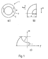
- Fig. 1a shows an electronic fuse element 1, the has the shape of a ring 5.
- a security element 1 is already known from DE 42 52 992 A1 become.
- the soft magnetic material 3 of the securing element 1 has an anisotropic structure a preferred axis XV is marked. For reasons of symmetry it suffices the ring section shown in Fig. 1b viewed from 90 °.
- the ring 5 has one inner radius r and an outer radius R.
- Fig. 1c is the reciprocal Demagnetization factor 1 / N over the radius ⁇ of the in Fig. 1b shown ring section.
- the reciprocal Demagnetization factor N is a first approximation proportional to the length of the securing element 1 in Direction of the external magnetic field hext.
- the magnetization curve shows a very pronounced plateau P, the can be interpreted to mean that a relative large volume fraction V of the ring 5 is almost constant Demagnetization factor N has. This means that a relatively large volume fraction V of the ring 5 at almost same strength of the external magnetic field hext is demagnetized.
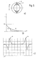
- the reaction of the ring-shaped Securing element 1 on an external magnetic field is hext from the figures Fig. 2a to Fig. 2d can be seen.
- FIG. 2a shows a simplified illustration of a soft magnetic material 3 with different demagnetization factors N1, N2 in different volume ranges V1, V2.
- the arrow indicates the preferred axis XV of the soft magnetic material 3.
- the hysteresis curves assigned to the volume regions V1, V2 with different demagnetization factors N1, N2 can be seen in FIG. 2b.
- the fuse element 1 is excited in the non-linear regions of the hysteresis curves (-> transition between the linear and the saturated region) to emit a signal A (t). If the hysteresis curves are traversed at a constant rate in time, the two volume ranges V1, V2 contribute their contributions to the characteristic signal A (t) at different times.
- FIG. 2c A breakdown according to individual signals can be seen in FIG. 2c.
- FIG. 3a shows a section of an embodiment of the securing element 1 according to the invention, which are particularly good for Securing CDs is suitable.
- a designed securing element around the central opening of the Placed on CD there are no imbalances affecting the playback result influence negatively.
- This will be advantageous soft magnetic material by means of a deposition process manufactured under vacuum conditions. It goes without saying it is also possible to produce the material layers by punching them out.
- the securing element 1 has the shape of a ring 5 with the inner radius r and the outer radius R.
- the selected area 2 is not a soft magnetic material 3 to find: either the invention Securing elements 1 already with the broken one Ring shape or the soft magnetic material 2 is subsequently replaced by mechanical or chemical Treatment of the corresponding areas 2 removed.
- the configuration is to be regarded as particularly advantageous if that the selected areas 2 fold symmetrically with respect the preferred axis XV of the soft magnetic material 3.
- the selected areas are approximate the shape of an isosceles triangle, the base of which from a section of the inner ring radius (r) is formed and its opposite the base side Tip lies on the outer radius (R). This is explained in more detail with reference to FIG. 5.
- FIG. 3b shows the course of the reciprocal demagnetization factor 1 / N over the radius ⁇ of the ring section shown in Fig. 3a.
- Fig. 1c shows the No plateau curve here. It works particularly well different behavior of the known and the annular securing element 1 according to the invention in the Recognize diagram, which is plotted in Fig. 4.
- Fig. 4 is the magnetized volume fraction of the in Fig. 1b and in Fig. 3a shown security element 1 depending on the outer magnetic field hext plotted. While the familiar Securing element 1 a pronounced, unfavorable plateau has the corresponding embodiment of the Securing element 1 according to the invention a smooth Course.
- this also shows the characteristic Signal A (t) of the fuse element 1 according to the invention only one of these is provided by the detector device articles in the query zone that are not allowed assigned - a pronounced peak (or two symmetrical peaks, symmetrical by the two lying non-linear areas of the hysteresis curve derived).
- FIG. 5a shows a further embodiment of the invention Fuse element 1.
- Fuse element 1 it is soft magnetic material 3 not entirely, but only from certain sections of the selected areas 2 removed Service.
- a triangular shape has proven to be particularly favorable of the selected area 2, the Triangle symmetrical with respect to the preferred axis XV is arranged.
- the soft magnetic material 3 is in Area of the legs of the triangular area 2 and in striped sections removed parallel to a tangent to the inner circle, where the tangent forms the base of the triangle.
- FIG. 5b A diagram representation analogous to FIG. 4 for this Embodiment of the securing element 1 according to the invention can be seen in Fig. 5b.
- the invention shows Securing element 1 the desired smooth course without plateau.
- the characteristic signal A (t) of the Securing element 1 only the two occur symmetrically lying peaks 4 (Fig. 5c).
- the characteristic signal A (t) of an anisotropically applied soft magnetic material 3 is maximum if its Preferred axis XV is parallel to the external magnetic field Hext.
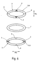
- FIG Securing element 1 two layers 6 of soft magnetic material 3 with its preferred axes XV approximately crossed over one another.
- This Overlay can be applied to any number of layers 6 expand, the optimal relative angular position of the 6 were to each other using the formula 360 ° / 2 • n (n indicates the number of layers 6) can be determined.
- n indicates the number of layers 6
- the in Fig. 6 illustrated embodiment is between the two Layers 6 of soft magnetic material 3 also one Layer 6 made of semi-hard or hard magnetic material 7 intended. This material 7 becomes saturated driven, the fuse element 1 is deactivated.
- the layers 6 of the soft magnetic material 3 in the two areas perpendicular to the selected ones Regions 2 each have a scratch 9 of length R-r. It has it turned out that the strength of the characteristic Signal A (t) of a ring 5 made of soft magnetic material 3 decreases from a certain size. This negative effect can by mechanical or chemical removal of the soft magnetic material 3 (e.g. by a scratch 9) in the area of the greatest linear expansion of the Remove securing element 1.
Abstract
Description
Die Erfindung betrifft ein Sicherungselement der im Oberbegriff des
Patentanspruchs 1 angegebenen Art.The invention relates to a securing element in the preamble of
Elemente der vorgenannten Art werden vorzugsweise im Bereich der elektronischen Warensicherung in Kaufhäusern und Lagern eingesetzt. Eine besonders vorteilhafte Ausgestaltung eines derartigen Elementes ist aus der DE 42 42 992 A1 bekannt geworden. In dieser Offenlegungsschrift sind sog. "Thin Film" Etiketten zur Sicherung von vorzugsweise CDs beschrieben. Sie bestehen aus einer dünnen, im µm-Bereich liegenden Schicht aus weichmagnetischem Material. Die Schicht wird z.B. mittels eines physikalischen Abscheideverfahrens unter Vakuumbedingungen auf ein Trägersubstrat aufgebracht.Elements of the aforementioned type are preferably in Electronic goods surveillance in department stores and bearings used. A particularly advantageous embodiment such an element is from DE 42 42nd 992 A1 became known. Are in this disclosure So-called "thin film" labels to secure preferably CDs described. They consist of a thin, in the µm range lying layer of soft magnetic material. The layer is e.g. by means of a physical deposition process onto a carrier substrate under vacuum conditions applied.
"Thin Film"-Etiketten zeigen einen anisotropen Aufbau. Anisotrop bedeutet, daß die weichmagnetische Schicht, aus der die "Thin Film"-Etiketten gebildet sind, eine Vorzugsachse besitzt. Der anisotrope Aufbau macht sich in der Praxis dadurch bemerkbar, daß das von dem "Thin Film"-Etikett als Antwort auf ein Abfragefeld remittierte charakteristische Signal maximal ist, wenn Abfragefeld und Vorzugsachse parallel zueinander ausgerichtet sind; das Signal verschwindet hingegen, wenn Vorzugsachse und Abfragefeld senkrecht zueinander stehen."Thin film" labels show an anisotropic structure. Anisotropic means that the soft magnetic layer is made of of which the "thin film" labels are formed, one Preferred axis. The anisotropic structure makes itself felt In practice, this is noticeable in that the "Thin Film" label in response to a query field characteristic signal is maximum if query field and Preferred axis are aligned parallel to each other; the However, the signal disappears if the preferred axis and Query field are perpendicular to each other.
Zur Detektierung von Sicherungselementen in einer Abfragezone sind eine Vielzahl unterschiedlicher Verfahren bekannt geworden. So wird in der EP 123 586 B vorgeschlagen, zusätzlich zu zwei Abfragefeldern mit den Frequenzen f1 und f2 im kHz-Bereich ein Feld mit einer im Hz-Bereich liegenden Frequenz in die Abfragezone zu senden. Die beiden Abfragefelder mit den Frequenzen f1 und f2 regen ein in der Abfragezone befindliches Sicherungselement zur Aussendung eines charakteristischen Signals mit den Intermodulationsfrequenzen n•f1 ± m•f2 (n, m = 0, 1, 2,...) an. Das niederfrequente Abfragefeld bewirkt, daß das Sicherungselement im Takt dieses Feldes von der Sättigung in eine Richtung zur Sättigung in die andere Richtung getrieben wird. Das charakteristische Signal tritt daher periodisch mit der Frequenz des niederfrequenten Feldes auf. Als alternative Lösung ist auch bekannt geworden, lediglich ein im kHz-Bereich liegendes Abfragefeld zur Erregung des Sicherungselementes zu verwenden, wobei das charakteristische Signal des Sicherungselementes wiederum im Takte eines niederfrequenten Feldes, das das weichmagnetische Material zwischen den beiden Sättigungen hinund hertreibt, auftritt.For the detection of security elements in an interrogation zone a variety of different methods are known become. For example, EP 123 586 B proposes in addition to two query fields with frequencies f1 and f2 in the kHz range a field with one in the Hz range frequency in the query zone. The two Query fields with the frequencies f1 and f2 stimulate in the Interrogation zone security element for transmission a characteristic signal with the intermodulation frequencies n • f1 ± m • f2 (n, m = 0, 1, 2, ...). The low frequency Query field causes the fuse element in the Clock of this field from saturation in one direction to Saturation is driven in the other direction. The characteristic signal therefore occurs periodically with the Frequency of the low-frequency field. An alternative solution has also become known, merely a query field in the kHz range to excite the Use security element, the characteristic signal of the fuse element in turn in time with a low-frequency field, which is the soft magnetic Material between the two saturations drifts, occurs.
Zwecks Auswertung wird die Form des charakteristischen Signals anschließend mit einer vorgegebenen Signalform verglichen. Stimmen beide überein, wird dies als unerlaubter Aufenthalt eines gesicherten Artikels in der Überwachungszone interpretiert; ein Alarm zeigt dem Bedienpersonal den Diebstahl an. For the purpose of evaluation, the shape of the characteristic Then signal with a predetermined waveform compared. If the two match, this is called unauthorized stay of a secured article in the Surveillance zone interpreted; an alarm shows that Operating theft.
Es hat sich in der Praxis gezeigt, daß bei Sicherungselementen, die nicht aus einer einfach zusammenhängenden Fläche bestehen, die Detektionsrate nicht den hohen an sie gestellten Anforderungen entspricht. Als Beispiel für ein derartiges Sicherungselement sei der in der DE 42 42 992 A1 beschriebene CD-Ring genannt. Dies liegt - wie im Zusammenhang mit den Figuren Fig. 1a bis Fig. 1d näher erläutert wird - daran, daß bei derartigen Sicherungselementen unterschiedliche Bereiche, denen quasi unterschiedliche Entmagnetisierungsfaktoren zuzuordnen sind, Einzelbeiträge zum charakteristischen Signal liefern. Der Entmagnetisierungsfaktor ist definiert als die inverse Steigung der Magnetisierungskurve. Infolge der unterschiedlichen Entmagnetisierungsfaktoren treten die Signale der einzelnen Bereiche zeitlich versetzt zueinander auf. Da die Auswerteeinrichtung nur ein charakteristisches Signal mit einem ausgeprägten Peak als von einem Sicherungselement herrührend erkennt, kann z.B. ein mit einem ringförmigen Sicherungselement versehener Artikel die Überwachungszone ungehindert passieren.It has been shown in practice that with securing elements, which are not from a simply coherent Area exist, the detection rate is not the high at it requirements. As an example of a such a securing element is that in DE 42 42 992 A1 described CD-Ring called. This is - as in the context with the figures Fig. 1a to Fig. 1d explained in more detail will - remember that with such security elements different Areas that are quasi different Demagnetization factors can be assigned, individual contributions deliver the characteristic signal. The demagnetization factor is defined as the inverse slope of the magnetization curve. As a result of the different Demagnetizing factors occur in the signals of the individual areas at different times. There the evaluation device only a characteristic signal with a pronounced peak than from a fuse element recognizes, e.g. one with an annular Security item provided the surveillance zone pass unhindered.
Aus der EP-A 0 567 080 ist ein Sicherungselement der im Oberbegriff des Patentanspruchs
1 angegebenen Art bekannt. Es handelt sich um ein ringförmiges Sicherungselement, das in
eine in einer optischen Informationsspeicherplatte vorgesehene Ringnut eingeklebt wird, die
anschließend durch einen Überzug, der die Plattenoberfläche bedeckt, verschlossen wird.
Die Breite des ringförmigen Sicherungselements ist an wenigstens zwei Stellen verringert,
die um etwa neunzig Grad beabstandet sind, um wenigstens zwei schmale Schaltbereiche
zu bilden, die mit breiten Flusssammelbereichen abwechseln. Die insgesamt orthogonale
Relativorientierung der Schaltbereiche sorgt für eine multidirektionale Erfassung des Sicherungselements
in einem Abfragefeld.From EP-A 0 567 080 is a securing element in the preamble of the
Der Erfindung liegt die Aufgabe zugrunde, ein aus einer nicht einfach zusammenhängenden Fläche bestehendes Sicherungselement zu schaffen, dessen Detektionsrate vergleichbar ist mit der Detektionsrate eines Sicherungselementes, das aus einer einfach zusammenhängenden Fläche besteht.The invention is based, one out of a task securing element not simply connected surface to create its detection rate is comparable to the detection rate of a security element, that from a simply connected surface consists.
Die Aufgabe wird erfindungsgemäß bei einem Sicherungselement
der eingangs genannten Art durch die im kennzeichnenden Teil des Patentanspruchs
1 angegebenen Merkmale gelöst. Vorteilhafte Ausgestaltungen der Erfindung
bilden die Gegenstände der abhängigen Ansprüche.The object is achieved with a securing element
of the type mentioned in the characterizing part of the
Gemäß einer vorteilhaften Weiterbildung des erfindungsgemäßen Sicherungselementes erfolgt die Änderung derart, daß das vorgegebene charakteristische Signal auf einen ausgeprägten Peak reduziert ist.According to an advantageous development of the invention Fuse element, the change is made in such a way that the given characteristic signal reduced to a pronounced peak is.
Wird nun, wie bevorzugte Alternativen vorschlagen, das weichmagnetische Material aus diesen Bereichen vollständig oder zumindest teilweise entfernt, wird das charakteristische Signal auf einen ausgeprägten Peak (oder auf zwei symmetrisch liegende Peaks) reduziert. Als Ausführungsform wird insbesondere vorgeschlagen, das weichmagnetische Material entlang der Schenkel eines dreieckförmigen Bereiches sowie in streifenförmigen Abschnitten, die parallel zu einer an den inneren Radius gelegten und die Grundseite des Dreiecks bildenden Tangente angeordnet sind, zu entfernen. Das Entfernen des weichmagnetischen Materials aus den gewünschten Bereichen kann beispielsweise durch mechanisches Bearbeiten oder durch Wegdampfen (z.B. mittels Laser) erfolgen. Now, as preferred alternatives suggest, the soft magnetic material from these areas completely or at least partially removed, that becomes characteristic Signal to a pronounced peak (or two symmetrically lying peaks) reduced. As an embodiment In particular, the soft magnetic is proposed Material along the legs of a triangular Area as well as in strip-shaped sections that parallel to one placed on the inner radius and the Base side of the triangle forming tangent are arranged, to remove. Removing the soft magnetic material from the desired areas, for example, by mechanical processing or by steaming away (e.g. by means of Laser).
Wie bereits an vorhergehender Stelle beschrieben, ist das charakteristische Signal maximal, wenn erregendes Magnetfeld und Vorzugsachse parallel zueinander stehen; bei senkrechter Stellung verschwindet es. Um allgemein die Detektionsrate innerhalb der Überwachungszone zu erhöhen, ist gemäß einer vorteilhaften Weiterbildung vorgesehen, daß das Sicherungselement aus zumindest zwei Lagen des weichmagnetischen Materials besteht, wobei die Vorzugsachsen der Lagen vorzugsweise um einen Winkel von 360°/(2•n) relativ zueinander gedreht sind; n kennzeichnet in der Formel die Anzahl der Lagen. Als konkretes Beispiel seien zwei Lagen von weichmagnetischem Material genannt, die mit ihren Vorzugsachsen senkrecht zueinander stehen.As already described above, this is characteristic signal maximum when exciting magnetic field and preferred axis are parallel to each other; with vertical Position it disappears. To generally the Increase detection rate within the surveillance zone, is provided according to an advantageous development that the securing element from at least two layers of soft magnetic Material exists, with the preferred axes of the Were preferably at an angle of 360 ° / (2 • n) relative are turned towards each other; n denotes the in the formula Number of layers. Two layers are a concrete example of soft magnetic material called with their Preferred axes are perpendicular to each other.
Sobald ein Kunde die mit einem Sicherungselement versehene
Ware ordnungsgemäß bezahlt hat, sollen die Detektoreinrichtungen
nachfolgend natürlich keinen Alarm mehr
auslösen. Hierzu wird üblicherweise auf oder in Nähe des
weichmagnetischen Materials ein halbhart- oder
hartmagnetisches Material angeordnet. Dieses sog. Deaktivatormaterial
zeichnet sich durch eine hohe Koerzitivkraft
und eine relativ geringe Permeabilität aus. Wird das
Deaktivatormaterial einem so starken Magnetfeld ausgesetzt,
daß es in die Sättigung getrieben wird, unterbindet es
nachfolgend die Reaktion des weichmagnetischen Materials
auf das Magnetfeld in der Abfragezone.
Um eine Deaktivierung des erfindungsgemäßen Sicherungselementes
zu ermöglichen, ist zumindest zwischen zwei der
Lagen des weichmagnetischen Materials eine Lage aus
halbhart- oder hartmagnetischem Material vorgesehen.As soon as a customer has properly paid for the goods provided with a security element, the detector devices should of course no longer trigger an alarm subsequently. For this purpose, a semi-hard or hard magnetic material is usually arranged on or near the soft magnetic material. This so-called deactivator material is characterized by a high coercive force and a relatively low permeability. If the deactivator material is exposed to such a strong magnetic field that it is driven into saturation, it subsequently prevents the reaction of the soft magnetic material to the magnetic field in the interrogation zone.
In order to enable deactivation of the securing element according to the invention, a layer of semi-hard or hard magnetic material is provided at least between two of the layers of the soft magnetic material.
Die Erfindung wird anhand der nachfolgenden Figuren näher
erläutert. Es zeigt:
Fig. 1a zeigt ein elektronisches Sicherungselement 1, das
die Form eines Rings 5 hat. Ein derartiges Sicherungseiement
1 ist bereits aus der DE 42 52 992 A1 bekannt
geworden. Das weichmagnetische Material 3 des Sicherungselementes
1 besitzt einen anisotropen Aufbau, der durch
eine Vorzugsachse XV gekennzeichnet ist. Aus Symmetriegründen
genügt es, den in Fig. 1b dargestellten Ringausschnitt
von 90° zu betrachten. Der Ring 5 weist einen
inneren Radius r und einen äußeren Radius R auf.Fig. 1a shows an
In dem in Fig. 1c dargestellten Diagramm ist der reziproke
Entmagnetisierungsfaktor 1/N über dem Radius ρ des in Fig.
1b dargestellten Ringausschnitts zu sehen. Der reziproke
Entmagnetisierungsfaktor N ist in erster Näherung
proportional zur Länge des Sicherungselementes 1 in
Richtung des äußeren Magnetfeldes Hext. Die Magnetisierungskurve
zeigt ein stark ausgeprägtes Plateau P, das
sich dahingehend interpretieren läßt, daß ein relativ
großer Volumenanteil V des Rings 5 einen nahezu konstanten
Entmagnetisierungsfaktor N besitzt. Dies bedeutet, daß
ein relativ großer Volumenanteil V des Rings 5 bei nahezu
derselben Stärke des äußeren Magnetfeldes Hext
entmagnetisiert ist. Die Reaktion des ringförmigen
Sicherungselementes 1 auf ein äußeres Magnetfeld Hext ist
aus den Figuren Fig. 2a bis Fig. 2d ersichtlich. In the diagram shown in Fig. 1c is the
Fig. 2a zeigt eine vereinfachte Darstellung eines
weichmagnetischen Materials 3 mit unterschiedlichen
Entmagnetisierungsfaktoren N1, N2 in unterschiedlichen
Volumenbereichen V1, V2. Der Pfeil deutet die Vorzugsachse
XV des weichmagnetischen Materials 3 an.
Die den Volumenbereichen V1, V2 mit unterschiedlichen
Entmagnetisierungsfaktoren N1, N2 zugeordneten Hysteresekurven
sind in Fig. 2b zu sehen. Wie allgemein bekannt,
wird das Sicherungselement 1 in den nicht-linearen
Bereichen der Hysteresekurven (--> Übergang zwischen dem
linearen und dem gesättigten Bereich) zur Aussendung eines
Signals A(t) angeregt. Werden die Hysteresekurven mit
zeitlich konstanter Geschwindigkeit durchfahren, so steuern
die beiden Volumenbereiche V1, V2 ihre Beiträge zu dem
charakteristischen Signal A(t) zu verschiedenen Zeiten bei.
Eine Aufschlüsselung nach Einzelsignalen ist aus der Fig.
2c ersichtlich. Das aus der Überlagerung der beiden Signale
resultierende charakteristische Signal A(t) des
ringförmigen Sicherungselementes 1 ist in Fig. 2d
dargestellt. Aufgrund der von der üblichen Signalform
abweichenden Form des charakteristischen Signals - das
Signal weist ein ausgeprägtes Plateau P auf - wird das
Sicherungselement 1 mit einer nicht einfach zusammenhängenden
Fläche in den üblicherweise verwendeten
Detektoreinrichtungen nicht als einem elektronisch
gesicherten Artikel zugeordnet erkannt.2a shows a simplified illustration of a soft
The hysteresis curves assigned to the volume regions V1, V2 with different demagnetization factors N1, N2 can be seen in FIG. 2b. As is generally known, the
Fig. 3a zeigt einen Ausschnitt aus einer Ausfühfungsform
des erfindungsgemäßen Sicherungselementes 1,
die besonders gut für die
Sicherung von CDs geeignet ist.
Wird ein derart
ausgestaltetes Sicherungselement um die Mittelöffnung der
CD plaziert, treten keine Unwuchten auf, die das Abspielergebnis
negativ beeinflussen. Vorteilhafterweise wird das
weichmagnetische Material mittels eines Abscheideverfahrens
unter Vakuumbedingungen hergestellt. Selbstverständlich ist
es auch möglich, die Materiallagen durch Ausstanzen herzustellen.
Wiederum hat
das Sicherungselement 1 die Form eines Rings 5 mit dem
inneren Radius r und dem äußeren Radius R. In dem
ausgewählten Bereich 2 ist kein weichmagnetisches Material
3 zu finden: entweder werden die erfindungsgemäßen
Sicherungselemente 1 bereits mit der unterbrochenen
Ringform hergestellt oder das weichmagnetische Material 2
wird nachträglich durch mechanische oder chemische
Behandlung der entsprechenden Bereiche 2 entfernt.3a shows a section of an embodiment
of the securing
Als besonders vorteilhaft ist die Ausgestaltung anzusehen,
daß die ausgewählten Bereiche 2 klappsymmetrisch bezüglich
der Vorzugsachse XV des weichmagnetischen Materials 3 liegen.
Insbesondere haben die ausgewählten Bereiche näherungsweise
die Form eines gleichschenkligen Dreiecks, dessen Grundseite
von einem Ausschnitt des inneren Ringradius' (r)
gebildet wird und dessen der Grundseite gegenüberliegende
Spitze auf dem äußeren Radius (R) liegt. Mit Bezug auf Fig. 5 ist das näher erläutert. The configuration is to be regarded as particularly advantageous if
that the selected
Das in Fig. 3b dargestellte Diagramm zeigt den Verlauf des
reziproken Entmagnetisierungsfaktors 1/N über dem Radius ρ
des in Fig. 3a dargestellten Ringausschnittes. Als klarer
Unterschied zu dem analogen Diagramm der Fig. 1c zeigt die
Kurve hier kein Plateau. Besonders gut läßt sich das
unterschiedliche Verhalten des bekannten und des
erfindungsgemäßen ringförmigen Sicherungselementes 1 in dem
Diagramm, das in Fig. 4 aufgetragen ist, erkennen. Hier ist
der magnetisierte Volumenanteil des in Fig. 1b und in Fig.
3a gezeigten Sicherungselementes 1 in Abhängigkeit von dem
äußeren Magnetfeld Hext aufgeplottet. Während das bekannte
Sicherungselement 1 ein ausgeprägtes, ungünstiges Plateau
aufweist, zeigt die entsprechende Ausführungsform des
erfindungsgemäßen Sicherungselementes 1 einen glatten
Verlauf. Als Folge hiervon zeigt auch das charakteristische
Signal A(t) des erfindungsgemäßen Sicherungselementes 1 -
nur ein solches wird von der Detektoreinrichtung einem
unerlaubt in der Abfragezone befindlichen Artikel
zugeordnet - einen ausgeprägten Peak (bzw. zwei
symmetrische Peaks, die von den beiden symmetrisch
liegenden nicht-linearen Bereichen der Hysteresekurve
herrühren).The diagram shown in Fig. 3b shows the course of the
Fig. 5a zeigt eine weitere Ausführungsform des erfindungsgemäßen
Sicherungselementes 1. Hier ist das
weichmagnetische Material 3 nicht gänzlich, sondern nur aus
gewissen Abschnitten der ausgewählten Bereiche 2 entfernt
worden. Als besonders günstig hat sich eine Dreiecksform
des ausgewählten Bereiches 2 herausgestellt, wobei das
Dreieck symmetrisch bezüglich der Vorzugsachse XV
angeordnet ist. Das weichmagnetische Material 3 ist im
Bereich der Schenkel des dreieckförmigen Bereiches 2 und in
streifenförmigen Abschnitten entfernt, die parallel zu
einer an den Innenkreis gelegten Tangente verlaufen, wobei
die Tangente die Grundseite des Dreiecks bildet.5a shows a further embodiment of the
Eine zu Fig. 4 analoge Diagrammdarstellung für diese
Ausführungsform des erfindungsgemäßen Sicherungselementes 1
ist in Fig. 5b zu sehen. Auch hier zeigt das erfindungsgemäße
Sicherungselement 1 den gewünschten glatten Verlauf
ohne Plateau. Im charakteristischen Signal A(t) des
Sicherungselementes 1 treten nur die beiden symmetrisch
liegenden Peaks 4 auf (Fig.5c).A diagram representation analogous to FIG. 4 for this
Embodiment of the securing
Bereits an vorhergehender Stelle wurde beschrieben, daß das
charakteristische Signal A(t) eines anisotrop aufgebrachten
weichmagnetischen Materials 3 maximal ist, wenn seine
Vorzugsachse XV parallel zum äußeren Magnetfeld Hext ist.
Um die Detektionsrate innerhalb der Überwachungszone zu
erhöhen, werden gemäß einer in Fig.6 gezeigten vorteilhaften Weiterbildung des
erfindungsgemäßen Sicherungselementes 1 zwei Lagen 6 des
weichmagnetischen Materials 3 mit ihren Vorzugsachsen XV
näherungsweise gekreuzt übereinander gelegt. Diese
Überlagerung läßt sich auf beliebig viele Lagen 6
ausdehnen, wobei die optimale relative Winkelstellung der
Lagen 6 zueinander sich über die Formel 360°/2•n (n
kennzeichnet die Anzahl der Lagen 6) bestimmen läßt. In dem in Fig.6
dargestellten Ausführungsbeispiel ist zwischen den beiden
Lagen 6 aus weichmagnetischem Material 3 desweiteren eine
Lage 6 aus halbhart- oder hartmagnetischem Material 7
vorgesehen. Wird dieses Material 7 in die Sättigung
getrieben, wird das Sicherungselement 1 deaktiviert.It has already been described above that the
characteristic signal A (t) of an anisotropically applied
soft
Weiterhin haben die Lagen 6 des weichmagnetischen Materials
3 in den beiden Bereichen senkrecht zu den ausgewählten
Bereichen 2 jeweils einen Kratzer 9 der Länge R-r. Es hat
sich herausgestellt, daß die Stärke des charakteristischen
Signals A(t) eines Rings 5 aus weichmagnetischem Material 3
ab einer gewissen Größe abnimmt. Dieser negative Effekt
läßt sich durch mechanisches oder chemisches Abtragen des
weichmagnetischen Materials 3 (z.B. durch einen Kratzer 9)
im Bereich der größten Längenausdehnung des
Sicherungselementes 1 beseitigen. Furthermore, the
- 11
- Sicherungselementfuse element
- 22
- ausgewählter Bereichselected area
- 33
- weichmagnetisches Materialsoft magnetic material
- 44
- Peakpeak
- 55
- Ringring
- 66
- Lagelocation
- 77
- halbhart- oder hartmagnetisches Materialsemi-hard or hard magnetic material
- 88th
- streifenförmiger Abschnittstrip-shaped section
- 99
- Kratzerscratch
- A(t)At)
- charakteristisches Signalcharacteristic signal
- ρρ
- Radiusradius
- rr
- innerer Radiusinner radius
- RR
- äußerer Radiusouter radius
- NN
- Entmagnetisierungsfaktordemagnetization
- XVXV
- Vorzugsachsepreferred axis
- HextHext
- äußeres Magnetfeldexternal magnetic field
- VV
- Volumenelementvoxel
- PP
- Plateauplateau
Claims (8)
- A security element for electronic article surveillance, comprising an anisotropic magnetic material of high permeability and low coercive force which has a preferred axis (soft magnetic material) and is shaped in the manner of an annulus having an outer radius and an inner radius and generates a characteristic signal on the application of an external alternating magnetic field, said signal being at its maximum level when the preferred axis of the security element is aligned parallel to the external alternating magnetic field,
wherein said security element includes at least two selected areas in which the demagnetizing factor of the soft magnetic material is modified in such manner that the characteristic signal (A(t)) exhibits a predetermined signal shape, and wherein said selected areas are mirror-symmetrical relative to the preferred axis of the soft magnetic material,
characterized in that a selected area (2) approximates to having the shape of an isosceles triangle having its base formed by a section of the inner annular radius (r) and whose tip opposite the base lies on the outer radius (R). - The security element as claimed in claim 1,
characterized in that the predetermined characteristic signal (A(t)) is reduced to a pronounced peak (4). - The security element as claimed in claim 1,
characterized by the absence of soft magnetic material (3) in the selected areas (2). - The security element as claimed in claim 1,
characterized in that the demagnetizing factor (N) in the selected areas (2) is intentionally modified by the removal of soft magnetic material (3). - The security element as claimed in claim 4,
characterized in that the soft magnetic material (3) is removed preferably along the lateral sides of the triangular area (2) and in strip-shaped sections (8) arranged parallel to a tangent applied to the inner radius (r) and forming the base of the triangle. - The security element as claimed in claim 1, 4 or 5,
characterized in that the security element (1) is comprised of at least two layers (6) of the soft magnetic material (3), with the preferred axes (XV) of the layers (6) being turned relative to each other preferably through an angle of 360°/(2 x n), where n identifies the number of layers (6). - The security element as claimed in claim 6,
characterized in that provision is made for a layer (6) of a semi-hard or hard magnetic material (7) at least between two of the layers (6) of the soft magnetic material (3). - The security element as claimed in any one of the claims 1 to 7,
characterized in that the soft magnetic material (3) is a material referred to as thin-film material.
Applications Claiming Priority (2)
| Application Number | Priority Date | Filing Date | Title |
|---|---|---|---|
| DE19604114 | 1996-02-06 | ||
| DE19604114A DE19604114A1 (en) | 1996-02-06 | 1996-02-06 | Securing element for electronic article surveillance |
Publications (3)
| Publication Number | Publication Date |
|---|---|
| EP0789339A2 EP0789339A2 (en) | 1997-08-13 |
| EP0789339A3 EP0789339A3 (en) | 1998-06-03 |
| EP0789339B1 true EP0789339B1 (en) | 2002-08-28 |
Family
ID=7784552
Family Applications (1)
| Application Number | Title | Priority Date | Filing Date |
|---|---|---|---|
| EP97100487A Expired - Lifetime EP0789339B1 (en) | 1996-02-06 | 1997-01-15 | Securing element for the electronic protection of articles |
Country Status (4)
| Country | Link |
|---|---|
| EP (1) | EP0789339B1 (en) |
| AT (1) | ATE223097T1 (en) |
| DE (2) | DE19604114A1 (en) |
| ES (1) | ES2180826T3 (en) |
Families Citing this family (2)
| Publication number | Priority date | Publication date | Assignee | Title |
|---|---|---|---|---|
| DE19738309A1 (en) * | 1997-09-02 | 1999-03-04 | Meto International Gmbh | Device for securing articles against theft, corresponding manufacturing method and device for carrying out the method |
| DE19740442A1 (en) * | 1997-09-15 | 1999-03-18 | Meto International Gmbh | Security element for item monitoring |
Family Cites Families (7)
| Publication number | Priority date | Publication date | Assignee | Title |
|---|---|---|---|---|
| CA1221417A (en) | 1983-03-25 | 1987-05-05 | R. Warren Necoechea | High speed pin electronics driver circuit for automatic test equipment |
| US4967185A (en) * | 1989-08-08 | 1990-10-30 | Minnesota Mining And Manufacturing Company | Multi-directionally responsive, dual-status, magnetic article surveillance marker having continuous keeper |
| US5083112A (en) * | 1990-06-01 | 1992-01-21 | Minnesota Mining And Manufacturing Company | Multi-layer thin-film eas marker |
| US5347508A (en) * | 1992-04-22 | 1994-09-13 | Minnesota Mining And Manufacturing Company | Optical information storage disk for use with electronic article surveillance systems |
| DE4242992B4 (en) * | 1992-12-18 | 2004-01-29 | Meto International Gmbh | Arrangement for securing an article, in particular a recording disk such as a CD disk |
| AU667431B2 (en) * | 1993-06-11 | 1996-03-21 | Sensormatic Electronics Corporation | Multidirectional surveillance marker |
| US5401584A (en) * | 1993-09-10 | 1995-03-28 | Knogo Corporation | Surveillance marker and method of making same |
-
1996
- 1996-02-06 DE DE19604114A patent/DE19604114A1/en not_active Withdrawn
-
1997
- 1997-01-15 EP EP97100487A patent/EP0789339B1/en not_active Expired - Lifetime
- 1997-01-15 AT AT97100487T patent/ATE223097T1/en not_active IP Right Cessation
- 1997-01-15 DE DE59708026T patent/DE59708026D1/en not_active Expired - Lifetime
- 1997-01-15 ES ES97100487T patent/ES2180826T3/en not_active Expired - Lifetime
Also Published As
| Publication number | Publication date |
|---|---|
| ES2180826T3 (en) | 2003-02-16 |
| DE59708026D1 (en) | 2002-10-02 |
| EP0789339A3 (en) | 1998-06-03 |
| ATE223097T1 (en) | 2002-09-15 |
| EP0789339A2 (en) | 1997-08-13 |
| DE19604114A1 (en) | 1997-08-07 |
Similar Documents
| Publication | Publication Date | Title |
|---|---|---|
| DE3509160C2 (en) | Marker element for a system for monitoring objects | |
| DE2732167C2 (en) | ||
| DE3942722B4 (en) | Ferromagnetic fibers for use in electronic article surveillance and method of making the same | |
| EP0789339B1 (en) | Securing element for the electronic protection of articles | |
| EP0789340B1 (en) | Security element for electronic article surveillance | |
| EP0949598B1 (en) | Electronic anti-theft element | |
| DE3026482A1 (en) | Theft detection magnetic marker mfr. method - uses transverse bands cut from ribbon of low coercivity magnetic material having attached control strips of ferro-magnetic material | |
| DE3347466C2 (en) | Method for producing a magnetic recording material | |
| EP0901100B1 (en) | Magnetic identification element | |
| DE3426178C2 (en) | ||
| DE3146932A1 (en) | "MAGNETORESISTIVE CONVERTER FOR READING A RECORDING CARRIER WITH A HIGH INFORMATION DENSITY" | |
| DE2641578C2 (en) | Magnetic recording medium of first and second types of magnetic recording particles | |
| DE2446866C2 (en) | Magnetic erase head | |
| DE3321944A1 (en) | MAGNETIC RECORDING AGENT | |
| DE19516474C2 (en) | Method and device for producing magnetic recording media | |
| DE3736024C1 (en) | Demagnetising device | |
| EP1138016B1 (en) | Marking device | |
| DE2035356A1 (en) | Method and device for determining the condition and identity of objects | |
| DE19603355B4 (en) | Identification element and method for its production and method and device for its detection | |
| DE2065828C3 (en) | Marking element with high magnetic permeability for object detection by generating harmonics when interrogated by an alternating magnetic field | |
| EP0480272A1 (en) | Method and apparatus for stochastic orientation of magnetic recording medium | |
| EP1014323B1 (en) | Security element for electronic article surveillance | |
| DE2928991C2 (en) | ||
| EP0820044A2 (en) | Apparatus for the deactivation of a security element for the electronic protection of articles | |
| DE2434481C3 (en) | Magnetic bubble domain arrangement |
Legal Events
| Date | Code | Title | Description |
|---|---|---|---|
| PUAI | Public reference made under article 153(3) epc to a published international application that has entered the european phase |
Free format text: ORIGINAL CODE: 0009012 |
|
| AK | Designated contracting states |
Kind code of ref document: A2 Designated state(s): AT BE DE ES FR GB IT NL SE |
|
| PUAL | Search report despatched |
Free format text: ORIGINAL CODE: 0009013 |
|
| RAP1 | Party data changed (applicant data changed or rights of an application transferred) |
Owner name: METO INTERNATIONAL GMBH |
|
| AK | Designated contracting states |
Kind code of ref document: A3 Designated state(s): AT BE DE ES FR GB IT NL SE |
|
| 17P | Request for examination filed |
Effective date: 19980901 |
|
| 17Q | First examination report despatched |
Effective date: 20010911 |
|
| GRAG | Despatch of communication of intention to grant |
Free format text: ORIGINAL CODE: EPIDOS AGRA |
|
| GRAG | Despatch of communication of intention to grant |
Free format text: ORIGINAL CODE: EPIDOS AGRA |
|
| GRAH | Despatch of communication of intention to grant a patent |
Free format text: ORIGINAL CODE: EPIDOS IGRA |
|
| GRAH | Despatch of communication of intention to grant a patent |
Free format text: ORIGINAL CODE: EPIDOS IGRA |
|
| GRAA | (expected) grant |
Free format text: ORIGINAL CODE: 0009210 |
|
| AK | Designated contracting states |
Kind code of ref document: B1 Designated state(s): AT BE DE ES FR GB IT NL SE |
|
| PG25 | Lapsed in a contracting state [announced via postgrant information from national office to epo] |
Ref country code: IT Free format text: LAPSE BECAUSE OF FAILURE TO SUBMIT A TRANSLATION OF THE DESCRIPTION OR TO PAY THE FEE WITHIN THE PRE;WARNING: LAPSES OF ITALIAN PATENTS WITH EFFECTIVE DATE BEFORE 2007 MAY HAVE OCCURRED AT ANY TIME BEFORE 2007. THE CORRECT EFFECTIVE DATE MAY BE DIFFERENT FROM THE ONE RECORDED.SCRIBED TIME-LIMIT Effective date: 20020828 |
|
| REF | Corresponds to: |
Ref document number: 223097 Country of ref document: AT Date of ref document: 20020915 Kind code of ref document: T |
|
| REG | Reference to a national code |
Ref country code: GB Ref legal event code: FG4D Free format text: NOT ENGLISH |
|
| REF | Corresponds to: |
Ref document number: 59708026 Country of ref document: DE Date of ref document: 20021002 |
|
| PG25 | Lapsed in a contracting state [announced via postgrant information from national office to epo] |
Ref country code: SE Free format text: LAPSE BECAUSE OF FAILURE TO SUBMIT A TRANSLATION OF THE DESCRIPTION OR TO PAY THE FEE WITHIN THE PRESCRIBED TIME-LIMIT Effective date: 20021128 |
|
| GBT | Gb: translation of ep patent filed (gb section 77(6)(a)/1977) |
Effective date: 20021130 |
|
| PG25 | Lapsed in a contracting state [announced via postgrant information from national office to epo] |
Ref country code: AT Free format text: LAPSE BECAUSE OF NON-PAYMENT OF DUE FEES Effective date: 20030115 |
|
| REG | Reference to a national code |
Ref country code: ES Ref legal event code: FG2A Ref document number: 2180826 Country of ref document: ES Kind code of ref document: T3 |
|
| ET | Fr: translation filed | ||
| PLBE | No opposition filed within time limit |
Free format text: ORIGINAL CODE: 0009261 |
|
| STAA | Information on the status of an ep patent application or granted ep patent |
Free format text: STATUS: NO OPPOSITION FILED WITHIN TIME LIMIT |
|
| 26N | No opposition filed |
Effective date: 20030530 |
|
| PGFP | Annual fee paid to national office [announced via postgrant information from national office to epo] |
Ref country code: NL Payment date: 20031112 Year of fee payment: 8 |
|
| PGFP | Annual fee paid to national office [announced via postgrant information from national office to epo] |
Ref country code: BE Payment date: 20040224 Year of fee payment: 8 |
|
| PG25 | Lapsed in a contracting state [announced via postgrant information from national office to epo] |
Ref country code: BE Free format text: LAPSE BECAUSE OF NON-PAYMENT OF DUE FEES Effective date: 20050131 |
|
| BERE | Be: lapsed |
Owner name: *METO INTERNATIONAL G.M.B.H. Effective date: 20050131 |
|
| PG25 | Lapsed in a contracting state [announced via postgrant information from national office to epo] |
Ref country code: NL Free format text: LAPSE BECAUSE OF NON-PAYMENT OF DUE FEES Effective date: 20050801 |
|
| NLV4 | Nl: lapsed or anulled due to non-payment of the annual fee |
Effective date: 20050801 |
|
| NLXE | Nl: other communications concerning ep-patents (part 3 heading xe) |
Free format text: A REQUEST FOR RESTORATION TO THE PRIOR STATE (ARTICLE 23 OF THE PATENTS ACT 1995) HAS BEEN FILED ON 20051202 |
|
| BERE | Be: lapsed |
Owner name: *METO INTERNATIONAL G.M.B.H. Effective date: 20050131 |
|
| PGFP | Annual fee paid to national office [announced via postgrant information from national office to epo] |
Ref country code: ES Payment date: 20100126 Year of fee payment: 14 |
|
| PGFP | Annual fee paid to national office [announced via postgrant information from national office to epo] |
Ref country code: FR Payment date: 20100205 Year of fee payment: 14 |
|
| PGFP | Annual fee paid to national office [announced via postgrant information from national office to epo] |
Ref country code: GB Payment date: 20100125 Year of fee payment: 14 Ref country code: DE Payment date: 20100127 Year of fee payment: 14 |
|
| GBPC | Gb: european patent ceased through non-payment of renewal fee |
Effective date: 20110115 |
|
| REG | Reference to a national code |
Ref country code: FR Ref legal event code: ST Effective date: 20110930 |
|
| PG25 | Lapsed in a contracting state [announced via postgrant information from national office to epo] |
Ref country code: FR Free format text: LAPSE BECAUSE OF NON-PAYMENT OF DUE FEES Effective date: 20110131 |
|
| PG25 | Lapsed in a contracting state [announced via postgrant information from national office to epo] |
Ref country code: GB Free format text: LAPSE BECAUSE OF NON-PAYMENT OF DUE FEES Effective date: 20110115 |
|
| REG | Reference to a national code |
Ref country code: DE Ref legal event code: R119 Ref document number: 59708026 Country of ref document: DE Effective date: 20110802 |
|
| REG | Reference to a national code |
Ref country code: ES Ref legal event code: FD2A Effective date: 20120220 |
|
| PG25 | Lapsed in a contracting state [announced via postgrant information from national office to epo] |
Ref country code: ES Free format text: LAPSE BECAUSE OF NON-PAYMENT OF DUE FEES Effective date: 20110116 |
|
| PG25 | Lapsed in a contracting state [announced via postgrant information from national office to epo] |
Ref country code: DE Free format text: LAPSE BECAUSE OF NON-PAYMENT OF DUE FEES Effective date: 20110802 |