EP0789174A2 - Anordnung zur Durchflussregulierung von Flüssigkeit - Google Patents
Anordnung zur Durchflussregulierung von Flüssigkeit Download PDFInfo
- Publication number
- EP0789174A2 EP0789174A2 EP97200075A EP97200075A EP0789174A2 EP 0789174 A2 EP0789174 A2 EP 0789174A2 EP 97200075 A EP97200075 A EP 97200075A EP 97200075 A EP97200075 A EP 97200075A EP 0789174 A2 EP0789174 A2 EP 0789174A2
- Authority
- EP
- European Patent Office
- Prior art keywords
- bore
- plunger
- pressure chamber
- control device
- flow
- Prior art date
- Legal status (The legal status is an assumption and is not a legal conclusion. Google has not performed a legal analysis and makes no representation as to the accuracy of the status listed.)
- Granted
Links
- 239000012530 fluid Substances 0.000 title claims abstract description 51
- 230000001419 dependent effect Effects 0.000 description 4
- 238000013459 approach Methods 0.000 description 1
- 230000015572 biosynthetic process Effects 0.000 description 1
- 230000006835 compression Effects 0.000 description 1
- 238000007906 compression Methods 0.000 description 1
- 230000000694 effects Effects 0.000 description 1
- 230000000717 retained effect Effects 0.000 description 1
Images


Classifications
-
- F—MECHANICAL ENGINEERING; LIGHTING; HEATING; WEAPONS; BLASTING
- F16—ENGINEERING ELEMENTS AND UNITS; GENERAL MEASURES FOR PRODUCING AND MAINTAINING EFFECTIVE FUNCTIONING OF MACHINES OR INSTALLATIONS; THERMAL INSULATION IN GENERAL
- F16K—VALVES; TAPS; COCKS; ACTUATING-FLOATS; DEVICES FOR VENTING OR AERATING
- F16K1/00—Lift valves or globe valves, i.e. cut-off apparatus with closure members having at least a component of their opening and closing motion perpendicular to the closing faces
- F16K1/12—Lift valves or globe valves, i.e. cut-off apparatus with closure members having at least a component of their opening and closing motion perpendicular to the closing faces with streamlined valve member around which the fluid flows when the valve is opened
- F16K1/123—Lift valves or globe valves, i.e. cut-off apparatus with closure members having at least a component of their opening and closing motion perpendicular to the closing faces with streamlined valve member around which the fluid flows when the valve is opened with stationary valve member and moving sleeve
-
- F—MECHANICAL ENGINEERING; LIGHTING; HEATING; WEAPONS; BLASTING
- F16—ENGINEERING ELEMENTS AND UNITS; GENERAL MEASURES FOR PRODUCING AND MAINTAINING EFFECTIVE FUNCTIONING OF MACHINES OR INSTALLATIONS; THERMAL INSULATION IN GENERAL
- F16K—VALVES; TAPS; COCKS; ACTUATING-FLOATS; DEVICES FOR VENTING OR AERATING
- F16K3/00—Gate valves or sliding valves, i.e. cut-off apparatus with closing members having a sliding movement along the seat for opening and closing
- F16K3/22—Gate valves or sliding valves, i.e. cut-off apparatus with closing members having a sliding movement along the seat for opening and closing with sealing faces shaped as surfaces of solids of revolution
- F16K3/24—Gate valves or sliding valves, i.e. cut-off apparatus with closing members having a sliding movement along the seat for opening and closing with sealing faces shaped as surfaces of solids of revolution with cylindrical valve members
- F16K3/26—Gate valves or sliding valves, i.e. cut-off apparatus with closing members having a sliding movement along the seat for opening and closing with sealing faces shaped as surfaces of solids of revolution with cylindrical valve members with fluid passages in the valve member
- F16K3/265—Gate valves or sliding valves, i.e. cut-off apparatus with closing members having a sliding movement along the seat for opening and closing with sealing faces shaped as surfaces of solids of revolution with cylindrical valve members with fluid passages in the valve member with a sleeve sliding in the direction of the flow line
-
- G—PHYSICS
- G05—CONTROLLING; REGULATING
- G05D—SYSTEMS FOR CONTROLLING OR REGULATING NON-ELECTRIC VARIABLES
- G05D7/00—Control of flow
- G05D7/01—Control of flow without auxiliary power
- G05D7/0126—Control of flow without auxiliary power the sensing element being a piston or plunger associated with one or more springs
Definitions
- the present invention relates to a fluid flow control device for output flow from a fluid pump, and in particular to a fluid flow control device for output flow from a hydraulic power steering pump.
- the aim of the present invention is to provide such a control device in which the output flow from the control device is substantially insensitive to back pressure in the output flow passage.
- a fluid flow control device in accordance with the present invention for output flow from a fluid pump comprises a housing having an axially extending bore therein, the bore being closed at one end of the housing and open at the other end of the housing; a piston valve slidable in the bore and biased away from the closed end; first and second pressure chambers in the bore between the piston valve and the open end, the second pressure chamber being adjacent the piston valve; a flow restriction connecting the first and second pressure chambers; an input flow passage opening into the first pressure chamber; a return flow passage connectable with the second pressure chamber and closable by the piston valve; a droop flow device secured in the open end, the droop flow device including an output flow passage, a guide tube having an axially extending through bore connected to the output flow passage at one end, a valve seat at the other end of the through bore and positioned in the second pressure chamber, the piston valve being biased into engagement with the valve seat to normally close the through bore, at least one radially extending aperture in the guide tube, a plunge
- the present invention provides a fluid flow control device in which the output flow is substantially insensitive to back pressure in the output flow passage.
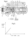
- a fluid flow control device 10 in accordance with the present invention controls the level of output flow from the control device dependent on the level of input flow to the control device from a fluid pump 12 (for example, a hydraulic fluid pump in the power steering system of a motor vehicle).
- the control device 10 comprises a housing 14 having an axially extending bore 16 therein.
- the bore 16 is closed at one end 18 of the housing 14 and is open at the other end 20 of the housing.
- a piston valve 22 is positioned within the bore 16 and is slidable therein. The piston valve 22 makes a seal with the bore 16 by way of O-ring seals 24.
- a helical coil spring 26 is positioned in the bore 16 between the closed end 18 and the piston valve 22 and acts on the piston valve to bias the piston valve away from the closed end.
- the bore 16 defines first and second pressure chambers 28,30, respectively, between the piston valve 22 and the open end 20 of the bore, the second pressure chamber being adjacent the piston valve.
- An input flow passage 32 which is connected to the output flow passage (not shown) of the fluid pump 12, opens into the first pressure chamber 28.
- a return flow passage 34 is connectable with the second pressure chamber 30 dependent on the position of the piston valve 22. In the position shown in Figure 2, the piston valve 22 closes the return flow passage 34.
- the return flow passage 34 is connected to the input flow passage (not shown) of the fluid pump 12 and/or a fluid reservoir (not shown).
- a droop flow device 36 is secured to the housing 14.
- the droop flow device 36 includes a fitting 37 which is secured in the open end 20 of the bore 16, preferably by way of a screw threaded connection 38, and which is sealed in the bore by an O-ring seal 40.
- the fitting 37 defines an output flow passage 42 for the control device 10.
- a guide tube 44 having an axially extending through bore 46 is secured to the fitting 37.
- the through bore 46 connects with the output flow passage 42 at one end 48, and has a valve seat 50 at the other end which is positioned in the second pressure chamber 30.
- the piston valve 22 is biased by the spring 26 into engagement with the valve seat 50 and, when the piston valve is in the position shown in Figures 1 and 2, closes the through bore 46 at said other end thereof.
- the guide tube 44 has a number of radially extending apertures 52 positioned between the valve seat 50 and the said one end 48 of the through bore 46.
- a plunger 54 makes a tight sliding fit on the outer surface 56 of the guide tube 44.
- the plunger 54 has a first portion 58 which is spaced from the outer surface 56 of the guide tube 44 to define an axially extending flow passage 60.
- the flow passage 60 opens into the second pressure chamber 30, and, when the plunger 54 is in the position shown in Figures 1 and 2, provides a fluid path between the second pressure chamber and the apertures 52.
- the end of the guide tube 44 adjacent the valve seat 50 is shaped to define a shoulder 62 which faces the plunger 54.
- a helical coil spring 64 is positioned within the flow passage 60 around the guide tube 44 and engages the shoulder 62 on the guide tube 44 and a shoulder 66 in the flow passage 60.
- the spring 64 acts on the plunger 54 to bias the plunger into engagement with a shoulder 68 on the fitting 37.
- This arrangement allows the droop flow device 36 to be pre-assembled as a one piece assembly prior to fixing in the housing 14, making assembly of the control device 10 easier.
- the positioning of the spring 64 around the guide tube 44 and within the flow passage 60 stabilises the mounting of the spring, and provides more accurate operation of the control device 10. This arrangement also prevents full compression of the spring 64 thereby reducing the risk of spring failure.
- the plunger 54 has a second portion 70 positioned within the first pressure chamber 28 which has an external surface 72 which slopes inwardly towards the guide tube 44, such that the external diameter of the plunger reduces as the plunger approaches the shoulder 68 on the fitting 37.
- this shape is not essential for the plunger 54 to move under the effects of the pressure difference between the first and second pressure chambers 28,30, it is a preferred arrangement which has benefits in terms of efficient operation of the control device 10.
- a flow restriction 74 is provided between the first and second pressure chambers 28,30. In this embodiment, the flow restriction 74 is defined by an inwardly directed shoulder 76 in the bore 16 between the first and second pressure chambers 28,30 and a flared end 78 on the plunger 54 where the flow passage 60 opens into the second pressure chamber.
- the increase in fluid pressure in the second pressure chamber 30 acts on the piston valve 22 to move the piston valve against the bias of the spring 26. This causes the piston valve 22 to move away from the valve seat 50 to open the said other end of the through bore 46, and to move to open the return flow passage 34, as shown in Figure 4. Also, as the input flow increases during this (second) stage of operation, the fluid pressure differential between the first pressure chamber 28 and the second pressure chamber 30 (due to the flow restriction 74) increases beyond a point which causes the plunger 54 to slide along the guide tube 44 in an axial direction against the bias of the spring 64.
- fluid continues to flow from the input flow passage 32 through the first pressure chamber 28 to the second pressure chamber 30 by way of flow restriction 74, and then through the flow passage 60, apertures 54, and through bore 46 to the output flow passage 42. Fluid also flows from the second pressure chamber 30 past the valve seat 50 into the through bore 46 and then to the output flow passage 42, and from the second pressure chamber into the return flow passage 34.
- the movement of the piston valve 22 relative to the housing 14, and the movement of the plunger 54 relative to the guide tube 44 continue until the level of the input flow reaches a second predetermined level B.
- the level of the output flow from the control device 10 remains substantially constant, and is the difference between the level of input flow and the level of flow through the return flow passage 34.
- a fourth stage of operation as the level of input flow increases beyond the third predetermined level C, the apertures 52 remain closed and fluid flows from the input flow passage 32 through the first pressure chamber 28 to the second pressure chamber 30 by way of flow restriction 74, and then from the second pressure chamber 30 past the valve seat 50 into the through bore 46 and then to the output flow passage 42, and from the second pressure chamber into the return flow passage 34.
- the valve 22 moves further against the bias of the spring 26 such that the level of the output flow through the output flow passage 42 remains substantially constant, and is the difference between the level of input flow and the level of flow through the return flow passage 34.
- the present arrangement is such that, during the various stages of operation of the control device, the level of the output flow is substantially unaffected by any back pressure generated in the output flow passage 42 because the operation of the droop flow device 36 is independent of the operation of the piston valve 22.
- the level of the output flow in the output flow passage 42, during the second stage of operation, is dependent on the number and diameter of the apertures 52 (that is, the total cross-sectional area of the apertures) and on the minimum cross-sectional area of the through bore 46 (which may be fixed by a portion 80 adjacent the valve seat 50).
- the level of the output flow in the output flow passage 42, during the fourth stage of operation, is dependent on the minimum cross-sectional area of the through bore 46 (which may be fixed by the portion 80 adjacent the valve seat 50) and on the minimum cross-sectional area of the return flow passage 34.
- the predetermined input flow levels B and C are determined by the load provided by the springs 26 and 64, and by the position of the apertures 52 in the guide tube 44.
- the present invention provides a fluid flow control device with a droop mechanism which is easy to form and assemble, and which uses a minimal number of parts.
Landscapes
- Engineering & Computer Science (AREA)
- General Engineering & Computer Science (AREA)
- Mechanical Engineering (AREA)
- Physics & Mathematics (AREA)
- Fluid Mechanics (AREA)
- General Physics & Mathematics (AREA)
- Automation & Control Theory (AREA)
- Safety Valves (AREA)
- Details Of Reciprocating Pumps (AREA)
Applications Claiming Priority (2)
| Application Number | Priority Date | Filing Date | Title |
|---|---|---|---|
| GB9602361A GB2310029B (en) | 1996-02-06 | 1996-02-06 | Fluid flow control device |
| GB9602361 | 1996-02-06 |
Publications (3)
| Publication Number | Publication Date |
|---|---|
| EP0789174A2 true EP0789174A2 (de) | 1997-08-13 |
| EP0789174A3 EP0789174A3 (de) | 1998-05-13 |
| EP0789174B1 EP0789174B1 (de) | 2002-10-30 |
Family
ID=10788187
Family Applications (1)
| Application Number | Title | Priority Date | Filing Date |
|---|---|---|---|
| EP19970200075 Expired - Lifetime EP0789174B1 (de) | 1996-02-06 | 1997-01-10 | Anordnung zur Durchflussregulierung von Flüssigkeit |
Country Status (3)
| Country | Link |
|---|---|
| EP (1) | EP0789174B1 (de) |
| DE (1) | DE69716656T2 (de) |
| GB (1) | GB2310029B (de) |
Cited By (1)
| Publication number | Priority date | Publication date | Assignee | Title |
|---|---|---|---|---|
| WO2019221785A1 (en) * | 2018-05-16 | 2019-11-21 | Parker-Hannifin Corporation | Valve comprising a dual piston assembly and method of forming a valve |
Families Citing this family (3)
| Publication number | Priority date | Publication date | Assignee | Title |
|---|---|---|---|---|
| US6799602B2 (en) | 2001-12-28 | 2004-10-05 | Visteon Global Technologies, Inc. | Combination fitting |
| CN107618022B (zh) * | 2017-09-14 | 2024-04-26 | 西南交通大学 | 容积调速液压系统和助力下肢外骨骼 |
| US11703132B2 (en) * | 2019-06-21 | 2023-07-18 | Emd Millipore Corporation | Zero dead leg valve |
Citations (5)
| Publication number | Priority date | Publication date | Assignee | Title |
|---|---|---|---|---|
| US4361166A (en) | 1980-01-24 | 1982-11-30 | Toyoda Koki Kabushiki Kaisha | Flow controlling apparatus for power steering, operating fluid |
| US4570667A (en) | 1984-09-17 | 1986-02-18 | General Motors Corporation | Demand responsive flow regulator valve |
| US4700733A (en) | 1984-09-25 | 1987-10-20 | Jidosha Kiki Co., Ltd. | Flow control valve |
| US4768540A (en) | 1987-04-20 | 1988-09-06 | Atsugi Motor Parts Company, Limited | Flow control apparatus |
| GB2277306A (en) | 1993-03-29 | 1994-10-26 | Toyoda Machine Works Ltd | Vehicle power steering apparatus with reduced output at high pump speeds |
Family Cites Families (3)
| Publication number | Priority date | Publication date | Assignee | Title |
|---|---|---|---|---|
| US5220939A (en) * | 1991-05-21 | 1993-06-22 | Koyo Seiko Co., Ltd. | Flow control apparatus |
| JPH05246335A (ja) * | 1992-03-06 | 1993-09-24 | Jidosha Kiki Co Ltd | 流量制御弁装置 |
| KR960012224B1 (ko) * | 1994-04-22 | 1996-09-18 | 한국기계연구원 | 파워 스티어링용 유량제어기구(Flow Control Mechanism for power Steering) |
-
1996
- 1996-02-06 GB GB9602361A patent/GB2310029B/en not_active Expired - Fee Related
-
1997
- 1997-01-10 DE DE1997616656 patent/DE69716656T2/de not_active Expired - Lifetime
- 1997-01-10 EP EP19970200075 patent/EP0789174B1/de not_active Expired - Lifetime
Patent Citations (5)
| Publication number | Priority date | Publication date | Assignee | Title |
|---|---|---|---|---|
| US4361166A (en) | 1980-01-24 | 1982-11-30 | Toyoda Koki Kabushiki Kaisha | Flow controlling apparatus for power steering, operating fluid |
| US4570667A (en) | 1984-09-17 | 1986-02-18 | General Motors Corporation | Demand responsive flow regulator valve |
| US4700733A (en) | 1984-09-25 | 1987-10-20 | Jidosha Kiki Co., Ltd. | Flow control valve |
| US4768540A (en) | 1987-04-20 | 1988-09-06 | Atsugi Motor Parts Company, Limited | Flow control apparatus |
| GB2277306A (en) | 1993-03-29 | 1994-10-26 | Toyoda Machine Works Ltd | Vehicle power steering apparatus with reduced output at high pump speeds |
Cited By (2)
| Publication number | Priority date | Publication date | Assignee | Title |
|---|---|---|---|---|
| WO2019221785A1 (en) * | 2018-05-16 | 2019-11-21 | Parker-Hannifin Corporation | Valve comprising a dual piston assembly and method of forming a valve |
| US11371759B2 (en) | 2018-05-16 | 2022-06-28 | Parker-Hannifin Corporation | Valve comprising a dual piston assembly and method of forming a valve |
Also Published As
| Publication number | Publication date |
|---|---|
| GB2310029B (en) | 2000-03-29 |
| DE69716656D1 (de) | 2002-12-05 |
| EP0789174B1 (de) | 2002-10-30 |
| DE69716656T2 (de) | 2003-03-20 |
| GB2310029A (en) | 1997-08-13 |
| GB9602361D0 (en) | 1996-04-03 |
| EP0789174A3 (de) | 1998-05-13 |
Similar Documents
| Publication | Publication Date | Title |
|---|---|---|
| US7568497B1 (en) | Combined check valve and pressure relief valve | |
| US20050061372A1 (en) | Pressure regulator assembly | |
| US5551664A (en) | Pilot controlled valve for motor vehicle tank systems | |
| US5722633A (en) | Solenoid valve for slip controlled brake systems | |
| EP0759122B1 (de) | Kraftstoffleitungsanlage ohne rücklaufleitung mit vakuumgesteuertem kraftstoffdruck | |
| US4016895A (en) | Flow control valve | |
| WO1993008416A1 (fr) | Amortisseur | |
| JPH05193492A (ja) | ハイドロリック式のブレーキ装置 | |
| US4371317A (en) | Hydraulic systems | |
| US5117860A (en) | Check valve | |
| US6938875B2 (en) | Proportional solenoid valve | |
| EP0789174B1 (de) | Anordnung zur Durchflussregulierung von Flüssigkeit | |
| US6206044B1 (en) | By-pass solenoid with integral check valve | |
| US6186750B1 (en) | Oil pump control valve spool with pilot pressure relief valve | |
| US5133186A (en) | Device for controlling the pressure in a hydraulic pressure system | |
| US11867298B2 (en) | System pressure valve for a hydraulic system of a motor vehicle transmission | |
| EP0084222B1 (de) | Hydraulische Kolbenpumpe | |
| US7320334B1 (en) | Valve Assembly | |
| CN112081915A (zh) | 恒压阀 | |
| US2724406A (en) | Relief valve | |
| EP0129097A2 (de) | Hubverstellschieber für eine Radialkolbenpumpe | |
| US6986363B1 (en) | Valve assembly for use in a hydraulic component | |
| GB2196092A (en) | Hydropneumatic suspension for motor vehicles | |
| US4389167A (en) | Pump having membrane actuated control valve to unload slave actuated inlet valve | |
| US4223694A (en) | Hydraulic circuit breaker |
Legal Events
| Date | Code | Title | Description |
|---|---|---|---|
| PUAI | Public reference made under article 153(3) epc to a published international application that has entered the european phase |
Free format text: ORIGINAL CODE: 0009012 |
|
| AK | Designated contracting states |
Kind code of ref document: A2 Designated state(s): DE FR IT |
|
| PUAL | Search report despatched |
Free format text: ORIGINAL CODE: 0009013 |
|
| AK | Designated contracting states |
Kind code of ref document: A3 Designated state(s): DE FR IT |
|
| 17P | Request for examination filed |
Effective date: 19981113 |
|
| 17Q | First examination report despatched |
Effective date: 20010514 |
|
| GRAG | Despatch of communication of intention to grant |
Free format text: ORIGINAL CODE: EPIDOS AGRA |
|
| GRAG | Despatch of communication of intention to grant |
Free format text: ORIGINAL CODE: EPIDOS AGRA |
|
| GRAH | Despatch of communication of intention to grant a patent |
Free format text: ORIGINAL CODE: EPIDOS IGRA |
|
| GRAH | Despatch of communication of intention to grant a patent |
Free format text: ORIGINAL CODE: EPIDOS IGRA |
|
| GRAA | (expected) grant |
Free format text: ORIGINAL CODE: 0009210 |
|
| AK | Designated contracting states |
Kind code of ref document: B1 Designated state(s): DE FR IT |
|
| REF | Corresponds to: |
Ref document number: 69716656 Country of ref document: DE Date of ref document: 20021205 |
|
| ET | Fr: translation filed | ||
| PLBE | No opposition filed within time limit |
Free format text: ORIGINAL CODE: 0009261 |
|
| STAA | Information on the status of an ep patent application or granted ep patent |
Free format text: STATUS: NO OPPOSITION FILED WITHIN TIME LIMIT |
|
| 26N | No opposition filed |
Effective date: 20030731 |
|
| REG | Reference to a national code |
Ref country code: FR Ref legal event code: TP |
|
| REG | Reference to a national code |
Ref country code: DE Ref legal event code: R081 Ref document number: 69716656 Country of ref document: DE Owner name: STEERING SOLUTIONS IP HOLDING CORP., SAGINAW, US Free format text: FORMER OWNER: GM GLOBAL TECHNOLOGY OPERATIONS, INC., DETROIT, MICH., US Effective date: 20110323 Ref country code: DE Ref legal event code: R081 Ref document number: 69716656 Country of ref document: DE Owner name: GM GLOBAL TECHNOLOGY OPERATIONS LLC (N. D. GES, US Free format text: FORMER OWNER: GM GLOBAL TECHNOLOGY OPERATIONS, INC., DETROIT, MICH., US Effective date: 20110323 Ref country code: DE Ref legal event code: R081 Ref document number: 69716656 Country of ref document: DE Owner name: GM GLOBAL TECHNOLOGY OPERATIONS LLC (N. D. GES, US Free format text: FORMER OWNER: GM GLOBAL TECHNOLOGY OPERATIONS, INC., DETROIT, US Effective date: 20110323 Ref country code: DE Ref legal event code: R081 Ref document number: 69716656 Country of ref document: DE Owner name: STEERING SOLUTIONS IP HOLDING CORP., US Free format text: FORMER OWNER: GM GLOBAL TECHNOLOGY OPERATIONS, INC., DETROIT, US Effective date: 20110323 |
|
| PGFP | Annual fee paid to national office [announced via postgrant information from national office to epo] |
Ref country code: FR Payment date: 20120130 Year of fee payment: 16 |
|
| PGFP | Annual fee paid to national office [announced via postgrant information from national office to epo] |
Ref country code: IT Payment date: 20120124 Year of fee payment: 16 |
|
| REG | Reference to a national code |
Ref country code: DE Ref legal event code: R082 Ref document number: 69716656 Country of ref document: DE Representative=s name: MANITZ, FINSTERWALD & PARTNER GBR, DE |
|
| REG | Reference to a national code |
Ref country code: DE Ref legal event code: R082 Ref document number: 69716656 Country of ref document: DE Representative=s name: MANITZ, FINSTERWALD & PARTNER GBR, DE Effective date: 20130313 Ref country code: DE Ref legal event code: R081 Ref document number: 69716656 Country of ref document: DE Owner name: GM GLOBAL TECHNOLOGY OPERATIONS LLC (N. D. GES, US Free format text: FORMER OWNER: GM GLOBAL TECHNOLOGY OPERATIONS LLC (N. D. GES. D. STAATES DELAWARE), DETROIT, MICH., US Effective date: 20130313 Ref country code: DE Ref legal event code: R081 Ref document number: 69716656 Country of ref document: DE Owner name: STEERING SOLUTIONS IP HOLDING CORP., SAGINAW, US Free format text: FORMER OWNER: GM GLOBAL TECHNOLOGY OPERATIONS LLC (N. D. GES. D. STAATES DELAWARE), DETROIT, MICH., US Effective date: 20130313 Ref country code: DE Ref legal event code: R081 Ref document number: 69716656 Country of ref document: DE Owner name: GM GLOBAL TECHNOLOGY OPERATIONS LLC (N. D. GES, US Free format text: FORMER OWNER: GM GLOBAL TECHNOLOGY OPERATIONS LLC (N. D. GES. D. STAATES DELAWARE), DETROIT, US Effective date: 20130313 Ref country code: DE Ref legal event code: R081 Ref document number: 69716656 Country of ref document: DE Owner name: STEERING SOLUTIONS IP HOLDING CORP., US Free format text: FORMER OWNER: GM GLOBAL TECHNOLOGY OPERATIONS LLC (N. D. GES. D. STAATES DELAWARE), DETROIT, US Effective date: 20130313 |
|
| REG | Reference to a national code |
Ref country code: FR Ref legal event code: ST Effective date: 20130930 |
|
| PG25 | Lapsed in a contracting state [announced via postgrant information from national office to epo] |
Ref country code: FR Free format text: LAPSE BECAUSE OF NON-PAYMENT OF DUE FEES Effective date: 20130131 |
|
| PG25 | Lapsed in a contracting state [announced via postgrant information from national office to epo] |
Ref country code: IT Free format text: LAPSE BECAUSE OF NON-PAYMENT OF DUE FEES Effective date: 20130110 |
|
| PGFP | Annual fee paid to national office [announced via postgrant information from national office to epo] |
Ref country code: DE Payment date: 20140129 Year of fee payment: 18 |
|
| REG | Reference to a national code |
Ref country code: DE Ref legal event code: R119 Ref document number: 69716656 Country of ref document: DE |
|
| REG | Reference to a national code |
Ref country code: FR Ref legal event code: TQ Owner name: GM GLOBAL TECHNOLOGY OPERATIONS LLC, US Effective date: 20150723 Ref country code: FR Ref legal event code: TQ Owner name: STEERING SOLUTIONS IP HOLDING CORPORATION, US Effective date: 20150723 Ref country code: FR Ref legal event code: CD Owner name: GM GLOBAL TECHNOLOGY OPERATIONS LLC, US Effective date: 20150723 Ref country code: FR Ref legal event code: CD Owner name: STEERING SOLUTIONS IP HOLDING CORPORATION, US Effective date: 20150723 |
|
| PG25 | Lapsed in a contracting state [announced via postgrant information from national office to epo] |
Ref country code: DE Free format text: LAPSE BECAUSE OF NON-PAYMENT OF DUE FEES Effective date: 20150801 |