EP0788855B1 - Casting device for producing closed deck type cylinder block and sand core used in the device - Google Patents
Casting device for producing closed deck type cylinder block and sand core used in the device Download PDFInfo
- Publication number
- EP0788855B1 EP0788855B1 EP97300787A EP97300787A EP0788855B1 EP 0788855 B1 EP0788855 B1 EP 0788855B1 EP 97300787 A EP97300787 A EP 97300787A EP 97300787 A EP97300787 A EP 97300787A EP 0788855 B1 EP0788855 B1 EP 0788855B1
- Authority
- EP
- European Patent Office
- Prior art keywords
- sand core
- core
- face
- sand
- holding
- Prior art date
- Legal status (The legal status is an assumption and is not a legal conclusion. Google has not performed a legal analysis and makes no representation as to the accuracy of the status listed.)
- Expired - Lifetime
Links
- 238000005266 casting Methods 0.000 title claims description 54
- 239000002184 metal Substances 0.000 claims description 60
- XLYOFNOQVPJJNP-UHFFFAOYSA-N water Substances O XLYOFNOQVPJJNP-UHFFFAOYSA-N 0.000 claims description 25
- 230000000295 complement effect Effects 0.000 claims description 11
- 238000000034 method Methods 0.000 claims description 5
- 230000002093 peripheral effect Effects 0.000 claims 2
- 239000004576 sand Substances 0.000 description 27
- 239000011230 binding agent Substances 0.000 description 3
- 238000004140 cleaning Methods 0.000 description 3
- 239000011248 coating agent Substances 0.000 description 3
- 238000003754 machining Methods 0.000 description 3
- 238000000576 coating method Methods 0.000 description 2
- 238000004519 manufacturing process Methods 0.000 description 2
- 238000012986 modification Methods 0.000 description 2
- 230000004048 modification Effects 0.000 description 2
- 230000015572 biosynthetic process Effects 0.000 description 1
- 238000002485 combustion reaction Methods 0.000 description 1
- 238000010276 construction Methods 0.000 description 1
- 238000000354 decomposition reaction Methods 0.000 description 1
- 230000001419 dependent effect Effects 0.000 description 1
- 238000006073 displacement reaction Methods 0.000 description 1
- 230000012447 hatching Effects 0.000 description 1
Images


Classifications
-
- B—PERFORMING OPERATIONS; TRANSPORTING
- B22—CASTING; POWDER METALLURGY
- B22D—CASTING OF METALS; CASTING OF OTHER SUBSTANCES BY THE SAME PROCESSES OR DEVICES
- B22D17/00—Pressure die casting or injection die casting, i.e. casting in which the metal is forced into a mould under high pressure
- B22D17/20—Accessories: Details
- B22D17/22—Dies; Die plates; Die supports; Cooling equipment for dies; Accessories for loosening and ejecting castings from dies
- B22D17/24—Accessories for locating and holding cores or inserts
-
- B—PERFORMING OPERATIONS; TRANSPORTING
- B22—CASTING; POWDER METALLURGY
- B22C—FOUNDRY MOULDING
- B22C21/00—Flasks; Accessories therefor
- B22C21/12—Accessories
- B22C21/14—Accessories for reinforcing or securing moulding materials or cores, e.g. gaggers, chaplets, pins, bars
-
- F—MECHANICAL ENGINEERING; LIGHTING; HEATING; WEAPONS; BLASTING
- F02—COMBUSTION ENGINES; HOT-GAS OR COMBUSTION-PRODUCT ENGINE PLANTS
- F02F—CYLINDERS, PISTONS OR CASINGS, FOR COMBUSTION ENGINES; ARRANGEMENTS OF SEALINGS IN COMBUSTION ENGINES
- F02F1/00—Cylinders; Cylinder heads
- F02F1/02—Cylinders; Cylinder heads having cooling means
- F02F1/10—Cylinders; Cylinder heads having cooling means for liquid cooling
- F02F2001/106—Cylinders; Cylinder heads having cooling means for liquid cooling using a closed deck, i.e. the water jacket is not open at the block top face
Definitions
- the present invention relates to a casting device for producing a closed deck type cylinder block and a sand core used in the casting device, and more particularly, to a combination of the casting device and the sand core, the combination being capable of performing casting operation while properly holding the sand core in the casting device.
- a closed deck type cylinder block in which bridge portions are provided bridging between a top deck of a cylinder head and outer end portions of cylinders in order to reduce engine vibration and to reinforce the cylinder block.
- this type of the cylinder block an upper open end of a water jacket is partly covered with the bridge portions.
- the upper open end of the water jacket constitutes windows each sectioned by the bridge portion.
- an undercut is provided in the water jacket below the bridge portions. Therefore, a sand core must be set at a position corresponding to the water jacket and the sand core must be collapsed after casting so as to remove the sand from the water jacket. Further, during casting operation, the sand core must be properly held within a metal mold.
- JP-A-1-178361 discloses a method for holding a sand core within the metal mold in producing the closed deck type cylinder block.
- a sand core 101 shown in Fig. 12 adapted for forming a water jacket which will surround three cylinders is provided with protruding portions 101a engageble with complementary recesses 102a formed in a slide core 102 shown in Fig. 13 in order to form windows at the engaging portions.
- a driving means (not shown) for driving holding pins 103 is provided independently of a driving means (not shown) adapted for driving a movable die toward and away from a stationary die (not shown).
- the holding pins 103 extends through the slide core 102 and projects into and retracts from a mold cavity by the holding pin drive means.
- the planer end face of the sand core 101 other than the protruding portions 101a is filled with a molten metal so as to produce the bridge portions at the end of the water jacket.
- the holding pins 103 project into the mold cavity, and the sand core 101 for forming the water jacket is temporarily mounted on the holding pins 103 as shown in Fig. 12. Then, the protruding portions 101a for forming the windows at the axially end portion of the sand core 101 are engaged with the complementary recesses 102a formed in the slide core 102, and at the same time, projections or core prints 101b projecting from the periphery of the sand core 101 are engaged with recessed portions (not shown) formed in the movable die so as to hold the sand core within the metal mold. Thereafter, the holding pins 103 are retracted from the mold cavity. By the projecting and retracting movement of the holding pins 103 relative to the mold cavity, the sand core 101 is held at a given position within the metal mold.
- the sand core 101 is ultimately held in the metal mold by the engagement between the protruding portions 101a and the complementary recessed portions 102a and by the engagement between the projections 101b and the recesses. Accordingly, in order to enhance positional accuracy of the sand core 101, clearance between the protruding portions 101a and the complementary recesses 102a for forming windows should be reduced. However, reduction in the clearance incurs accurate dimensional control, which in turn increases production cost. More specifically, the sand core 101 is generally subjected to coating in order to prevent the molten metal from entering into the sand core. However, the coating thickness may not be uniform, which may vary the clearance. Thus, adhesion amount of the coating agent over the protruding portions 101a must be precisely controlled.
- sand filling rate to the protruding portions 101a is inferior to that to the other part, and therefore, the protruding portions 101a provide insufficient mechanical strength and may be easily collapsed.
- the sand core is heated during casting and a binder contained therein may be burned by the heat, which causes reduction in strength of the sand core.
- the lowered strength is particularly actualized at the protruding portions 101a which may be easily collapsible.
- the protruding portions lOla are collapsed, and sand remain at the complementary recessed portions 102a.
- a device and a sand core for producing a closed deck type cylinder block having a top deck and being formed with a water jacket surrounding a plurality of juxtaposedly arrayed cylinder liners, the water jacket having an upper end partly open at the top deck for forming windows and partly closed by bridge portions, the device comprising a metal mold defining therein a mold cavity for casting the cylinder block, the sand core being for casting the water jacket in the cylinder block, characterized in that
- the sand core can be properly held by the engagement between the holding projections provided integrally with the metal mold and the holding bores formed in the sand core. Therefore, it is unnecessary to perform conventional positioning by the engagement between the recesses formed in the metal mold and the protruding portions provided at the sand core.
- precise control to the clearance between the metal mold and the sand core i.e., between the conventional recesses and protrusions, can be eliminated, yet improving positional accuracy of the sand core.
- the sand core can be held by the protruding components protruding from the metal mold and the holding bores formed in the sand core, even if the sand is released from the sand core, the residual sand on the protruding components can be easily acknowledged, and cleaning for removing the residual sand can be easily performed, to thus enhance productivity.
- the invention also provides a corresponding method of casting a closed desk type cylinder block using the device and the sand core above.
- the invention extends to a cylinder block casting formed by that method.
- a casting device for casting a closed deck type cylinder block and a sand core used in the casting device according to a first embodiment of the present invention will be described with reference to Figs. 1 through 6.
- the first embodiment is applied for casting a closed deck type cylinder block of a V-bank type six cylinder internal combustion engine.
- the sand core 1 shown in Fig. 1 is adapted for forming a water jacket surrounding three cylinders in the V-bank type six cylinder engine block.
- Figs. 2 and 4 show a state in which the sand core 1 is set within a mold cavity 6.
- the mold cavity 6 is defined by a slide core 2, a stationary die 8, a pair of first slide cores 22,22 and a pair of second slide cores 23,23.
- a slide core 2 has a cavity face 2d defining a part of the mold cavity 6.
- the cavity face 2d is formed with recesses 2a.
- the sand core 1 has an end face 1d in confrontation with the cavity face 2d.
- the end face 1d is provided with protruding portion la insertable into the recesses 2a for forming windows at a top end of the water jacket.
- a space S1 is defined between the cavity face 2d and portions other than the protruding portions la of the end face 1d.
- molten metal is filled into the space S1 so that bridge portions are provided at the top end of the water jacket. In other words, in the top end of the water jacket, neighboring windows are sectioned by the bridge portion.
- the pair of second slide cores 23,23 are formed with engaging holes 23a, 23a. Further, the sand core 1 is provided with a pair of core prints 1b,1b protruding from the periphery of the sand core 1. Each core print 1b is engageable with each engaging hole 23a, so that the sand core 1 is positioned in place in the mold cavity 6.
- the sand core 1 has a thickened wall portions le at positions adjacent the neighboring cylinders, and holding bores lc are formed from the end face 1d into the thickened wall portions le so as to allow holding projections 2b described later to extend into the holding bores 1c. Because the holding bores 1c are formed in the wall of the sand core 1 in an axial direction of the cylinder, the thickened walls le has a thickness greater than that of the remaining wall potion so as to sustain casing pressure.
- a reference numeral If designates a rear end surface of the sand core 1.
- a clearance S2 between the protruding portions 1a of the sand core 1 and the recessed portions 2a of the slide core 2 is relatively large, for example from 0.5 to 1.0 mm.
- the molten metal can be filled in the clearance S2 as a flash. Therefore, separated or residual sand in the recessed portions 2a can be removed together with the removal of the flash.
- molten metal pressure is applied to both axial end faces of the sand core 1, i.e., left side and right side of the sand core 1 in Fig. 2. Accordingly, the core prints 1b and complementary engagement holes 23a are required so as to prevent the sand core 1 from being moved in the axial direction of the cylinder within the mold cavity 6.
- each slide core 2, 2 is disposed at both sides of a movable die 12.
- the above described first and second slide cores 22,22 and 23,23 are movably disposed beside the slide cores 2,2.
- a combination of the stationary die 8, the slide cores 2, 2, the first and second slide cores 22,22, and 23,23 and the movable die 12 defines an outer contour of the cylinder block for the V-bank type six cylinder engine.
- Each slide core 2 includes a cylindrical projection 2c around which a cylinder liner 5 is fittable. Further, sand core holding protrusions 2b protrude from the slide core 2 in the axial direction of the cylinder liner 5 toward the mold cavity 6.
- the protrusions 2b are provided integrally with the slide core 2, and has a circular cross-section. An outer diameter of each protrusion 2b is gradually reduced toward its tip so as to provide a draft which facilitates removal of the protrusion 2b from the holding bore 1c after casting. Similarly, cross-section of the holding bore 1c has a complementary tapered shape. Incidentally, in Figs. 5 and 6, the cylinder liners 5 are supported by the cylindrical projection 2c such that each axis of the cylinder liner extends in a horizontal direction. Further, a runner 7 is provided for introducing the molten metal into the mold cavity 6.
- the holding projections 2b of the slide core 2 are engaged with the holding bores 1c of the sand core 1 so as to hold the sand core 1 to the slide core 2.
- the first and second slide cores 22,22 and 23,23 are moved to move the entire movable die toward the stationary die 8 so as to define the mold cavity 6 shown in Fig. 6.
- the molten metal is filled into the mold cavity 6 through the runner 7 for casting the cylinder block.
- the sand core 1 is held by the holding protrusions 2b, and therefore, the sand core 1 can be positioned precisely within the mold cavity 6. Further, because of the engagement between the core prints 1b and recesses 23a, the sand core 1 can be held stationarily in the metal mold without any displacement in the axial direction of the cylinder liner 5 despite of the molten metal pressure. Further, since relatively large clearance S2 is provided between the protrusions la and the complementary recess 2a for forming the window, the flash can be formed in the clearance S2 during casting. Therefore, even if sand in the protrusion la is separated from the core 1, the separated sand can be removed from the recess 2a together with the flash at the time of removal of the casted product from the metal mold.
- the binder contained in the sand core 1 may be decomposed due to the heat of the molten metal to lower the strength of the sand core 1, and sand constituting the protrusion la may be released therefrom.
- the molten metal can be easily entered into the large space clearance S2 to form the flash.
- the outer portion of the protrusion la is surrounded by the flash.
- the metal mold is opened and the casted product is removed therefrom.
- the released sand can also be removed together with the flash. Accordingly, the sand do not remain in the recess 2a.
- the casted product containing therein the sand core 1 is removed from the holding projection 2b, and sand may be affixed to the holding projection 2b.
- the holding projection 2b is of the protruding construction, sand adhesion therearound can be easily acknowledged, and the sand can be easily removed therefrom.
- the sand core 1 is discharged from the casted product through the formed windows of the water jacket. Further, machining is effected so as to form a female thread at each dimpled portion of the casted product, each dimpled portion being corresponding to each core print 1b. Then, threaded plugs (not shown) are threadably engaged with the female threads so as to plug the dimples.
- the holding projections 2b which belongs to the metal mold side are inserted into the holding bores 1c which belongs to the sand core side to hold the sand core 1 in the metal mold, and the engagement between the protruding portions la and the recesses 2a does not serve to hold the sand core 1. Accordingly, large clearance S2 can be provided between the protruding portions la and the recess 2a.
- the released sand can be removed from the recess when removing the flash provided at the large clearance S2. It should be noted that the flash is provided around the protruding portion and the flash can surely be provided because the molten metal can be easily entered into the large space S2.
- the sand core 1 is held by the engagement between the holding projection 2b protruding from the metal mold and the holding bore 1c formed in the sand core. Therefore, even if sand remains on the holding projection 2b, the remaining sand is easily visible because the holding projection 2b is of the projecting component. Thus, cleaning to the metal mold can be easily performed to enhance productivity.
- a casting device for casting a closed deck type cylinder block and a sand core used in the casting device according to a second embodiment of the present invention will be described with reference to Figs. 7 and 8.
- the clearance S2 is positively provided between the recess 2a and the protruding portion la of the sand core so as to positively introduce the molten metal into the clearance S2 to provide the flash therein. Therefore, after casting operation, flash removing operation is required. Further, because of the positive formation of the flash, the molten metal pressure is applied to the entire end surface 1d of the sand core 1.
- the second embodiment pertains to an improvement on these aspects.
- a sand core 51 in the second embodiment is similar to the sand core 1 of the first embodiment except that an end face 51d facing a slide core 52 is of a flat plane without any protruding portions (1a in Fig. 1), and core prints (1b in Fig. 1) are not provided at the periphery of the sand core 51.
- An end face 52d of the slide core 52 facing the top deck end 51d of the sand core 51 is formed with recesses 52a so as to form bridge portions.
- the end face 52d other than the recesses 52a will be in intimate contact with the flat end face 51d of the sand core 51 so as to form windows of the water jacket end.
- the end face 51d is of a simple planer arrangement.
- the end face 52d other than the recessed portions 52a of the slide core 52 may be referred to as protruding portions.
- the bridge portions will be provided after casting at hatching portions delineated on the end face 51d.
- a pair of slide cores 52,52 are provided besides the movable die 12, and the above described first and second slide cores 22,22 and 23A, 23A are movably disposed around the slide cores 52, 52.
- the stationary die 8, the slide cores 52, 52, the fist and second slide cores 22,22, 23A, 23A and the movable die 12 will form an outer contour of the V-bank type 6 cylinder engine block.
- Each of the slide cores 52 is provided with a cylindrical projection for supporting the cylinder liner 5.
- Each slide core 52 also provides holding projections 52b extending in the axial direction of the cylinder liner 5 and protruding from the end face 52d toward a mold cavity 56. Shape of the holding projections 52b and the holding bores 51c are identical with those of the first embodiment.
- the second slide cores 23A,23A are not formed with supporting recess (23a in the first embodiment) because core prints are not provided at the sand core 51.
- the front end face 51d of the sand core 51 is set in intimate contact with the end face 52d of the slide core 52.
- the sand core 51 is stably set in the mold cavity 56 by the engagement between the holding projections 52b and the holding bores 51c.
- advancing limit position of the sand core 51 in the axial direction of the cylinder liner 5 can be defined by the abutment between the end face 51d of the sand core 51 and the end face 52d of the slide core 52.
- the rearmost retracting limit position of the sand core in the axial direction is not defined, but large space is provided behind the rear end of the sand core 51 as shown in Fig. 8.
- the sand core 51 is urged toward the face 52d of the slide core 52.
- the sand core 51 is urged toward the advanced limit position because of the difference between F1 and F2, and consequently, positioning of the sand core 51 in the axial direction of the cylinder liner can be made.
- the core prints (1b in Fig. 1) can be eliminated.
- the molten metal is entered into the recessed portions 52a to form the bridge portions, whereas windows of the water jacket can be formed at the contacting portions between the front end 51d of the sand core 51 and the end face 52d of the slide core 52.
- the casted product is removed from the metal mold. In this case, problem of residual sand within the metal mold does not occur because the end face of the sand core does not have protruding portions (2a of Fig. 1) contrary to the first embodiment, but the end face 51d is of a planer arrangement.
- the engagement between the holding projections 52b and the holding bores 51c stably holds the sand core 51 within the mold cavity 56.
- the entire flat front face 51d of the sand core 51 can be contacted with the slide core 52 since it is unnecessary to positively provide the flash for the purpose of removing the residual sand, and as a result, contacting areas with the molten metal are different between the front end face 51d and the rear end face 51f of the sand core 51, to thus urgedly position the sand core 51 to the advanced limit position. Consequently, the core prints can be dispensed with, to thereby eliminating the above described machining required in the first embodiment.
- the sand core 51 per se can be easily produced because the end face 51d of the sand core 51 is of a planner arrangement without protruding portions.
- the flat or planer arrangement is also advantageous in that the problem of release of sand can be reduced or minimized.
- the depicted embodiments concern the production of the closed deck type V array six cylinder engine block.
- the invention can be applied to a closed deck type in-line engine block such as four cylinder in line engine block and six cylinder in line engine block.
- the cross-sectional configuration of the holding projections 2b or 52b and corresponding holding bores 1c or 51c is not limited to the circular shape, but generally triangular shape projections 2b' and bores 1c' shown in Figs. 9 and 10 and rectangular shape projections 2b" and bores 1c" shown in Figs. 9 and 11 are also available.
- the depth of the holding bores 1c can be varied dependent on the kind and size of the cylinder block and a posture of the sand core during casting as far as the sand core can be properly maintained in the metal mold.
- position of the holding bores 1c or 51c is not limited to the area le adjacent to the neighboring cylinders, but can be positioned other than the neighboring cylinders such as an area around 1c" in Fig. 9.
Landscapes
- Engineering & Computer Science (AREA)
- Mechanical Engineering (AREA)
- Cylinder Crankcases Of Internal Combustion Engines (AREA)
- Molds, Cores, And Manufacturing Methods Thereof (AREA)
Description
- The present invention relates to a casting device for producing a closed deck type cylinder block and a sand core used in the casting device, and more particularly, to a combination of the casting device and the sand core, the combination being capable of performing casting operation while properly holding the sand core in the casting device.
- A closed deck type cylinder block is known in which bridge portions are provided bridging between a top deck of a cylinder head and outer end portions of cylinders in order to reduce engine vibration and to reinforce the cylinder block. In this type of the cylinder block, an upper open end of a water jacket is partly covered with the bridge portions. In other words, the upper open end of the water jacket constitutes windows each sectioned by the bridge portion. Thus, an undercut is provided in the water jacket below the bridge portions. Therefore, a sand core must be set at a position corresponding to the water jacket and the sand core must be collapsed after casting so as to remove the sand from the water jacket. Further, during casting operation, the sand core must be properly held within a metal mold.
- JP-A-1-178361, on which the two part form of
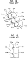
claim 1 is based, discloses a method for holding a sand core within the metal mold in producing the closed deck type cylinder block. According to the method, asand core 101 shown in Fig. 12 adapted for forming a water jacket which will surround three cylinders is provided with protrudingportions 101a engageble withcomplementary recesses 102a formed in aslide core 102 shown in Fig. 13 in order to form windows at the engaging portions. A driving means (not shown) for drivingholding pins 103 is provided independently of a driving means (not shown) adapted for driving a movable die toward and away from a stationary die (not shown). Theholding pins 103 extends through theslide core 102 and projects into and retracts from a mold cavity by the holding pin drive means. The planer end face of thesand core 101 other than theprotruding portions 101a is filled with a molten metal so as to produce the bridge portions at the end of the water jacket. - With this arrangement, the
holding pins 103 project into the mold cavity, and thesand core 101 for forming the water jacket is temporarily mounted on theholding pins 103 as shown in Fig. 12. Then, theprotruding portions 101a for forming the windows at the axially end portion of thesand core 101 are engaged with thecomplementary recesses 102a formed in theslide core 102, and at the same time, projections orcore prints 101b projecting from the periphery of thesand core 101 are engaged with recessed portions (not shown) formed in the movable die so as to hold the sand core within the metal mold. Thereafter, theholding pins 103 are retracted from the mold cavity. By the projecting and retracting movement of theholding pins 103 relative to the mold cavity, thesand core 101 is held at a given position within the metal mold. - The
sand core 101 is ultimately held in the metal mold by the engagement between theprotruding portions 101a and the complementary recessedportions 102a and by the engagement between theprojections 101b and the recesses. Accordingly, in order to enhance positional accuracy of thesand core 101, clearance between the protrudingportions 101a and thecomplementary recesses 102a for forming windows should be reduced. However, reduction in the clearance incurs accurate dimensional control, which in turn increases production cost. More specifically, thesand core 101 is generally subjected to coating in order to prevent the molten metal from entering into the sand core. However, the coating thickness may not be uniform, which may vary the clearance. Thus, adhesion amount of the coating agent over the protrudingportions 101a must be precisely controlled. - Further, in producing the sand core, sand filling rate to the protruding
portions 101a is inferior to that to the other part, and therefore, theprotruding portions 101a provide insufficient mechanical strength and may be easily collapsed. Furthermore, the sand core is heated during casting and a binder contained therein may be burned by the heat, which causes reduction in strength of the sand core. The lowered strength is particularly actualized at theprotruding portions 101a which may be easily collapsible. Moreover, if excessive local load is applied during take out of the casted product from the metal mold, the protruding portions lOla are collapsed, and sand remain at the complementary recessedportions 102a. If a subsequent sand core is set in the metal mold and the metal mold is closed while the residual sand remain at therecessed portions 102a, excessive force is applied to the sand core, so that the sand core may be collapsed prior to the casting. Consequently, sand remaining at therecessed portions 102a must be removed. However, it would be rather difficult to acknowledge the residual sand due to the blind space i.e., the recessed portions and cleaning work may be difficult due to the small concaved space of the recessed portions. Accordingly, productivity may be lowered. Furthermore, the casting device having themovable holding pins 103 is only available, otherwise the sand core cannot be set at a position within the metal mold. - According to the present invention there is provided a device and a sand core for producing a closed deck type cylinder block having a top deck and being formed with a water jacket surrounding a plurality of juxtaposedly arrayed cylinder liners, the water jacket having an upper end partly open at the top deck for forming windows and partly closed by bridge portions,
the device comprising a metal mold defining therein a mold cavity for casting the cylinder block, the sand core being for casting the water jacket in the cylinder block,
characterized in that - the device further comprises a plurality of holding projections integrally extending from the metal mold toward the mold cavity in an axial direction of the cylinder liner, and
- the sand core is formed with a plurality of holding bores complementary to respective holding projections and arranged to receive the holding projections extending thereinto for holding the sand core at a predetermined position within the mold cavity during casting.
-
- By the combination of the casting device and the sand core, the sand core can be properly held by the engagement between the holding projections provided integrally with the metal mold and the holding bores formed in the sand core. Therefore, it is unnecessary to perform conventional positioning by the engagement between the recesses formed in the metal mold and the protruding portions provided at the sand core. Thus, precise control to the clearance between the metal mold and the sand core, i.e., between the conventional recesses and protrusions, can be eliminated, yet improving positional accuracy of the sand core.
- Further, because the sand core can be held by the protruding components protruding from the metal mold and the holding bores formed in the sand core, even if the sand is released from the sand core, the residual sand on the protruding components can be easily acknowledged, and cleaning for removing the residual sand can be easily performed, to thus enhance productivity.
- The hereinafter described embodiments of the present invention can:
- provide a combination of a casting device and a sand core for producing a closed deck type cylinder block, the combination being capable of accurately holding the sand core within a metal mold for producing the closed deck type cylinder block having high dimensional accuracy;
- provide such combination capable of eliminating dimensional control with respect to the protruding parts of the sand core for forming the windows; and
- provide such combination in which residual sand can be easily acknowledged and removed at a sand core holding portion.
-
- The invention also provides a corresponding method of casting a closed desk type cylinder block using the device and the sand core above. The invention extends to a cylinder block casting formed by that method.
- The invention will be further described by way of example, with reference to the accompanying drawings, in which:
- Fig. 1 is a perspective view showing a sand core according to a first embodiment of this invention for forming a water jacket, the core being used for casting a closed deck type cylinder block;
- Fig. 2 is a cross-sectional view taken along the corrugated line II-II of Fig. 1, showing the sand core and a metal mold including a slide core in a casting device according to the first embodiment for casting the closed deck type cylinder block;
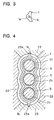
- Fig. 3 is a plan view showing a part of the sand core, the part including a holding bore;
- Fig. 4 is a cross-sectional view taken along the line IV-IV of Fig. 6 and showing the metal mold of the casting device and the sand core held in the casting device according to the first embodiment;
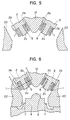
- Fig. 5 is a cross-sectional view showing an open state of the metal mold in the casting device and the sand core according to the first embodiment;
- Fig. 6 is a cross-sectional view showing a closed state of the metal mold in the casting device and the sand core according to the first embodiment;
- Fig. 7 is a perspective view showing a sand core according to a second embodiment of this invention for forming a water jacket, the core being used for casting a closed deck type cylinder block;
- Fig. 8 is a cross-sectional view showing the sand core of Fig. 7 and a metal mold including a slide core in a casting device according to the second embodiment for casting the closed deck type cylinder block;
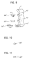
- Fig. 9 is a partial perspective view showing several modifications to the holding bore and a holding protrusion to be inserted thereinto;
- Fig. 10 is a cross-sectional view taken along the line X-X of Fig. 9;
- Fig. 11 is a cross-sectional view taken along the line XI-XI of Fig. 9;
- Fig. 12 is a perspective view showing a conventional sand core to be used for casting a closed deck type cylinder block; and
- Fig. 13 is a schematic cross-sectional view showing a part of a slide core and the conventional sand core held by the slide core.
-
- A casting device for casting a closed deck type cylinder block and a sand core used in the casting device according to a first embodiment of the present invention will be described with reference to Figs. 1 through 6. The first embodiment is applied for casting a closed deck type cylinder block of a V-bank type six cylinder internal combustion engine.
- The
sand core 1 shown in Fig. 1 is adapted for forming a water jacket surrounding three cylinders in the V-bank type six cylinder engine block. Figs. 2 and 4 show a state in which thesand core 1 is set within amold cavity 6. Themold cavity 6 is defined by aslide core 2, astationary die 8, a pair offirst slide cores second slide cores - As shown in Fig. 2, a
slide core 2 has acavity face 2d defining a part of themold cavity 6. Thecavity face 2d is formed withrecesses 2a. Thesand core 1 has anend face 1d in confrontation with thecavity face 2d. Theend face 1d is provided with protruding portion la insertable into therecesses 2a for forming windows at a top end of the water jacket. A space S1 is defined between thecavity face 2d and portions other than the protruding portions la of theend face 1d. During casting, molten metal is filled into the space S1 so that bridge portions are provided at the top end of the water jacket. In other words, in the top end of the water jacket, neighboring windows are sectioned by the bridge portion. - The pair of
second slide cores holes sand core 1 is provided with a pair ofcore prints sand core 1. Eachcore print 1b is engageable with eachengaging hole 23a, so that thesand core 1 is positioned in place in themold cavity 6. - As shown in Figs. 1 and 3, the
sand core 1 has a thickened wall portions le at positions adjacent the neighboring cylinders, and holding bores lc are formed from theend face 1d into the thickened wall portions le so as to allow holdingprojections 2b described later to extend into the holding bores 1c. Because the holding bores 1c are formed in the wall of thesand core 1 in an axial direction of the cylinder, the thickened walls le has a thickness greater than that of the remaining wall potion so as to sustain casing pressure. Incidentally, a reference numeral If designates a rear end surface of thesand core 1. - A clearance S2 between the protruding
portions 1a of thesand core 1 and the recessedportions 2a of theslide core 2 is relatively large, for example from 0.5 to 1.0 mm. By providing the large clearance, the molten metal can be filled in the clearance S2 as a flash. Therefore, separated or residual sand in the recessedportions 2a can be removed together with the removal of the flash. Because positive flashing is contemplated in the first embodiment at the clearance S2, molten metal pressure is applied to both axial end faces of thesand core 1, i.e., left side and right side of thesand core 1 in Fig. 2. Accordingly, the core prints 1b andcomplementary engagement holes 23a are required so as to prevent thesand core 1 from being moved in the axial direction of the cylinder within themold cavity 6. - As shown in Figs. 5 and 6, each
slide core movable die 12. The above described first andsecond slide cores slide cores stationary die 8, theslide cores second slide cores movable die 12 defines an outer contour of the cylinder block for the V-bank type six cylinder engine. Eachslide core 2 includes acylindrical projection 2c around which acylinder liner 5 is fittable. Further, sandcore holding protrusions 2b protrude from theslide core 2 in the axial direction of thecylinder liner 5 toward themold cavity 6. Theprotrusions 2b are provided integrally with theslide core 2, and has a circular cross-section. An outer diameter of eachprotrusion 2b is gradually reduced toward its tip so as to provide a draft which facilitates removal of theprotrusion 2b from the holding bore 1c after casting. Similarly, cross-section of the holding bore 1c has a complementary tapered shape. Incidentally, in Figs. 5 and 6, thecylinder liners 5 are supported by thecylindrical projection 2c such that each axis of the cylinder liner extends in a horizontal direction. Further, arunner 7 is provided for introducing the molten metal into themold cavity 6. - With this arrangement, while maintaining opening state of the metal mold shown in Fig. 5, the holding
projections 2b of theslide core 2 are engaged with the holding bores 1c of thesand core 1 so as to hold thesand core 1 to theslide core 2. After thecylinder liners 5 are fitted over thecylindrical projections 2c of theslide core 2, the first andsecond slide cores stationary die 8 so as to define themold cavity 6 shown in Fig. 6. Then, the molten metal is filled into themold cavity 6 through therunner 7 for casting the cylinder block. - During casting, the
sand core 1 is held by the holdingprotrusions 2b, and therefore, thesand core 1 can be positioned precisely within themold cavity 6. Further, because of the engagement between the core prints 1b and recesses 23a, thesand core 1 can be held stationarily in the metal mold without any displacement in the axial direction of thecylinder liner 5 despite of the molten metal pressure. Further, since relatively large clearance S2 is provided between the protrusions la and thecomplementary recess 2a for forming the window, the flash can be formed in the clearance S2 during casting. Therefore, even if sand in the protrusion la is separated from thecore 1, the separated sand can be removed from therecess 2a together with the flash at the time of removal of the casted product from the metal mold. - More specifically, the binder contained in the
sand core 1 may be decomposed due to the heat of the molten metal to lower the strength of thesand core 1, and sand constituting the protrusion la may be released therefrom. However, the molten metal can be easily entered into the large space clearance S2 to form the flash. Thus, the outer portion of the protrusion la is surrounded by the flash. After casting, the metal mold is opened and the casted product is removed therefrom. In this case, the released sand can also be removed together with the flash. Accordingly, the sand do not remain in therecess 2a. Further, the casted product containing therein thesand core 1 is removed from the holdingprojection 2b, and sand may be affixed to the holdingprojection 2b. However, because the holdingprojection 2b is of the protruding construction, sand adhesion therearound can be easily acknowledged, and the sand can be easily removed therefrom. - Then, the
sand core 1 is discharged from the casted product through the formed windows of the water jacket. Further, machining is effected so as to form a female thread at each dimpled portion of the casted product, each dimpled portion being corresponding to eachcore print 1b. Then, threaded plugs (not shown) are threadably engaged with the female threads so as to plug the dimples. - As described above, according to the first embodiment of the present invention, the holding
projections 2b which belongs to the metal mold side, are inserted into the holding bores 1c which belongs to the sand core side to hold thesand core 1 in the metal mold, and the engagement between the protruding portions la and therecesses 2a does not serve to hold thesand core 1. Accordingly, large clearance S2 can be provided between the protruding portions la and therecess 2a. Consequently, even if the mechanical strength of the sand core is reduced due to the decomposition of the binders contained therein by the heat of the molten metal so that the part of sand at the protruding portion is released, the released sand can be removed from the recess when removing the flash provided at the large clearance S2. It should be noted that the flash is provided around the protruding portion and the flash can surely be provided because the molten metal can be easily entered into the large space S2. - Further, the
sand core 1 is held by the engagement between the holdingprojection 2b protruding from the metal mold and the holding bore 1c formed in the sand core. Therefore, even if sand remains on the holdingprojection 2b, the remaining sand is easily visible because the holdingprojection 2b is of the projecting component. Thus, cleaning to the metal mold can be easily performed to enhance productivity. - A casting device for casting a closed deck type cylinder block and a sand core used in the casting device according to a second embodiment of the present invention will be described with reference to Figs. 7 and 8. According to the first embodiment, in order to remove the residual sand in the
recess 2a of theslide core 2, the clearance S2 is positively provided between therecess 2a and the protruding portion la of the sand core so as to positively introduce the molten metal into the clearance S2 to provide the flash therein. Therefore, after casting operation, flash removing operation is required. Further, because of the positive formation of the flash, the molten metal pressure is applied to theentire end surface 1d of thesand core 1. Because the molten metal pressure is always applied to the rear end surface 1f of thesand core 1, the core prints 1b are required for preventing the sand core from being deviated in the axial direction of the cylinder during casting. Consequently, the above described machining and plugging are required. The second embodiment pertains to an improvement on these aspects. - As shown in Figs. 7 and 8, a
sand core 51 in the second embodiment is similar to thesand core 1 of the first embodiment except that anend face 51d facing a slide core 52 is of a flat plane without any protruding portions (1a in Fig. 1), and core prints (1b in Fig. 1) are not provided at the periphery of thesand core 51. An end face 52d of the slide core 52 facing thetop deck end 51d of thesand core 51 is formed withrecesses 52a so as to form bridge portions. The end face 52d other than therecesses 52a will be in intimate contact with theflat end face 51d of thesand core 51 so as to form windows of the water jacket end. In other words, in the second embodiment, it is unnecessary to provide the protrudingportions 1a at theend face 51d of the sand core, but theend face 51d is of a simple planer arrangement. Incidentally, the end face 52d other than the recessedportions 52a of the slide core 52 may be referred to as protruding portions. Further, in Fig. 7, the bridge portions will be provided after casting at hatching portions delineated on theend face 51d. - Similar to the first embodiment, a pair of slide cores 52,52 are provided besides the
movable die 12, and the above described first andsecond slide cores stationary die 8, the slide cores 52, 52, the fist andsecond slide cores movable die 12 will form an outer contour of the V-bank type 6 cylinder engine block. Each of the slide cores 52 is provided with a cylindrical projection for supporting thecylinder liner 5. Each slide core 52 also provides holdingprojections 52b extending in the axial direction of thecylinder liner 5 and protruding from the end face 52d toward amold cavity 56. Shape of the holdingprojections 52b and the holding bores 51c are identical with those of the first embodiment. - The
second slide cores sand core 51. Thus, in the closing state of the metal mold, thefront end face 51d of thesand core 51 is set in intimate contact with the end face 52d of the slide core 52. With this state, thesand core 51 is stably set in themold cavity 56 by the engagement between the holdingprojections 52b and the holding bores 51c. - When filling the molten metal into the
mold cavity 56, advancing limit position of thesand core 51 in the axial direction of thecylinder liner 5 can be defined by the abutment between theend face 51d of thesand core 51 and the end face 52d of the slide core 52. On the other hand, the rearmost retracting limit position of the sand core in the axial direction is not defined, but large space is provided behind the rear end of thesand core 51 as shown in Fig. 8. However, because of the difference in molten metal pressures between thefront end face 51d and therear end face 51f of thesand core 51, thesand core 51 is urged toward the face 52d of the slide core 52. That is, the molten metal pressure force F1 applied to thefront end face 51d of thesand core 51 is F1 = P × (a - b), whereas the molten metal pressure F2 applied to therear end face 51f of thesand core 51 is F2 = P × a, where "P" is the casting pressure, "a" is an area of thefront end face 51d(orrear end face 51f) of thesand core 51, and "b" is the contacting area between thefront end face 51d and the end face 52d of the slide core 52. Accordingly, F2 is greater than F1. - In this way, the
sand core 51 is urged toward the advanced limit position because of the difference between F1 and F2, and consequently, positioning of thesand core 51 in the axial direction of the cylinder liner can be made. As a result, the core prints (1b in Fig. 1) can be eliminated. - Upon casting, the molten metal is entered into the recessed
portions 52a to form the bridge portions, whereas windows of the water jacket can be formed at the contacting portions between thefront end 51d of thesand core 51 and the end face 52d of the slide core 52. After casting, the casted product is removed from the metal mold. In this case, problem of residual sand within the metal mold does not occur because the end face of the sand core does not have protruding portions (2a of Fig. 1) contrary to the first embodiment, but theend face 51d is of a planer arrangement. - Similar to the first embodiment, according to the second embodiment, the engagement between the holding
projections 52b and the holding bores 51c stably holds thesand core 51 within themold cavity 56. However, contrary to the first embodiment, the entire flatfront face 51d of thesand core 51 can be contacted with the slide core 52 since it is unnecessary to positively provide the flash for the purpose of removing the residual sand, and as a result, contacting areas with the molten metal are different between thefront end face 51d and therear end face 51f of thesand core 51, to thus urgedly position thesand core 51 to the advanced limit position. Consequently, the core prints can be dispensed with, to thereby eliminating the above described machining required in the first embodiment. Further, in the second embodiment, thesand core 51 per se can be easily produced because theend face 51d of thesand core 51 is of a planner arrangement without protruding portions. The flat or planer arrangement is also advantageous in that the problem of release of sand can be reduced or minimized. - While the invention has been described in detail and with reference to the specific embodiments thereof, it would be apparent to those skilled in the art that various changes and modifications may be made. For example, in the above described embodiments, four holding
projections 2b (52b) and corresponding four holdingbores 1c (51c) are provided. However, the number can be not less than 2 as far as thesand core - Further, the depicted embodiments concern the production of the closed deck type V array six cylinder engine block. However, the invention can be applied to a closed deck type in-line engine block such as four cylinder in line engine block and six cylinder in line engine block.
- Further, the cross-sectional configuration of the holding
projections triangular shape projections 2b' and bores 1c' shown in Figs. 9 and 10 andrectangular shape projections 2b" and bores 1c" shown in Figs. 9 and 11 are also available. Furthermore, the depth of the holding bores 1c can be varied dependent on the kind and size of the cylinder block and a posture of the sand core during casting as far as the sand core can be properly maintained in the metal mold. Furthermore, position of the holding bores 1c or 51c is not limited to the area le adjacent to the neighboring cylinders, but can be positioned other than the neighboring cylinders such as an area around 1c" in Fig. 9.
Claims (7)
- A device and a sand core (1;51) for producing a closed deck type cylinder block having a top deck and being formed with a water jacket surrounding a plurality of juxtaposedly arrayed cylinder liners (5), the water jacket having an upper end partly open at the top deck for forming windows and partly closed by bridge portions,
the device comprising a metal mold (2, 8, 22, 23; 52, 8, 22, 23) defining therein a mold cavity (6; 56) for casting the cylinder block, the sand core (1;51) being for casting the water jacket in the cylinder block,
characterized in thatthe device further comprises a plurality of holding projections (2b; 52b) integrally extending from the metal mold (2;52) toward the mold cavity (6; 56) in an axial direction of the cylinder liner (5), andthe sand core (1) is formed with a plurality of holding bores (1c, 51c) complementary to respective holding projections and arranged to receive the holding projections extending thereinto (2b; 52b) for holding the sand core (1; 51) at a predetermined position within the mold cavity (6;56) during casting. - A device and sand core as claimed in claim 1, whereinthe metal mold includes a slide core (2) having an end face (2d) defining a part of the mold cavity (6), the end face (2d) being formed with a plurality of recesses (2a), andthe sand core has a top deck end face (1d) formed with protrusions (1a) each engageable with a respective recess (2a) of the slide core (2), a space (S2) being provided between respective recesses (2a) and the protrusions (la) for providing a flash at the space.
- A device and sand core as claimed in claim 2, wherein
the sand core (1) comprises:a wall portion having the top deck end face (1d) and an outer peripheral surface, the wall portion having a shape identical with the water jacket; andcore prints (1b) extending from the outer peripheral surface, andthe metal mold (23) further comprises a pair of slide cores (23) formed with engaging recesses (23a) for engaging with the core prints (1b) so as to prevent the sand core (1) from being moved in the axial direction of the cylinder lines (5). - A device and sand core as claimed in claim 1, whereinthe metal mold comprises a slide core (52) having an end face (52d) defining a part of the mold cavity (56), the end face (52d) being formed with a plurality of recesses (52a), andthe sand core (51) has a planer top deck end face (51d) in intimate contact with the end face (52d) of the slide core (52) at portions other than the plurality of recesses (52a) during casting, the contacting area between the planer top deck end face (51d) of the sand core (51) and the end face (52d) of the slide core (52) forming the windows.
- A device and sand core as claimed in any one of the preceding claims, wherein the holding projection (2b) have a tapered shape in which the outer diameter gradually reduces toward its tip, and the holding bore (1c) have a complementary tapered shape for providing a draft.
- A device and sand core as claimed in any one of the preceding claims, wherein the sand core (1) comprises a wall having a shape identical with the water jacket, the wall of the sand core (1) having an uneven thickness around the cylinders, the thickness of the portions (1e) of the wall between neighbouring cylinders being greater than the thickness of the remaining portions of the wall, the holding bores (1c) being formed in the thicker portions (1e).
- A method of casting a closed deck type cylinder block using a device and sand core as defined in any one of the preceding claims.
Applications Claiming Priority (6)
| Application Number | Priority Date | Filing Date | Title |
|---|---|---|---|
| JP4837896 | 1996-02-09 | ||
| JP48378/96 | 1996-02-09 | ||
| JP4837896 | 1996-02-09 | ||
| JP20880096A JP3274069B2 (en) | 1996-02-09 | 1996-07-19 | Combination of closed deck type cylinder block casting device and sand core used in the device |
| JP208800/96 | 1996-07-19 | ||
| JP20880096 | 1996-07-19 |
Publications (2)
| Publication Number | Publication Date |
|---|---|
| EP0788855A1 EP0788855A1 (en) | 1997-08-13 |
| EP0788855B1 true EP0788855B1 (en) | 2001-05-09 |
Family
ID=26388628
Family Applications (1)
| Application Number | Title | Priority Date | Filing Date |
|---|---|---|---|
| EP97300787A Expired - Lifetime EP0788855B1 (en) | 1996-02-09 | 1997-02-07 | Casting device for producing closed deck type cylinder block and sand core used in the device |
Country Status (4)
| Country | Link |
|---|---|
| US (1) | US5720334A (en) |
| EP (1) | EP0788855B1 (en) |
| JP (1) | JP3274069B2 (en) |
| DE (1) | DE69704728T2 (en) |
Families Citing this family (20)
| Publication number | Priority date | Publication date | Assignee | Title |
|---|---|---|---|---|
| US5850814A (en) * | 1998-04-07 | 1998-12-22 | Ford Global Technologies, Inc. | Cylinder bore isolator core for casting engine cylinder blocks |
| JP2000199452A (en) * | 1998-12-28 | 2000-07-18 | Ryobi Ltd | Closed deck type cylinder block and manufacture thereof |
| DE10112135A1 (en) * | 2001-03-14 | 2002-10-02 | Bayerische Motoren Werke Ag | Cast core for the coolant jacket of a crankcase of an internal combustion engine |
| KR100435961B1 (en) * | 2001-10-08 | 2004-06-12 | 현대자동차주식회사 | Manufacturing method for water jacket throttle of cylinder head |
| DE10224130A1 (en) * | 2002-05-29 | 2003-12-18 | Vaw Mandl & Berger Gmbh Linz | Light metal cylinder block casting, for an IC motor, has cylinder liners of a metal which melts when the molten metal is poured into the mold, to give a metallurgical fusion at least at the liner edges |
| DE10259044A1 (en) * | 2002-12-17 | 2004-07-08 | Bayerische Motoren Werke Ag | Production of cylinder block in a composite mold used in the manufacture of liquid cooled internal combustion engine with avoidance of large weight deviations in pressing the cylinder jacket wall under the casting pressure |
| JP4662178B2 (en) * | 2004-11-01 | 2011-03-30 | 株式会社豊田自動織機 | Pressure vessel, compressor and cylinder block casting method |
| JP4439424B2 (en) * | 2005-03-30 | 2010-03-24 | 本田技研工業株式会社 | Method for mounting casting sand core to mold and casting sand core |
| DE102005043193A1 (en) * | 2005-09-09 | 2007-03-15 | Ks Aluminium-Technologie Ag | Cylinder crankcase for motor vehicles |
| DE102006003104B3 (en) * | 2006-01-18 | 2007-08-23 | Schneider Form Gmbh | Gate valve for die-casting mold producing V-engine blocks, includes readily-replaceable water jacket insert, used when casting cavity of cylinder |
| JP4595919B2 (en) * | 2006-10-19 | 2010-12-08 | トヨタ自動車株式会社 | Water jacket core, cylinder block and manufacturing method thereof |
| DE102007004050B4 (en) | 2007-01-22 | 2010-03-18 | Ks Aluminium-Technologie Gmbh | Device for producing a cylinder crankcase |
| KR100902865B1 (en) * | 2008-10-30 | 2009-06-16 | 강옥수 | Manufacturing method for pb pipe coupler |
| KR100933749B1 (en) * | 2009-01-22 | 2009-12-24 | 강옥수 | Connection structure of wall embedded faucet |
| EP2441537A1 (en) * | 2010-10-18 | 2012-04-18 | Siemens Aktiengesellschaft | Tool for producing cores with variable pins and method for producing a core |
| CN102476180A (en) * | 2010-11-23 | 2012-05-30 | 苏州春兴精工股份有限公司 | Mold clamping solution suitable for flat thin-walled piece |
| DE102010054496B4 (en) * | 2010-12-14 | 2020-06-18 | Volkswagen Ag | Casting-made electric motor housing part for an electric motor |
| CN104607612B (en) * | 2014-11-05 | 2017-10-20 | 镁联科技(芜湖)有限公司 | Compacting tool set and method of squeeze forming |
| CN109158538A (en) * | 2018-11-14 | 2019-01-08 | 禹州市昆仑模具有限公司 | A lower die for contact-coated sand die |
| CN112743039A (en) * | 2021-01-14 | 2021-05-04 | 沈阳铁路信号有限责任公司 | One-outlet-multiple efficient sand core mold |
Family Cites Families (7)
| Publication number | Priority date | Publication date | Assignee | Title |
|---|---|---|---|---|
| CH640160A5 (en) * | 1979-07-05 | 1983-12-30 | Fischer Ag Georg | MOULD WITH core puller. |
| GB2068801A (en) * | 1980-02-05 | 1981-08-19 | Nl Industries Inc | Expendable cores for die casting |
| JP2648865B2 (en) * | 1988-01-11 | 1997-09-03 | リョービ株式会社 | Sand core holding method and holding device |
| US4981168A (en) * | 1989-07-11 | 1991-01-01 | Farley, Inc. | Mandrel holds expendable core in casting die |
| JP2579004B2 (en) * | 1989-12-05 | 1997-02-05 | ドーラー・ジヤービス・リミテツド・パートナーシツプ | Collapsible sand core for cylinder of engine block |
| JPH0815647B2 (en) * | 1990-06-28 | 1996-02-21 | 宇部興産株式会社 | Engine block casting equipment |
| JPH0671409A (en) * | 1992-08-28 | 1994-03-15 | Ryobi Ltd | Die for casting water-cooled cylinder block |
-
1996
- 1996-07-19 JP JP20880096A patent/JP3274069B2/en not_active Expired - Fee Related
-
1997
- 1997-02-07 EP EP97300787A patent/EP0788855B1/en not_active Expired - Lifetime
- 1997-02-07 US US08/797,314 patent/US5720334A/en not_active Expired - Lifetime
- 1997-02-07 DE DE69704728T patent/DE69704728T2/en not_active Expired - Fee Related
Also Published As
| Publication number | Publication date |
|---|---|
| JP3274069B2 (en) | 2002-04-15 |
| US5720334A (en) | 1998-02-24 |
| EP0788855A1 (en) | 1997-08-13 |
| DE69704728T2 (en) | 2002-04-18 |
| DE69704728D1 (en) | 2001-06-13 |
| JPH09271924A (en) | 1997-10-21 |
Similar Documents
| Publication | Publication Date | Title |
|---|---|---|
| US5720334A (en) | Casting device for producing closed deck type cylinder block and sand core used in the device | |
| CA2499317C (en) | Method and apparatus for die-casting a v-block for an internal combustion engine | |
| EP1084812B1 (en) | Method of manufacturing gear case | |
| JPH07108350A (en) | Casting mold manufacturing method | |
| JPH0242582B2 (en) | ||
| US6415848B1 (en) | Metal mold arrangement for producing cylinder block | |
| JP3248896B2 (en) | Combination of a closed deck type cylinder block casting device and a sand core used in the device | |
| EP0662360B1 (en) | Process for casting pipe with transversal holes | |
| JP3944984B2 (en) | Mold for resin molding production | |
| JP2648865B2 (en) | Sand core holding method and holding device | |
| JP2899362B2 (en) | Gravity casting mold for the production of piston blanks | |
| JP4257167B2 (en) | Cylinder head manufacturing method and apparatus | |
| KR19980057286A (en) | Die frame with fixed support pin | |
| CN213452826U (en) | Novel die casting | |
| JPH0732089A (en) | Core assembly structure for casting | |
| GB2141957A (en) | Process for manufacturing internally cast single threaded nut | |
| JPH01288417A (en) | Manufacture of bicolor lens | |
| CN210080656U (en) | Oil sprayer pressing plate based on precision casting integrated into one piece | |
| JPS61182442A (en) | Manufacture of cylinder block | |
| JPH02169223A (en) | Injection molding die | |
| JPH0347722Y2 (en) | ||
| KR200283404Y1 (en) | Investment casting metal mould for car to prevent hole―clogging | |
| JPH049078Y2 (en) | ||
| JP2907385B2 (en) | Backfill method of frame adjustment hole in PC formwork | |
| JPS6140501Y2 (en) |
Legal Events
| Date | Code | Title | Description |
|---|---|---|---|
| PUAI | Public reference made under article 153(3) epc to a published international application that has entered the european phase |
Free format text: ORIGINAL CODE: 0009012 |
|
| AK | Designated contracting states |
Kind code of ref document: A1 Designated state(s): DE GB |
|
| 17P | Request for examination filed |
Effective date: 19971015 |
|
| 17Q | First examination report despatched |
Effective date: 19990625 |
|
| GRAG | Despatch of communication of intention to grant |
Free format text: ORIGINAL CODE: EPIDOS AGRA |
|
| GRAG | Despatch of communication of intention to grant |
Free format text: ORIGINAL CODE: EPIDOS AGRA |
|
| GRAH | Despatch of communication of intention to grant a patent |
Free format text: ORIGINAL CODE: EPIDOS IGRA |
|
| GRAH | Despatch of communication of intention to grant a patent |
Free format text: ORIGINAL CODE: EPIDOS IGRA |
|
| GRAA | (expected) grant |
Free format text: ORIGINAL CODE: 0009210 |
|
| AK | Designated contracting states |
Kind code of ref document: B1 Designated state(s): DE GB |
|
| REF | Corresponds to: |
Ref document number: 69704728 Country of ref document: DE Date of ref document: 20010613 |
|
| REG | Reference to a national code |
Ref country code: GB Ref legal event code: IF02 |
|
| PLBE | No opposition filed within time limit |
Free format text: ORIGINAL CODE: 0009261 |
|
| STAA | Information on the status of an ep patent application or granted ep patent |
Free format text: STATUS: NO OPPOSITION FILED WITHIN TIME LIMIT |
|
| 26N | No opposition filed | ||
| PGFP | Annual fee paid to national office [announced via postgrant information from national office to epo] |
Ref country code: DE Payment date: 20090206 Year of fee payment: 13 |
|
| PGFP | Annual fee paid to national office [announced via postgrant information from national office to epo] |
Ref country code: GB Payment date: 20090204 Year of fee payment: 13 |
|
| GBPC | Gb: european patent ceased through non-payment of renewal fee |
Effective date: 20100207 |
|
| PG25 | Lapsed in a contracting state [announced via postgrant information from national office to epo] |
Ref country code: DE Free format text: LAPSE BECAUSE OF NON-PAYMENT OF DUE FEES Effective date: 20100901 |
|
| PG25 | Lapsed in a contracting state [announced via postgrant information from national office to epo] |
Ref country code: GB Free format text: LAPSE BECAUSE OF NON-PAYMENT OF DUE FEES Effective date: 20100207 |