EP0788671B1 - Connector for elongate cable - Google Patents
Connector for elongate cable Download PDFInfo
- Publication number
- EP0788671B1 EP0788671B1 EP95938942A EP95938942A EP0788671B1 EP 0788671 B1 EP0788671 B1 EP 0788671B1 EP 95938942 A EP95938942 A EP 95938942A EP 95938942 A EP95938942 A EP 95938942A EP 0788671 B1 EP0788671 B1 EP 0788671B1
- Authority
- EP
- European Patent Office
- Prior art keywords
- heating cable
- connection
- shell
- elongate
- connector
- Prior art date
- Legal status (The legal status is an assumption and is not a legal conclusion. Google has not performed a legal analysis and makes no representation as to the accuracy of the status listed.)
- Expired - Lifetime
Links
- 238000007789 sealing Methods 0.000 claims abstract description 37
- 238000010438 heat treatment Methods 0.000 claims description 144
- 229910052751 metal Inorganic materials 0.000 claims description 34
- 239000002184 metal Substances 0.000 claims description 34
- 239000000463 material Substances 0.000 claims description 26
- 238000009434 installation Methods 0.000 claims description 12
- 239000000203 mixture Substances 0.000 claims description 6
- 230000013011 mating Effects 0.000 claims description 5
- 238000006073 displacement reaction Methods 0.000 claims description 4
- 238000009413 insulation Methods 0.000 claims description 4
- 239000000499 gel Substances 0.000 description 10
- 238000003780 insertion Methods 0.000 description 10
- 230000037431 insertion Effects 0.000 description 10
- 239000010410 layer Substances 0.000 description 8
- 229920000642 polymer Polymers 0.000 description 7
- 239000000758 substrate Substances 0.000 description 7
- 230000000712 assembly Effects 0.000 description 6
- 238000000429 assembly Methods 0.000 description 6
- 230000000007 visual effect Effects 0.000 description 6
- 229920001940 conductive polymer Polymers 0.000 description 5
- 229920000728 polyester Polymers 0.000 description 5
- 239000012528 membrane Substances 0.000 description 4
- 238000000034 method Methods 0.000 description 4
- 229920003023 plastic Polymers 0.000 description 4
- -1 polybutylene terephthalate Polymers 0.000 description 4
- 238000012544 monitoring process Methods 0.000 description 3
- 239000004033 plastic Substances 0.000 description 3
- 239000004417 polycarbonate Substances 0.000 description 3
- 229920000515 polycarbonate Polymers 0.000 description 3
- 239000000853 adhesive Substances 0.000 description 2
- 230000001070 adhesive effect Effects 0.000 description 2
- 239000000919 ceramic Substances 0.000 description 2
- 238000013461 design Methods 0.000 description 2
- 238000010292 electrical insulation Methods 0.000 description 2
- 229920006351 engineering plastic Polymers 0.000 description 2
- 230000007613 environmental effect Effects 0.000 description 2
- 239000000945 filler Substances 0.000 description 2
- 230000000704 physical effect Effects 0.000 description 2
- 239000003566 sealing material Substances 0.000 description 2
- 229910001369 Brass Inorganic materials 0.000 description 1
- RYGMFSIKBFXOCR-UHFFFAOYSA-N Copper Chemical compound [Cu] RYGMFSIKBFXOCR-UHFFFAOYSA-N 0.000 description 1
- 239000004677 Nylon Substances 0.000 description 1
- 240000005428 Pistacia lentiscus Species 0.000 description 1
- 239000004952 Polyamide Substances 0.000 description 1
- 239000004698 Polyethylene Substances 0.000 description 1
- 239000004721 Polyphenylene oxide Substances 0.000 description 1
- 239000004734 Polyphenylene sulfide Substances 0.000 description 1
- 239000004743 Polypropylene Substances 0.000 description 1
- 238000005299 abrasion Methods 0.000 description 1
- NIXOWILDQLNWCW-UHFFFAOYSA-N acrylic acid group Chemical group C(C=C)(=O)O NIXOWILDQLNWCW-UHFFFAOYSA-N 0.000 description 1
- 239000012790 adhesive layer Substances 0.000 description 1
- 229910052782 aluminium Inorganic materials 0.000 description 1
- XAGFODPZIPBFFR-UHFFFAOYSA-N aluminium Chemical compound [Al] XAGFODPZIPBFFR-UHFFFAOYSA-N 0.000 description 1
- 230000004888 barrier function Effects 0.000 description 1
- 238000005452 bending Methods 0.000 description 1
- DMFGNRRURHSENX-UHFFFAOYSA-N beryllium copper Chemical compound [Be].[Cu] DMFGNRRURHSENX-UHFFFAOYSA-N 0.000 description 1
- 239000010951 brass Substances 0.000 description 1
- 239000006229 carbon black Substances 0.000 description 1
- 230000008859 change Effects 0.000 description 1
- 230000006835 compression Effects 0.000 description 1
- 238000007906 compression Methods 0.000 description 1
- 238000007796 conventional method Methods 0.000 description 1
- 229910052802 copper Inorganic materials 0.000 description 1
- 239000010949 copper Substances 0.000 description 1
- 230000001419 dependent effect Effects 0.000 description 1
- 230000008014 freezing Effects 0.000 description 1
- 238000007710 freezing Methods 0.000 description 1
- 239000011521 glass Substances 0.000 description 1
- 238000001746 injection moulding Methods 0.000 description 1
- 238000004519 manufacturing process Methods 0.000 description 1
- 230000007246 mechanism Effects 0.000 description 1
- 239000010445 mica Substances 0.000 description 1
- 229910052618 mica group Inorganic materials 0.000 description 1
- 229920001778 nylon Polymers 0.000 description 1
- 230000035515 penetration Effects 0.000 description 1
- 229920002492 poly(sulfone) Polymers 0.000 description 1
- 229920002647 polyamide Polymers 0.000 description 1
- 229920001707 polybutylene terephthalate Polymers 0.000 description 1
- 229920000573 polyethylene Polymers 0.000 description 1
- 229920000139 polyethylene terephthalate Polymers 0.000 description 1
- 239000005020 polyethylene terephthalate Substances 0.000 description 1
- 229920005597 polymer membrane Polymers 0.000 description 1
- 229920006380 polyphenylene oxide Polymers 0.000 description 1
- 229920000069 polyphenylene sulfide Polymers 0.000 description 1
- 229920001155 polypropylene Polymers 0.000 description 1
- 229920001296 polysiloxane Polymers 0.000 description 1
- 230000008569 process Effects 0.000 description 1
- 238000012545 processing Methods 0.000 description 1
- 229920002379 silicone rubber Polymers 0.000 description 1
- 239000004945 silicone rubber Substances 0.000 description 1
- 239000003381 stabilizer Substances 0.000 description 1
- 239000000454 talc Substances 0.000 description 1
- 229910052623 talc Inorganic materials 0.000 description 1
- 238000009864 tensile test Methods 0.000 description 1
- 238000012360 testing method Methods 0.000 description 1
- 238000001721 transfer moulding Methods 0.000 description 1
- 239000012780 transparent material Substances 0.000 description 1
Images


Classifications
-
- H—ELECTRICITY
- H01—ELECTRIC ELEMENTS
- H01R—ELECTRICALLY-CONDUCTIVE CONNECTIONS; STRUCTURAL ASSOCIATIONS OF A PLURALITY OF MUTUALLY-INSULATED ELECTRICAL CONNECTING ELEMENTS; COUPLING DEVICES; CURRENT COLLECTORS
- H01R13/00—Details of coupling devices of the kinds covered by groups H01R12/70 or H01R24/00 - H01R33/00
- H01R13/46—Bases; Cases
- H01R13/52—Dustproof, splashproof, drip-proof, waterproof, or flameproof cases
- H01R13/5205—Sealing means between cable and housing, e.g. grommet
-
- H—ELECTRICITY
- H01—ELECTRIC ELEMENTS
- H01R—ELECTRICALLY-CONDUCTIVE CONNECTIONS; STRUCTURAL ASSOCIATIONS OF A PLURALITY OF MUTUALLY-INSULATED ELECTRICAL CONNECTING ELEMENTS; COUPLING DEVICES; CURRENT COLLECTORS
- H01R4/00—Electrically-conductive connections between two or more conductive members in direct contact, i.e. touching one another; Means for effecting or maintaining such contact; Electrically-conductive connections having two or more spaced connecting locations for conductors and using contact members penetrating insulation
- H01R4/58—Electrically-conductive connections between two or more conductive members in direct contact, i.e. touching one another; Means for effecting or maintaining such contact; Electrically-conductive connections having two or more spaced connecting locations for conductors and using contact members penetrating insulation characterised by the form or material of the contacting members
- H01R4/64—Connections between or with conductive parts having primarily a non-electric function, e.g. frame, casing, rail
- H01R4/646—Connections between or with conductive parts having primarily a non-electric function, e.g. frame, casing, rail for cables or flexible cylindrical bodies
-
- H—ELECTRICITY
- H02—GENERATION; CONVERSION OR DISTRIBUTION OF ELECTRIC POWER
- H02G—INSTALLATION OF ELECTRIC CABLES OR LINES, OR OF COMBINED OPTICAL AND ELECTRIC CABLES OR LINES
- H02G15/00—Cable fittings
- H02G15/013—Sealing means for cable inlets
-
- H—ELECTRICITY
- H02—GENERATION; CONVERSION OR DISTRIBUTION OF ELECTRIC POWER
- H02G—INSTALLATION OF ELECTRIC CABLES OR LINES, OR OF COMBINED OPTICAL AND ELECTRIC CABLES OR LINES
- H02G15/00—Cable fittings
- H02G15/08—Cable junctions
- H02G15/10—Cable junctions protected by boxes, e.g. by distribution, connection or junction boxes
- H02G15/103—Cable junctions protected by boxes, e.g. by distribution, connection or junction boxes with devices for relieving electrical stress
- H02G15/105—Cable junctions protected by boxes, e.g. by distribution, connection or junction boxes with devices for relieving electrical stress connected to the cable shield only
Abstract
Description
- This invention relates to connectors for elongate cables, e.g. electrical heating cables.
- Elongate electrical heating cables are well known and are used, for example, to prevent the freezing of pipes or to maintain temperatures within pipes or other conduits. Particularly useful elongate heating cables, also referred to herein as heaters, comprise (a) first and second elongate electrodes, (b) a plurality of resistive heating elements connected in parallel between the electrodes, e.g. a continuous strip of a conductive polymer in which the electrodes are embedded or which is wrapped around the electrodes, and (c) an insulating jacket which surrounds the electrodes and the heating elements. For many applications the insulating jacket is surrounded by a metallic grounding layer, e.g. a metal braid. It is often necessary to make an electrical connection from the elongate electrical heating cable to another element, e.g. another heating cable or a power cable. Conventional methods such as grommets, crimps, or heat-shrinkable sleeves can be used to make such connections, although these methods generally do not provide adequate strain relief ofthe elongate heating cable or adequate sealing to prevent moisture from contacting the connection. Alternatively, connections can be made by using a connection module such as those described in U.S. Patent Nos. 4,883,945 (Bautista) and 5,174,783 (Stassen et al). These connectors have drawbacks, however. When using the connector disclosed by Bautista, it is necessary to remove the conductive polymer composition from the electrodes in order to make good contact. This procedure is craft sensitive and can be tedious. To use the connector disclosed by Stassen, it is necessary to disassemble the connector prior to insertion of the heating cable, giving a number of pieces which can be dropped or easily misplaced. Furthermore, various tools are required to assemble the connector and make adequate connection between the heating cable and the electrical component.
- We have now discovered that a connector can be made which is easy to use, requires minimal assembly and tools, accepts a wide range of heating cable sizes, provides visual feedback to assure proper installation, and is reenterable. In a first aspect, this invention provides a connector for connecting an end of a first elongate electrical heating cable to an end of a first elongate electrical component, said first heating cable comprising (a) first and second elongate electrodes, (b) a plurality of resistive heating elements connected in parallel between said electrodes, and (c) an insulating jacket surrounding said electrodes and heating elements, and said first electrical component comprising a first elongate member for connection to the first electrode and a second elongate member for connection to the second electrode, said connector comprising
- (1) first and second shell members which can be in
- (a) a demated configuration, or
- (b) a mated configuration in which the shell members (3,5) are in contact with each other and form a shell having (i) a first inlet port (13) for the first heating cable (40), and (ii) a second inlet port (14) for the first electrical component;
- (2) securing means (7) for releasably maintaining the shell members (3,5) in the mated configuration;
- (3) a first connection means (80) for connecting the first electrode (41) to the first elongate member of said first electrical component (46) within the shell;
- (4) a second connection means (88) for connecting the second electrode (42) to the second elongate member of said first electrical component (46) within the shell; and characterised in that the first inlet port is a hollow cylinder having an entry at one end and an outer surface at least a part of which comprises screw threads; and the connector further comprises
- (a) a hollow cylindrical ring (i) suitable for mating to the first inlet port and (ii) from which fingers extend perpendicular to the plane of the ring,
- (b) a nut which can be screwed onto the threads of the first inlet port, and
- (c) a grommet which is held by the fingers and which seals around the first heating cable after installation,
-
- We have also discovered that a sealing assembly in which the gripping elements, i.e. fingers, and the enclosure into which they are inserted, e.g. an inlet port, are separate elements which may be prepared from different materials provides advantages over conventional sealing assemblies. For adequate sealing it is necessary that the fingers be flexible in order to conform to the surface of the heating cable and/or to provide adequate sealing force to the grommet-heating cable interface when the nut is tightened. Conventional assemblies, in which the enclosure and the gripping elements are a single component, are thus prepared from a relatively soft and flexible material which may not have the necessary strength, rigidity, or heat resistance to withstand installation and impact. By using a sealing assembly in which there are two separate components, the fingers can be made to be flexible and the enclosure can be prepared from a material, e.g. an engineering plastic with different physical properties. Furthermore, the sealing assembly can be used with a grommet. If the connector of the first aspect of the invention comprises a separate strain relief system, a relatively soft grommet, which can be tightened sufficiently by hand without the need for special tools, can be used. This is in contrast to conventional sealing assemblies in which the grommet must provide strain relief and therefore be hard enough to provide strain relief for the sealed element. The assembly must be disassembled to insert the element through the hard grommet, and tools must be used to tighten the nut sufficiently.
- Elongate electrical heating cables (also referred to herein as heaters) appropriate for use with this connector are those which comprise first and second elongate electrodes, a plurality of resistive heating elements connected in parallel between the electrodes, and at least one insulating jacket surrounding the electrodes and heating elements. The insulating jacket is generally polymeric, in the form of a continuous polymer layer, although a polymeric braid or a polymer tape may be used. For some applications a polymeric insulating jacket is surrounded by a second layer, e.g. a second polymeric insulating layer such as a polyester tape, or a metallized tape such as aluminized polyester. The heating cable often comprises an optional metallic grounding braid surrounding the insulating jacket and the optional second layer. The metallic grounding braid serves to electrically ground the heating cable and also provides mechanical strength and abrasion resistance. When a metallic grounding braid is present, it generally is in the form of braided metal wires, although for applications in which flexibility is not critical, it is possible to use another type of metal layer, e.g. a sheath or metal tape. In this specification, the term "metallic grounding braid" is intended to include non-braided metal layers. In some applications, the grounding braid itself is surrounded by an insulating jacket to provide environmental and electrical insulation to the heating cable. Particularly suitable heating cables are self-regulating strip heaters in which the electrodes are elongate wires and the heating elements comprise a conductive polymer composition. Heaters of this type are described in U.S. Patent Nos. 3,858,144 (Bedard et al), 3,861,029 (Smith-Johannsen et al), 4,017,715 (Whitney, et al), 4,242,573 (Batliwalla), 4,334,148 (Kampe), 4,334,351 (Sopory), 4,426,339 (Kamath et al), 4,459,473 (Kamath), 4,574,188 (Midgley et al), and 5,111,032 (Batliwalla et al). The heating cable generally has an approximately rectangular cross-section with two generally parallel faces, although other geometries, e.g. round, oval, or elliptical, can also be used.
- The elongate electrical component to be connected to the heating cable may comprise one or more heating cables, a power cable or cord, a grounded power lead, a plurality of electrical cables, or another suitable element. In order to make adequate connection to the heating cable, the component will comprise a first elongate member for connection to the first electrode, and a second elongate member for connection to the second electrode. In many embodiments, the component also comprises a third elongate member which is connected to a grounding element in the connector and to the metal grounding braid, if present. The exact configuration of the component and the heating cable, as well as the type of electrical connection desired, will define the exact configuration of the connector. Possible connections include a splice between two heating cables, a power connection between the heating cable and a power cable, a "tee" connecting the heating cable to two other heating cables, a cross in which four heating cables are connected, a powered splice in which the heating cable is connected to another heating cable and to a power cable, and a powered tee in which a power cable is connected to the heating cable as well as two other heating cables.
- The connector comprises first and second shell members which are capable of existing in a demated or a mated configuration. In the demated configuration, the shell members may be separate pieces or they may be connected, e.g. by hinges. When mated, the shell members are in contact with each other, either directly or indirectly through a sealing member such as a gasket, and as such, form a shell which provides a first inlet port for the heating cable and a second inlet port for the first elongate component. In order to facilitate connection of the heating cable and the elongate component, the first and second inlet ports are generally positioned at opposite ends of the shell, although for some situations, it is preferred that the first and second ports be at right angles to one another or on the same side adjacent one another. In some applications, the shell also provides a third inlet port for a second elongate component and a fourth inlet port for a third elongate component. Alternatively, the second inlet port may be suitable for insertion of two or more elongate components which may be adjacent one another in a stacked or side-by-side arrangement, or may be positioned on different faces of the shell from the first inlet port. The shell members are maintained in their mated configuration by means of a securing means, e.g. a strap, a latch, a spring clamp, a bracket, one or more screws, or integral snaps. The securing means may be removable in order to allow the shell members to be demated from one another and allow the connector to be reenterable. In a preferred embodiment, the securing means comprises a lever and a bail which attaches the lever to one shell member. The lever is configured to snap over a lip on the other shell member to ensure that the shell members are securely mated.
- Although the first and second shell members may be symmetrical in their exterior shape, generally it is the first shell member which is in contact with the pipe or other substrate on which the connector is positioned. As a result, the first shell member often is designed with supports, e.g. feet, on its exterior bottom surface to allow proper positioning on the substrate. Elements to promote attachment to the substrate are also often present, e.g. loops which allow cables or cable ties to pass through for connection to the substrate or loops which can be snapped into a mounting bracket. In addition, the first shell member often is equipped with reentry indicators, i.e. tabs which are positioned for example on the lid snap lever or in recesses of the first shell member, and which break when the connector is improperly reentered, thus providing an indication of an attempt to reenter.
- Positioned within one shell member, generally the first shell member, is a first connection module. This module is preferably made from a polymer, e.g. polycarbonate, polysulfone, or acrylic, which is transparent when shaped into the module configuration, thus allowing the installer to monitor the position of the heating cable and the elongate component during installation. The module preferably comprises two major elements: connection means and a strain relief means. Although the module always comprises both first connection means for connection of the first electrode of the heating cable to the first elongate member of the first electrical component and second connection means for connection of the second electrode to the second elongate member of the first electrical component, it may also comprise additional connection means, e.g. fourth, fifth, seventh, eighth, tenth, and eleventh connection means, when multiple elongate components are present. In a preferred embodiment for use when multiple elongate components are present, both a first connection module comprising the first and second connection means and a second connection module comprising fourth and fifth connection means are positioned within one shell member. The connection means may comprise any suitable components for making an electrical connection, e.g. a terminal block or an insulation displacement connector (IDC). Particularly preferred is the use of an IDC which comprises at least two parts, a first piercing unit and a second piercing unit, the two piercing units being physically and electrically connected by a screw. The piercing units are designed with metal teeth or other conductive elements. As the screw is tightened, the first and second piercing units penetrate the outer insulating jacket and the resistive element of the heating cable to make physical and electrical contact with the first and second electrodes of the heating cable. Other conventional components of a screw connection, e.g. washers and springs, may also be present, e.g. to maintain constant pressure. In order to ensure that the IDC is adequately tightened, a visual indication means is generally provided. This visual indicator may be in the form of a pin which assumes a specific position, e.g. becomes flush with the surface of the connection module, when the IDC is appropriately tight, or in the form of a mirror which allows visual monitoring of the connection process. Such a mirror may be located within the transparent connection module or other transparent body in a position which allows an installer viewing the surface of the module from above to observe the connection. A cavity may be cut into the module and at least one surface of the cavity which faces the connection means positioned at an angle C to the laminar surface of the module which allows viewing, wherein C is typically 20 to 70°, preferably 30 to 60°, e.g. 45°. A mirror is placed on at least part of the angled surface in a position which faces the connection means. The mirror may be metal, e.g. aluminum or other highly reflective material, which is directly in contact with the material of the module. Alternatively, the mirror may comprise a piece of metallized polymer which is attached by an adhesive layer to the module. Particularly preferred is aluminized polyester. When the installer looks at the mirror during installation of a connection, a gap reflecting the open connection, e.g. the screw threads of an IDC, is observed. As the connection is made, e.g. as the IDC screw is tightened, a change is observed in the mirror, e.g. the screw threads are no longer visible. For applications in which the module or body in which the cavity is positioned is not transparent, the mirror can be positioned so that there is no opaque material between the connection means and the mirror. For example, an opening can be cut in the module or body to allow reflection of the connection means by the mirror.
- In addition to first and second connection means, the connection module may also contain a third connection means that connects the third elongate member of the first elongate component to a grounding element. When the heating cable contains a metallic grounding braid, the third connection means provides for electrical connection of the grounding element and the third elongate member to the braid. The grounding element may be any suitable metal bus, e.g. a copper or brass strip. If multiple elongate components are present, two or more grounding elements may be present in one or more of the first and second connection modules. Electrical connection may be made between the grounding elements by means of a cross-piece or jumper. The third connection means may be a quick disconnect crimp terminal (e.g. a spade or lug), screw, snap, insulation displacement connector, rivet, crimp, pin and socket, or other element.
- Also present in the connection module may be a means for strain relief. When making a connection, it is important that the heating cable be held in position with sufficient strength so that it cannot readily be pulled out of the connector. Generally a "pullout force" of at least 11.4 kg (25 pounds), preferably at least 13.6 kg (30 pounds), particularly at least 15.9 kg (35 pounds) is required for routine use. (The pullout force can be measured with an Instron™ tensile testing apparatus. The heating cable is gripped by one jaw of the Instron tester and the connector by the other jaw. The force required to pull the heating cable 3.18 mm (0.125 inch) out of the connector when the jaw holding the connector is stationary and the jaw holding the heating cable is moved is measured.) The strain relief means allows adequate pullout force to be generated when the heating cable is installed in the connector. In a preferred embodiment the strain relief means comprises an assembly which is positioned in a slot in the connection module. The assembly comprises at least two gripping teeth. The first and the second gripping teeth are positioned on the assembly so that, when a heating cable is inserted into the connector, the first and second gripping teeth are forced against opposite faces of the heating cable. Complete insertion and sufficient strain relief is achieved when the insulating jacket of the heating cable is directly contacted by at least the first gripping tooth and the second gripping tooth. The first and second gripping teeth do not cover the entire circumference of the heating cable and thus the strain relief assembly is suitable for heating cables in a variety of widths. In addition, the assembly may comprise a single piece in which the first gripping tooth is secured to the top portion of the housing and the second gripping tooth is secured to the bottom portion of the housing. In a preferred embodiment, the assembly has an L shape, with the first gripping tooth secured to the vertical portion of the L and the second gripping tooth secured to the horizontal portion of the L, the vertical and horizontal portions being separated by a hinge. This design allows the strain relief means to be used with heating cables of a variety of thicknesses due to the flexing of the horizontal portion. In use, the assembly is inserted into an opening in the connection module and is "closed" by bending the vertical portion into a position parallel to the horizontal portion, and snapping the end of the vertical portion onto a closure means at the end of the horizontal portion thus creating an opening for the heating cable. By opening the closure means, the assembly can be reentered. The gripping teeth are generally of rectangular cross-section, although other shapes may be used. The teeth are preferably angled from the base of the tooth away from the opening, i.e. the direction into which the heating cable will be inserted, so that the side of the tooth facing the opening is at an angle B to the axis of the opening. The angle B is generally 5 to 20 degrees, preferably 7 to 17 degrees, particularly 8 to 14 degrees, e.g. 10 degrees. Although the gripping surface (i.e. the gripping end) of the tooth may be flat and perpendicular to the base of the tooth, it is preferred that the surface of the tooth have an angle A which, when measured parallel to the axis of the opening, is 15 to 40 degrees, preferably 20 to 35 degrees, particularly 25 to 35 degrees, e.g. 30 degrees. The angle A is angled away from the opening so that when a pullout force is applied to the heating cable, the tooth will grip the heating cable more firmly. For some applications, the teeth may be serrated. In order to achieve adequate pullout strength, it is preferred that the each of the gripping teeth penetrate the innermost insulating jacket by at least 0.050 mm (0,002 inch), preferably at least 0.130 mm (0,005 inch), particularly at least 0.010 inch 0.25 mm (0,010 inch).
- Another component which acts to hold the heating cable securely in position is a sealing assembly. The sealing assembly comprises a first component which is a hollow cylinder composed of a first material which is preferably a polymeric material although for some applications a metal may be suitable. At least part of the outer surface of the cylinder has screw threads. Although the first component can be a separate element, the first component is generally the first inlet port. The second component can be mated to the first component; for example at least part of the second component can be inserted into the first component. The second component is a hollow cylindrical ring from which fingers or tines extend outwardly, perpendicular to the plane of the ring. The fingers act as a bearing surface to grip the heating cable or a grommet by uniformly distributing radial force. The fingers may have a uniform cross-section or may taper from the base to the tip. The size and shape are dependent on the size of the heating cable or grommet and the desired gripping force. The fingers are relatively flexible and are composed of a second material which may be a polymeric composition. The first and second materials may be the same material or a different material. Polymeric materials suitable for use as either or both the first material and the second material include polyester, e.g. polybutylene terephthalate and polyethylene terephthalate, polycarbonate, polyamide, polypropylene, and polyethylene. For some applications in which it is important that the physical properties of the first and second materials be different, fillers, e.g. glass, carbon black, or talc, can be added to either or both the first and second materials. The second material may have a flexural modulus of at most 3,5 Kg/m2 (500,000 psi), preferably at most 2,8 Kg/m2 (400,000 psi), particularly at most 2,1 Kg/m2 (300,000 psi) especially at most 1,4 Kg/m2 (200,000 psi) when measured according to ASTM D790, and an ultimate elongation of at least 50%, preferably at least 100%, particularly at least 150%, especially at least 200% when measured according to ASTM D638. Generally the flexural modulus is at least 0,07 Kg/m2 (10,000 psi). In a preferred embodiment, the second material has a flexural modulus as measured by ASTM D790 which is at most 0.5 times, preferably at most 0.4 times, particularly at most 0.3 times that of the first composition. In addition in the preferred embodiment, it is preferred that the second material have an ultimate elongation as measured by ASTM D638 which is at least 2 times, preferably at least 5 times, particularly at least 10 times that of the first material.
- The sealing assembly also comprises a third component which can be screwed onto the threads of the first component to hold the assembly in place. In a preferred embodiment, the third component is a nut having threads on its inner surface. The nut may comprise a single piece or two or more pieces and serves to compress the fingers when it is tightened. In addition to the fingers, the second component often comprises one or more positioning elements, e.g. locking arms, which project from the ring in a direction perpendicular to the plane of the ring. These locking arms ensure that the second component remains in position with the first component and does not rotate as the third component of the sealing assembly is tightened.
- The sealing assembly also comprises a fourth component which is a grommet. The grommet is held by the fingers of the second component and serves to seal the connector from moisture ingress at the point at which the heating cable enters. The surface of the grommet opening may be smooth, although to better accommodate different size heating cables, the inner surface may be ribbed.
- For ease in shipping and installation, the first component may comprise a locking element, e.g. a raised detail or bump, which serves to mate to a first mating element on the third component. Once the components are positioned and the locking element is engaged, the components are in proper position for installation of the heating cable. There is thus no need at the time of installation to disassemble the third component nut completely as with conventional assemblies, allowing faster and easier assembly without the loss of components. Furthermore, because the strain relief and sealing functions are separated in the preferred embodiment (by using a separate sealing assembly rather than conventional assemblies), a softer grommet than that conventionally used is appropriate, thus allowing insertion of the heating cable without disassembling the assembly. Although the sealing assembly has been described with reference to the heating cable, similar sealing assemblies, with or without a grommet, can be used to position and/or seal the elongate components.
- When the heating cable is surrounded by a metallic grounding braid, it is necessary to make a good electrical grounding connection to the braid as well as manage the location of the braid to avoid inadvertent electrical connections or physical contact. In order to achieve this, the connector may comprise a means for braid capture. In a preferred embodiment, the braid capture assembly fits within the first inlet port and is positioned between the sealing assembly and the connection module. The braid capture assembly comprises a metal receptacle in which the heating cable can be inserted. The receptacle is preferably an enclosed cylinder with entry and exit ports at opposite ends so that the heating cable can be inserted. Prior to insertion, the braid is removed from the part of the heating cable which will be positioned within the connection module and prepared for connection. This can be conveniently achieved by positioning a rigid clip, which may be ceramic or plastic but is preferably metal when a metal-metal-metal connection is desired, over the braid at the point at which the braid should end for successful connection, and folding the braid back over the clip. The heating cable with the clip is then inserted into the receptacle. At least one metal spring is attached to the receptacle, contacting the braid which is supported by the clip, and resulting in a desirable metal-metal-metal connection. The spring makes the electrical connection between the braid and the receptacle. The clip acts to resist the force of the spring to displace the braid. In some embodiments, two or more springs, preferably placed symmetrically around the heating cable, may be used. A metal ground pin makes electrical contact between the metal receptacle and the grounding element. The ground pin may be an integral part of the metal receptacle or it may be inserted into the receptacle by means of a spring at the end of the ground pin.
- To ensure that moisture does not wick into the connector, an inner grommet may be installed between the braid capture assembly and the connector. Although the grommet may be of any shape, it is preferred that the inner surface be ribbed, thus allowing one size grommet to be useful for heating cables of different dimensions. For some applications it is preferred that a thin polymer membrane, e.g 0.13 to 0.51 mm 0.005 to 0.020 inch, cover the opening of the grommet. The membrane should be thin enough, often about 0.25 mm 0.010 inch, to allow ready penetration without special tools as the heating cable is installed into the connector, but thick enough to act as a barrier to moisture before the heating cable is inserted. For ease of manufacture, the membrane is preferably made from the same material as the grommet. Membrane-covered grommets are especially useful for sealing unused inlet ports of multiple inlet port connectors.
- The connector of the invention may also comprise other components. For example, one or more sheets made from a material such as mica or silicone rubber may be present to provide electrical insulation in the mated configuration.
- The shell members and other components of the connector may comprise an insulated metal or ceramic but preferably comprise a polymer which has an impact strength of at least 5 foot-pounds when shaped into the connector configuration as measured by such tests as UL 746C. Preferred polymers are of light weight, can be shaped by injection- or transfer-molding or similar processing techniques, and will withstand required intermittent use and continuous use temperatures. Appropriate polymers include polycarbonate, nylon, polyester, polyphenylene sulfide, polyphenylene oxide, and other engineering plastics. Appropriate fillers and stabilizers may be present. To improve the impact strength of the connector, internal elements such as ribs and bosses and external elements such as grooves may be incorporated into the design of the shell members.
- For some applications, it is desirable that some or all of the connector be filled with a viscous sealing material in order to provide a good environmental seal between the heating cable and the electrical component. Suitable materials include greases, adhesives, mastics, gels, and other materials, which, under compression, tend to conform to the surface of the heating cable and the component to make a seal. Particularly preferred as sealing materials are gels, e.g. silicone gels, such as those disclosed in U.S. Patent Nos. 4,600,261 (Debbaut), 4,690,831 (Uken et al), 4,716,183 (Gamarra et al), 4,777,063 (Dubrow et al), 4,864,725 (Debbaut et al), 4,865,905 (Uken et al), 5,079,300 (Dubrow et al), 5,104,930 (Rinde et al), and 5,149,736 (Gamarra); and in International Patent Publication Nos. WO86/01634 (Toy et al), WO88/00603 (Francis et al), WO90/05166 (Sutherland), WO91/05014 (Sutherland), and WO93/23472 (Hammond et al). The gel may be placed in one or both of the first and second shell members prior to use. When the shell members are formed into the mated configuration, the gel is displaced over the connection and the insulating jacket, as well any grounding braid which is inside the shell. The presence of the gel minimizes moisture ingress from outside the shell, from the heating cable, and from the grounding braid. Because the gel is flexible and neither bonds to the substrate nor forms a rigid casing around the connection, the gel allows the shell to be reentered and the connection to be monitored without destroying the connection or the connector. In some applications it is desirable to position gel at the end of the heating cable within the inner module cavity. This gel seals the end of the heating cable and prevents moisture from contacting the electrodes.
- Specific embodiments of the invention are illustrated by the drawings in which Figure 1 is a perspective view of a connector of the invention suitable for connecting a heating cable to three elongate electrical components;
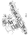
- Figure 2 is an exploded view of the connector of Figure 1;
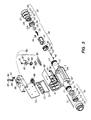
- Figure 3 is an exploded view of a connector of the invention suitable for connecting a heating cable to one elongate electrical component;
- Figure 4 is a perspective view with a partial cross-sectional view of the connection module of the invention with an installed heating cable;
- Figure 5 is a cross-sectional view along line V-V of Figure 4;
- Figures 6a and 6b are perspective views of braid capture means used in the connector of the invention, where Figure 6a shows the capture means before the heating cable is inserted and Figure 6b shows the capture means after insertion of the heating cable;
- Figure 7 is a perspective view with a partial cross-sectional view of the braid capture means shown in Figure 6;
- Figure 8 is a cross-sectional view of the braid capture means installed in the first inlet port of the shell;
- Figure 9 is an exploded view of a sealing assembly for use in the connector of the invention;
- Figure 10 is a perspective view of a connection module of the invention which contains a mirror for visual monitoring;
- Figures 11a and 11b are cross-sectional views along line XI-XI of Figure 10, where Figure 11a shows the connection means before an electrical connection is made and Figure 11b shows the connection means after an electrical connection is made; and
- Figures 12a and 12b are plan views of the surface of the connection module of Figure 10 in which Figure 12a shows reflection in the mirror before an electrical connection is made and Figure 12b shows the reflection in the mirror after an electrical connection is made.
-
- The invention is illustrated by the drawing in which Figure 1 shows a perspective view of a connector of the invention 1 in the demated configuration and Figure 2 is an exploded view of connector 1 of Figure 1 in a demated configuration. The connector 1 shown in Figures 1 and 2 is suitable for connecting a
first heating cable 40 in a powered tee configuration to three elongate electrical components: firstelongate component 46 which is a power cable, secondelongate component 47 which is a second heating cable, and thirdelongate component 48 which is a third heating cable.First shell member 3 is connected tosecond shell member 5 by means of hinges 7 and hingepin 9. Positioning pins 71 protrude throughlid gasket 74 and act to ensure proper positioning of thesecond shell member 5 andlid gasket 74 when mated. In the event that the connection means are incorrectly or incompletely assembled, the positioning pins 71 prevent thesecond shell member 5 from closing completely. To ensure tight closure of the shell members,lid snap lever 73 which is attached tolid bail 72 latches overlip 65 offirst shell member 3.Reentry indicators 66 in the form of plastic snaps are positioned at the corners oflid snap lever 73. An unsuccessful attempt to reopen the mated first andsecond shell members sheet 68 which acts to electrically insulate the connections.Attachment elements 67 are positioned along the sides offirst shell member 3 and allow cable ties or wire to pass through when making attachment to the pipe, conduit, or other substrate.Attachment elements 67 also function to receive snaps for a snap-on mounting bracket, if present. - Positioned within
first shell member 3 are afirst connection module 11 and asecond connection module 12. Both connection modules are made from a plastic which is transparent when molded.First connection module 11 contains a first connection means 80 and a second connection means 88, whilesecond connection module 12 contains a fourth connection means 90, a fifth connection means 91, a seventh connection means 93, and a eighth connection means 94. The first, second, fourth, fifth, seventh, and eighth connection means 80,88,90,91,93,94 are insulation displacement connectors (IDC) which are positioned on two U-shaped elements, the first, fourth, and seventh connection means 80,90,93 on one, and the second, fifth, and eighth connection means 88,91,94 on the second. As shown in exploded view in Figure 2, the IDC for first connection means 80 has a first piercingunit 83 positioned on top of a second piercingunit 84 and connected to the second piercing unit by means of ascrew 81. (Only the top ofscrew 81 is visible in Figure 1.) Awasher 82 and aconnection spring 86 are also part of the IDC, theconnection spring 86 serving to make an electrical connection between the IDC andpower bus 85. Also present on each of the first, second, fourth, fifth, seventh, and eighth connection means 80,88,90,91,93,94 is anindicator pin 87. Theindicator pin 87 is initially positioned so that it protrudes above the top surface of the connection module. After the heating cable and the elongate components are installed in the connector and each IDC is properly tightened, theindicator pin 87 becomes flush with the top surface of the connection module, indicating correct installation. Also present within thefirst connection module 11 when assembled is a third connection means which is first groundingelement 61. A groundingelement cross piece 63 connectsfirst grounding element 61 tosecond grounding element 62 which serves as the sixth connection means and is present. Theground pin 33,spring 39,spring 49,receptacle 31,spring 32, andclip 35 serve to connectsecond grounding element 62 to the grounding braid of thesecond heating cable 47. Similar elements are present forfirst heating cable 40 andthird heating cable 48. Strain relief means 95 is inserted into a slot in thesecond connection module 12 and a similar strain relief means is present in thefirst connection module 11. A firstgripping tooth 96 and a secondgripping tooth 97 are positioned on a hingedassembly 98 and can lock onto the heating cable when it is inserted into the connector. -
First inlet port 13 forfirst heating cable 40 andthird inlet port 15 for secondelongate component 47 are located adjacent to one another and on the opposite side offirst shell member 3 fromsecond inlet port 14 for firstelongate component 46 andfourth inlet port 16 for thirdelongate component 48. A sealing assembly is present to position and seal the heating cable and/or elongate components, the appropriate inlet port acts as the first component of the sealing assembly. To assist in making connection to the sealing assembly (half of which is indicated in exploded view by element 20), at least part of the outer surface ofsecond inlet port 15 has screw threads. These screw threads receive a threaded nut 21 (the third component of the assembly), which may comprise one or more pieces. As shown in Figures 1 and 2,nut 21 comprises a grippingportion 24. The second component of the sealing assembly is ahollow ring 22 from which protrudefingers 23. Also present is grommet 25 which is held in position byfingers 23.Second heating cable 47 passes through grommet opening 26 which is configured to allow heating cables of different sizes to enter.Grommet 25 provides sealing in two locations: around the insulating jacket of the heating cable (or other component) and by means ofgrommet flange 125 at the perimeter ofhollow ring 22.First mating element 27 onnut 21 mates with lockingelement 29 onfirst port 13 in order to ensure proper positioning on installation and to allow shipment of the connector with the parts held in place.Positioning elements 28 onring 22 mate with recesses 17 (and one opposite which is not shown) serve to keepgrommet 25 andring 22 from rotating asnut 21 is tightened. A similar sealing assembly is present forfirst heating cable 40 and may be present for the first elongate component or any other elongate components. - Also present in connector 1 is a
braid capture assembly 30 which fits insidethird inlet port 15 and serves to control the position of the metallic grounding braid and make an electrical connection to the braid.Spring 32, made for example from beryllium copper, is positioned withinmetal receptacle 31, as isbraid capture latch 34. Afterbraid capture clip 35 is positioned on the heating cable it is also installed withinmetal receptacle 31. Ametal ground pin 33 makes electrical connection tometal receptacle 31 by means ofspring 39 and tosecond grounding element 62 by means ofspring 49. Aninner grommet 36, withmembrane 37, is positioned betweenmetal receptacle 31 and the shell wall at the bottom ofthird inlet port 15 on thesecond connection module 12 and acts to prevent moisture from reaching the electrical connections.Membrane 37 is not open untilheating cable 47 is pushed through it. A similar braid capture assembly is present forfirst heating cable 40 as it is inserted intofirst inlet port 13, and forthird heating cable 48 which is inserted intofourth inlet port 16. - Figure 3 is an exploded view of a connector 1 similar to that of Figure 2 which is suitable for connecting a single heating cable to one elongate electrical component. Visible in Figure 3 are
supports 64 which allow the connector to stand above the substrate. - Figure 4 is a perspective view partially cut-away of
connection module 11 afterfirst heating cable 40 has been installed. First and secondelongate electrodes conductive polymer composition 43. An insulatingjacket 44 surrounds the conductive polymer. As shown in Figure 5, a cross-sectional view along line V-V of Figure 4, first and secondgripping teeth grip insulating jacket 44. First connection means 80, shown as an IDC, makes electrical contact tofirst electrode 41 by means of first and second piercingunits screw 81. Because the IDC is adequately tightened, the top ofindicator pin 87 is flush with the surface offirst connection module 11. - Figures 6a and 6b are perspective views which show in detail the
braid capture assembly 30 of the invention. As shown in Figure 6a, prior to insertion offirst heating cable 40 intometal receptacle 31,braid capture clip 35 is positioned over themetallic grounding braid 45 and the braid is pulled back over the clip.First heating cable 40 is then inserted intometal receptacle 31, with proper positioning occurring whenclip 35 is centered under spring 32 (see Figure 7). - Figure 7 is a perspective view partially cut-away of
braid capture assembly 30 as shown in Figure 6b following heating cable insertion. Visible in this figure arespring 32 which makes electrical connection to braid 45 andclip 35 to give a metal-metal-metal connection, andbraid capture latch 34, a locking mechanism which holdsfirst heating cable 40 properly positioned inmetal receptacle 31. In this view, for clarity, no braid is visible at the side ofclip 35, although in use, the braid generally is uniformly positioned around the clip.Metal ground pin 33 makes contact to braidreceptacle 31 throughspring 39 as well as tofirst grounding element 61 throughspring 49. - Figure 8 shows in greater detail in a cross-sectional view the
braid capture assembly 30 installed infirst inlet port 13 offirst shell member 3. Also shown isinner grommet 36, includingribs 38 positioned on the inner surface ofgrommet 36. These ribs act as flexible vanes to allow insertion of different size heating cables intogrommet 36. - Figure 9 shows an exploded view of a sealing
assembly 20, including the first component which isfirst inlet port 13, thesecond component 22 which is cylindrical ring having attachedfingers 23, the third component which is nut 21 (including gripping portion 24), and the fourth component which isgrommet 25.First mating element 27 used in conjunction with lockingelement 29 on the first inlet port, allows proper installation, positioning and shipping of the preassembled assembly. Positioningelement 28 mates withrecess 17 and restricts the second component andgrommet 25 from rotating when the sealing assembly is tightened. - Figure 10 is a perspective view of a
connection module 100 of the invention which contains a mirror for visual monitoring. The embodiment illustrated shows afirst mirror 101 positioned infirst cavity 108 for the first connection means 80 and asecond mirror 102 positioned insecond cavity 109 for the second connection means 88. Figures 11a and 11b are cross-sectional views of first connection means 80 taken along line Xl-Xl of Figure 10 before (Figure 11a) and after (Figure 11b) an electrical connection is made. Figures 12a and 12b are plan views of the surface of the connection module of Figure 10 in which Figure 12a shows the reflection infirst mirror 101 before an electrical connection is made and Figure 12b shows the reflection after an electrical connection is made.First mirror 101, shown here as ametal layer 104, is positioned onwall 105 offirst cavity 108, and is attached to wall 105 by adhesive or other means, if necessary.Wall 110 offirst cavity 108 is made from transparent plastic, although in other embodiments wall 110 need not be present or may be substantially opaque but have an opening or a window of transparent material. The angle C ofwall 105 with respect to the laminar surface of the connection module is shown as approximately 45°. Prior to insertion of theheating cable 40, thescrew threads 106 of first connection means 80 (shown here as an IDC) are visible in gap 107 (Figure 12a). After heatingcable 40 is inserted into first connection means 80, a screw driver 103 is used to tightenscrew 81 of the IDC, allowing electrical connection to be made by the first and second piercingunits gap 107, indicating a complete connection has been made.
(5) a sealing assembly suitable for sealing the first heating cable at the entry of the first inlet port, said assembly comprising
Claims (11)
- A connector (1) for connecting an end of a first elongate electrical heating cable (40) to an end of a first elongate electrical component (46), said first heating cable comprising first and second elongate electrodes (41,42), a plurality of resistive heating elements (43) connected in parallel between said electrodes, and an insulating jacket (44) surrounding said electrodes and heating elements, and said first electrical component comprising a first elongate member for connection to the first electrode and a second elongate member for connection to the second electrode, said connector comprisingcharacterised in that the first inlet port (13) is a hollow cylinder having an entry at one end and an outer surface at least a part of which comprises screw threads, and the connector further comprisesfirst and second shell members (3,5) which can be ina demated configuration, ora mated configuration in which the shell members (3,5) are in contact with each other and form a shell having (i) a first inlet port (13) for the first heating cable (40), and (ii) a second inlet port (14) for the first electrical component;securing means (7) for releasably maintaining the shell members (3,5) in the mated configuration;a first connection means (80) for connecting the first electrode (41) to the first elongate member of said first electrical component (46) within the shell; anda second connection means (88) for connecting the second electrode (42) to the second elongate member of said first electrical component (46) within the shell;said first and second connection means (80,88) being positioned within a first connection module (11) which fits within the shell when the first and second shell members are in the mated configuration.a sealing assembly (20) suitable for sealing the first heating cable (40) at the entry of the first inlet port (13), said assembly comprisinga hollow cylindrical ring (22) suitable for mating to the first inlet port and from which fingers (23) extend perpendicular to the plane of the ring,a nut (21) which can be screwed onto the threads of the first inlet port, anda grommet (25) which is held by the fingers and which seals around the first heating cable after installation,
- A connector according to claim 1 which further comprises:
a third connection means (89) for making an electrical connection within the shell between a first grounding element (61) and a third elongate member of said first electrical component (46). - A connector according to claim 1 or 2 wherein the first heating cable (40) further comprises a metallic grounding braid (45) surrounding said insulating jacket (44).
- A connector according to claim 1, 2, or 3 wherein the first inlet port (13) comprises a means for braid capture (30) which comprises a metal receptacle (31), a spring (32) which is attached to the metal receptacle and contacts and makes connection to the grounding braid, and a metal ground pin (33) which provides electrical connection between the metal receptacle and the grounding element, and preferably further comprises a clip (35) which makes physical contact to the braid and ensures contact of the braid with the spring.
- A connector according to any preceding claim wherein the first elongate electrical component (46) is a second elongate electrical heating cable comprising first and second elongate electrodes, a plurality of resistive heating elements connected in parallel between said electrodes, an insulating jacket surrounding said electrodes and heating elements, and (d) a metallic grounding braid surrounding said insulating jacket, or (ii) a grounded power cable.
- A connector according to any preceding claim connecting the electrical heating cable (40) to second and third electrical heating cables (47,48), each of which comprises first and second elongate electrodes, a plurality of resistive heating elements connected in parallel between said electrodes, an insulating jacket surrounding said electrodes and heating elements, and a metallic grounding braid surrounding said insulating jacket, the connector having first and second inlet ports at opposite ends of the shell, which connector further comprisesa third inlet port (15) for the second heating cable (47), said third port located at the same end of shell as the first port (13);a fourth inlet port (16) for the third heating cable (48), said fourth port located at the same end of the shell as the second port;a fourth connection means (90) for connecting within the shell the first electrode of the second heating cable to the first electrode of the third heating cable, the first electrode of the first heating cable, and the first elongate member of the first electrical component;a fifth connection means (91) for connecting within the shell the second electrode of the second heating cable to the second electrode of the third heating cable, and the second electrode of the second heating cable, and the second elongate member of the first electrical component; anda sixth connection means (92) for making an electrical connection between a second grounding element (62) and the grounding braid of the second heating cable, the grounding braid of the third heating cable, and the third connection means (89);said fourth and fifth connection means being positioned within a second connection module (12) which fits within the shell adjacent to the first connection module (11) when the first and second shell members (3,5) are in the mated configuration.
- A connector according to any one of the preceding claims wherein the first and second connection means (80,88) comprise insulation displacement connectors.
- A connector according to any one of the preceding claims wherein the first connection module (11) is transparent.
- A connector according to any one of the preceding claims wherein the fingers (23) of the cylindrical ring (22) of the sealing assembly (20) are composed of a material which is a polymeric composition and has a flexural modulus of at most 3,5 Kg/m2 (500,000 psi) and an ultimate elongation of at least 100%.
- A connector according to any one of the preceding claims which further comprises means for strain relief (95).
- A connector according to claim 8 or claims 9 or 10 in combination with claim 8 which further comprises a mirror (101) which is inserted in the module, and is positioned so that the connection means can be observed from outside the module.
Priority Applications (1)
| Application Number | Priority Date | Filing Date | Title |
|---|---|---|---|
| EP00108453A EP1020960B1 (en) | 1994-10-25 | 1995-10-23 | Sealing assembly for socket connectors |
Applications Claiming Priority (3)
| Application Number | Priority Date | Filing Date | Title |
|---|---|---|---|
| US328644 | 1989-03-28 | ||
| US08/328,644 US5756972A (en) | 1994-10-25 | 1994-10-25 | Hinged connector for heating cables of various sizes |
| PCT/US1995/013920 WO1996013080A2 (en) | 1994-10-25 | 1995-10-23 | Connector for elongate cable |
Related Child Applications (1)
| Application Number | Title | Priority Date | Filing Date |
|---|---|---|---|
| EP00108453A Division EP1020960B1 (en) | 1994-10-25 | 1995-10-23 | Sealing assembly for socket connectors |
Publications (2)
| Publication Number | Publication Date |
|---|---|
| EP0788671A2 EP0788671A2 (en) | 1997-08-13 |
| EP0788671B1 true EP0788671B1 (en) | 2000-12-27 |
Family
ID=23281818
Family Applications (2)
| Application Number | Title | Priority Date | Filing Date |
|---|---|---|---|
| EP00108453A Expired - Lifetime EP1020960B1 (en) | 1994-10-25 | 1995-10-23 | Sealing assembly for socket connectors |
| EP95938942A Expired - Lifetime EP0788671B1 (en) | 1994-10-25 | 1995-10-23 | Connector for elongate cable |
Family Applications Before (1)
| Application Number | Title | Priority Date | Filing Date |
|---|---|---|---|
| EP00108453A Expired - Lifetime EP1020960B1 (en) | 1994-10-25 | 1995-10-23 | Sealing assembly for socket connectors |
Country Status (15)
| Country | Link |
|---|---|
| US (1) | US5756972A (en) |
| EP (2) | EP1020960B1 (en) |
| JP (1) | JP3692142B2 (en) |
| KR (1) | KR100383030B1 (en) |
| CN (1) | CN1086850C (en) |
| AT (2) | ATE211864T1 (en) |
| AU (1) | AU701545B2 (en) |
| BR (1) | BR9509482A (en) |
| CA (1) | CA2203508C (en) |
| DE (2) | DE69525087T2 (en) |
| FI (1) | FI971751A (en) |
| MX (1) | MX9702972A (en) |
| NO (1) | NO320164B1 (en) |
| NZ (1) | NZ296358A (en) |
| WO (1) | WO1996013080A2 (en) |
Families Citing this family (50)
| Publication number | Priority date | Publication date | Assignee | Title |
|---|---|---|---|---|
| JP3300259B2 (en) * | 1997-06-06 | 2002-07-08 | 矢崎総業株式会社 | Insulation terminal and connection method between insulation terminal and electric wire |
| EP0998768A1 (en) * | 1997-07-25 | 2000-05-10 | Eric Polgar | Device for connecting flattened electric cables, whether heating or not, comprising two conductors embedded in a polymer |
| EP1121728B1 (en) | 1998-10-15 | 2005-11-09 | TYCO Electronics Corporation | Connector for electrical cable |
| ATE231656T1 (en) * | 1998-11-11 | 2003-02-15 | Pc Electric Gmbh | CABLE CLAMP |
| EP1009082B1 (en) * | 1998-12-10 | 2002-06-26 | Nexans | Screen connection for mechanico retractable products |
| US6358103B1 (en) * | 1999-08-02 | 2002-03-19 | Swenco Products, Inc. | No-crimp electrical connector side-by-side type |
| US6494753B1 (en) * | 1999-08-02 | 2002-12-17 | Swenco Products, Inc. | No-crimp electrical connector side-by-side type and method |
| FR2820888B1 (en) * | 2001-02-09 | 2004-02-06 | Orientation Production | WATERPROOF CONNECTOR FOR ELECTRICAL CABLES |
| GB0104098D0 (en) * | 2001-02-20 | 2001-04-04 | Hawke Cable Glands Ltd | Cable gland assemblies |
| DE20106745U1 (en) * | 2001-04-19 | 2002-08-29 | Bosch Gmbh Robert | Small coupling connector, especially for a planar broadband lamda probe with loss protection for single wire seals |
| KR100411426B1 (en) * | 2001-08-20 | 2003-12-18 | 현대자동차주식회사 | Hinge |
| US6706970B2 (en) * | 2002-01-04 | 2004-03-16 | Tyco Electronics Corporation | Strain relief for electrical cable |
| DE10219019B3 (en) * | 2002-04-27 | 2004-01-15 | Bartec Componenten Und Systeme Gmbh | Device for connecting two electrical cables |
| US6825448B2 (en) * | 2003-05-01 | 2004-11-30 | Applied Materials, Inc. | Low residual-stress brazed terminal for heater |
| US7134911B2 (en) * | 2005-01-12 | 2006-11-14 | Tyco Electronics Corporation | Keyed electrical connector with sealing boot |
| US7170010B1 (en) * | 2005-07-18 | 2007-01-30 | Thomas & Betts International, Inc. | Protective cover and system for electrical enclosures |
| US8809751B2 (en) * | 2005-08-09 | 2014-08-19 | Watlow Electric Manufacturing Company | Modular heater system |
| US7964826B2 (en) * | 2005-08-09 | 2011-06-21 | Watlow Electric Manufacturing Company | Modular heater systems |
| US7232955B1 (en) * | 2005-12-08 | 2007-06-19 | General Electric Company | Cable seals and methods of assembly |
| CA2616498C (en) * | 2007-12-28 | 2015-06-23 | Drexan Corporation | Multipurpose cable connector |
| US7942031B2 (en) * | 2008-03-13 | 2011-05-17 | Rocky Research | Sensor mount assembly |
| DE102009006383A1 (en) * | 2009-01-28 | 2010-09-16 | Festo Ag & Co. Kg | Two-piece cable-strain relief device for fixing cables in region of e.g. electrical connections, has teeth rows arranged at distance from each other, where tooth of one of rows are displaced at half teeth row distance to tooth of other row |
| JP2012519388A (en) | 2009-03-03 | 2012-08-23 | アーベーベー・テヒノロギー・アーゲー | Electrical module with fixing device |
| JP5578980B2 (en) * | 2009-11-06 | 2014-08-27 | 矢崎総業株式会社 | Connector and connector manufacturing method |
| US8341838B2 (en) * | 2010-11-22 | 2013-01-01 | Andrew Llc | Method of installing a coaxial cable into an electrical connector |
| US8657626B2 (en) * | 2010-12-02 | 2014-02-25 | Thomas & Betts International, Inc. | Cable connector with retaining element |
| US8845361B2 (en) * | 2011-11-08 | 2014-09-30 | Thomas & Betts International Llc | Explosion-proof electrical fitting |
| EP2867964B1 (en) | 2012-07-02 | 2018-06-06 | CommScope Connectivity Belgium BVBA | Seal actuator with actuation level indicator |
| KR102184478B1 (en) | 2012-07-02 | 2020-12-01 | 타이코 일렉트로닉스 레이켐 비브이비에이 | Cable sealing unit with multiple sealing modules |
| US20140312029A1 (en) * | 2013-03-25 | 2014-10-23 | Rosalie Berger | Flexible, Low-Profile Heating Cable |
| US9425545B2 (en) * | 2013-11-13 | 2016-08-23 | Heath Monroe Bedal | Electrical wire connector |
| CN104167707A (en) * | 2014-07-22 | 2014-11-26 | 苏州边桐传感科技有限公司 | Simple amphibious cable joint |
| US9685730B2 (en) | 2014-09-12 | 2017-06-20 | Steelcase Inc. | Floor power distribution system |
| US10557584B2 (en) | 2015-12-16 | 2020-02-11 | Watlow Electric Manufacturing Company | Modular heater systems |
| CN106229934B (en) * | 2016-08-19 | 2019-01-25 | 杭州洪鑫电力科技有限公司 | A kind of cable channel is interior to be blocked |
| PL3396798T3 (en) * | 2017-04-25 | 2021-10-18 | Corning Research & Development Corporation | Sealing body for telecommunication cables |
| DE102017110496B3 (en) * | 2017-05-15 | 2018-09-20 | Lisa Dräxlmaier GmbH | COMPENSATION ELEMENT FOR A CONNECTOR AND CONNECTOR |
| EP3410543B1 (en) * | 2017-05-31 | 2023-04-19 | ITT Manufacturing Enterprises LLC | Splice connector assemblies |
| US9936540B1 (en) | 2017-06-28 | 2018-04-03 | Chromalox, Inc. | Snap fit accessory for heat trace cable |
| US10955096B1 (en) * | 2018-01-23 | 2021-03-23 | The Light Source, Inc. | Electrical connector pipe adapted for structural applications |
| JP6763896B2 (en) * | 2018-02-15 | 2020-09-30 | 株式会社オートネットワーク技術研究所 | connector |
| CN111903002B (en) * | 2018-02-19 | 2022-11-04 | 沃特洛电气制造公司 | Compact robust connector assembly for high voltage electric heater |
| CN108899860B (en) * | 2018-09-04 | 2024-03-29 | 沈阳北方艾克电缆有限公司 | Fireproof cable branch box |
| US11604218B2 (en) | 2018-09-10 | 2023-03-14 | 3M Innovative Properties Company | Electrical power cable monitoring device including partial discharge sensor |
| WO2020055662A1 (en) * | 2018-09-10 | 2020-03-19 | 3M Innovative Properties Company | Support structure for cable and cable accessory condition monitoring devices |
| EP3850380A1 (en) | 2018-09-10 | 2021-07-21 | 3M Innovative Properties Company | Electrical power cable monitoring device using low side electrode and earth ground separation |
| EP3981052A4 (en) * | 2019-06-05 | 2023-10-11 | Tyco Fire Products LP | Clamping connector |
| CN111769379B (en) * | 2020-06-30 | 2021-09-24 | 国网安徽省电力有限公司马鞍山供电公司 | Grounding box for power distribution network construction |
| US11658436B2 (en) * | 2020-07-01 | 2023-05-23 | Commscope Technologies Llc | Power cable connectors and assemblies |
| CN112804789A (en) * | 2021-02-03 | 2021-05-14 | 赛尔富电子有限公司 | LED power supply |
Family Cites Families (110)
| Publication number | Priority date | Publication date | Assignee | Title |
|---|---|---|---|---|
| US962589A (en) * | 1909-08-21 | 1910-06-28 | Louis Hengerer | Receptacle or socket for electric lamps. |
| US2000318A (en) * | 1933-05-22 | 1935-05-07 | James H Cannon | Cord connecter |
| US2870420A (en) * | 1955-04-05 | 1959-01-20 | American Phenolic Corp | Electrical connector for coaxial cable |
| US3064227A (en) * | 1957-09-17 | 1962-11-13 | Sams Martin | Electrical terminal |
| US3020518A (en) * | 1959-03-05 | 1962-02-06 | Camping Ralph | Solderless electrical connectors |
| US3076169A (en) * | 1959-04-21 | 1963-01-29 | Kenneth L Blaisdell | Coaxial cable connectors |
| US3110756A (en) * | 1960-11-22 | 1963-11-12 | Thompson Ramo Wooldridge Inc | Coaxial cable connector |
| US3104145A (en) * | 1961-01-23 | 1963-09-17 | Gremar Mfg Co Inc | Coaxial connectors |
| US3129048A (en) * | 1961-06-15 | 1964-04-14 | Frederick J Broch | Electrical connector |
| US3141718A (en) * | 1962-01-03 | 1964-07-21 | Te Ind Inc | Solderless right angle plug connector |
| US3227991A (en) * | 1962-12-20 | 1966-01-04 | Siemon Co | Electrical connector |
| US3408616A (en) * | 1966-04-21 | 1968-10-29 | Acad Electrical Prod Corp | Insulation piercing electrical connectors |
| US3414867A (en) * | 1967-04-13 | 1968-12-03 | Electro Connective Systems Inc | Termination of cable |
| AT289231B (en) * | 1968-02-20 | 1971-04-13 | Kabel Metallwerke Ghh | Method for the electrical connection of two electrical communication cables |
| US3688246A (en) * | 1968-06-06 | 1972-08-29 | John A Toedtman | Electrical connector with insulation-piercing contact pins |
| US3760331A (en) * | 1969-03-14 | 1973-09-18 | Amp Inc | Electrical connecting device for insulated wires |
| US3603912A (en) * | 1969-08-25 | 1971-09-07 | Thomas & Betts Corp | Raceway terminator |
| US3717840A (en) * | 1971-02-03 | 1973-02-20 | Inc Nv | Electrical circuit connection |
| US3739076A (en) * | 1972-04-17 | 1973-06-12 | L Schwartz | Electrical cable terminating and grounding connector |
| US3764959A (en) * | 1972-07-18 | 1973-10-09 | Astrolab | Universal coaxial cable connector |
| US3861029A (en) * | 1972-09-08 | 1975-01-21 | Raychem Corp | Method of making heater cable |
| US3858144A (en) * | 1972-12-29 | 1974-12-31 | Raychem Corp | Voltage stress-resistant conductive articles |
| US4017715A (en) * | 1975-08-04 | 1977-04-12 | Raychem Corporation | Temperature overshoot heater |
| US3879099A (en) * | 1973-09-04 | 1975-04-22 | Amp Inc | Flat fexible cable connector assembly including insulation piercing contacts |
| US3936126A (en) * | 1973-12-07 | 1976-02-03 | Dart Industries Inc. | Electrical connector |
| US3916149A (en) * | 1974-02-20 | 1975-10-28 | Electro Therm | Electric heater element connection assembly |
| GB1512626A (en) * | 1974-05-03 | 1978-06-01 | Raychem Ltd | Method of terminating electric cable |
| GB1521460A (en) * | 1974-08-30 | 1978-08-16 | Raychem Corp | Self-limiting electrically resistive article and process for its manufacture |
| US3976351A (en) * | 1974-12-12 | 1976-08-24 | Mark Products, Inc. | Electrical connector |
| CA1072649A (en) * | 1976-01-07 | 1980-02-26 | Robert H. Frantz | Insulated electrical connector housing |
| GB1543678A (en) * | 1976-07-16 | 1979-04-04 | Lapp Kg U | Clamping device for cables leads hoses or the like |
| US4426339B1 (en) * | 1976-12-13 | 1993-12-21 | Raychem Corp. | Method of making electrical devices comprising conductive polymer compositions |
| US4103984A (en) * | 1977-01-27 | 1978-08-01 | Amp Incorporated | Insulation displacing pin connector |
| US4148539A (en) * | 1977-04-29 | 1979-04-10 | Western Electric Company, Incorporated | Modular plug having superior dielectric strength for terminating cords |
| US4114974A (en) * | 1977-08-29 | 1978-09-19 | General Electric Company | Dust shield for cap and connector |
| DE2835832C2 (en) | 1978-08-16 | 1982-06-03 | Dietrich 7778 Markdorf Grünau | Cable entry |
| US4243290A (en) * | 1978-10-30 | 1981-01-06 | Williams Robert A | Shield termination means for electrical connector |
| US4242573A (en) * | 1979-01-24 | 1980-12-30 | Raychem Corporation | Water immersible heater |
| DE2902536C2 (en) * | 1979-01-24 | 1980-12-18 | C. A. Weidmueller Kg, 4930 Detmold | Terminal block |
| DE2937228C2 (en) | 1979-09-14 | 1982-09-16 | Ernst Pflitsch & Co Gebr. Pflitsch GmbH, 5609 Hückeswagen | Sealing nipple |
| US4334351A (en) * | 1980-05-19 | 1982-06-15 | Raychem Corporation | Novel PTC devices and their preparation |
| US4341430A (en) * | 1980-11-05 | 1982-07-27 | Amp Incorporated | Flat cable connector |
| FR2498821A1 (en) * | 1981-01-23 | 1982-07-30 | Legrand Sa | ELECTRICAL CONNECTOR FOR INSULATED DRIVER |
| US4413872A (en) * | 1981-05-11 | 1983-11-08 | Amp Incorporated | Preloaded electrical connector |
| US4397516A (en) * | 1981-05-26 | 1983-08-09 | The Bendix Corporation | Cable termination apparatus |
| US4574188A (en) * | 1982-04-16 | 1986-03-04 | Raychem Corporation | Elongate electrical assemblies |
| US4459473A (en) * | 1982-05-21 | 1984-07-10 | Raychem Corporation | Self-regulating heaters |
| US4864725A (en) * | 1982-10-12 | 1989-09-12 | Raychem Corporation | Electrical connector and method of splicing wires |
| US4600261A (en) * | 1982-10-12 | 1986-07-15 | Raychem Corporation | Apparatus and method for protection of electrical contacts |
| US4588249A (en) * | 1982-11-03 | 1986-05-13 | Amp Incorporated | Coaxial cable tap connector |
| US4583811A (en) * | 1983-03-29 | 1986-04-22 | Raychem Corporation | Mechanical coupling assembly for a coaxial cable and method of using same |
| US4865905A (en) * | 1983-06-23 | 1989-09-12 | Raychem Corporation | Article for protection of a substrate |
| US4690831A (en) * | 1983-06-23 | 1987-09-01 | Raychem Corp. | Protective article |
| US4623753A (en) * | 1983-10-31 | 1986-11-18 | Amp Incorporated | Watertight junction box |
| US4525000A (en) * | 1984-02-17 | 1985-06-25 | General Signal Corporation | Cable fitting with variable inner diameter grommet assembly |
| DE3420021A1 (en) | 1984-05-29 | 1985-12-05 | Richard Hirschmann Radiotechnisches Werk, 7300 Esslingen | Cable grip |
| US4602840A (en) * | 1984-06-01 | 1986-07-29 | Harvey Hubbell Incorporated | Under-carpet connection system |
| US4541680A (en) * | 1984-08-02 | 1985-09-17 | Brand-Rex Company | Electrical connector assembly |
| US4566745A (en) * | 1984-08-20 | 1986-01-28 | Cooper Industries, Inc. | Connector assembly |
| US4995830A (en) * | 1984-10-02 | 1991-02-26 | Ira Eckhaus | Electrical wire connectors |
| US4744769A (en) * | 1984-12-20 | 1988-05-17 | Amp Incorporated | Closed loop connector |
| US4640569A (en) * | 1985-03-27 | 1987-02-03 | Amp Incorporated | Adaptor for coupling a cable to a connector |
| US4652071A (en) * | 1985-04-08 | 1987-03-24 | Northern Telecom Limited | Cable terminal connector with insulation displacing terminals |
| US4777063A (en) * | 1985-05-02 | 1988-10-11 | Raychem Corporation | Curable organopolysiloxane composition |
| FR2584538B1 (en) * | 1985-07-02 | 1987-09-25 | Alsthom Cgee | SELF-INSULATING BUILT-IN CONNECTION ARRANGEMENT FOR ELECTRICAL EQUIPMENT AND CONNECTION TOOL FOR SUCH AN ARRANGEMENT |
| US4637639A (en) * | 1985-07-22 | 1987-01-20 | Harvey Hubbell Incorporated | Non-metallic liquid-tight conduit engaging connector |
| US4629274A (en) * | 1985-10-01 | 1986-12-16 | Pollock Henry J | Electrical connector |
| US4716183A (en) * | 1985-11-22 | 1987-12-29 | Raychem Corp. | Styrene-diene block copolymer compositions |
| US4684195A (en) * | 1985-12-19 | 1987-08-04 | American Telephone And Telegraph Company, At&T Bell Laboratories | Solderless electrical connector |
| DE3607451A1 (en) * | 1986-03-07 | 1987-09-17 | Rose Walter Gmbh & Co Kg | Device for fixing cables in cable entry stubs |
| US4789759A (en) * | 1986-03-25 | 1988-12-06 | Amp Incorporated | Assembly for an electrical cable providing strain relief and a water-tight seal |
| US4733015A (en) * | 1986-05-05 | 1988-03-22 | Emerson Electric Co. | Termination assembly |
| IT1195882B (en) * | 1986-07-29 | 1988-10-27 | Antonio Ferruccio | PREFABRICATED COMPOSITE ELEMENT FOR THE FORMATION OF BREAKFAST BARRIERS |
| US4897046A (en) * | 1986-10-03 | 1990-01-30 | Minnesota Mining And Manufacturing Company | Shielded connector system for coaxial cables |
| US4701138A (en) * | 1986-12-18 | 1987-10-20 | Phoenix Terminal Blocks Inc. | Solderless electrical connector |
| ES1004786Y (en) * | 1986-12-22 | 1989-04-01 | Amp Incorporated | AN ELECTRICAL CONNECTOR. |
| JPH0530307Y2 (en) * | 1987-02-12 | 1993-08-03 | ||
| US4761146A (en) * | 1987-04-22 | 1988-08-02 | Spm Instrument Inc. | Coaxial cable connector assembly and method for making |
| US5069636A (en) * | 1987-07-07 | 1991-12-03 | Raychem Corporation | Terminal block and adapter |
| US5149736A (en) * | 1987-07-13 | 1992-09-22 | Raychem Corporation | Heat resistant gel compositions |
| US4790765A (en) * | 1987-10-05 | 1988-12-13 | Hubbell Incorporated | Connector shunt structure |
| US4759725A (en) * | 1987-10-26 | 1988-07-26 | Don Finch | Electrical wiring fixture |
| US4793822A (en) * | 1987-10-28 | 1988-12-27 | Amp Incorporated | Screw slot connector |
| CA1298369C (en) * | 1987-11-06 | 1992-03-31 | George Debortoli | Insulation displacement members and electrical connectors |
| DE8715349U1 (en) * | 1987-11-19 | 1988-01-21 | Preh, Elektrofeinmechanische Werke Jakob Preh Nachf. Gmbh & Co, 8740 Bad Neustadt, De | |
| US4846721A (en) * | 1988-02-17 | 1989-07-11 | Raychem Corporation | Telecommunications terminal block |
| GB8804134D0 (en) | 1988-02-23 | 1988-03-23 | Raychem Pontoise Sa | Cable connecting module |
| US4929189A (en) * | 1988-04-13 | 1990-05-29 | Hosiden Electronics Co., Ltd. | Connector with locking mechanism |
| US4971573A (en) * | 1988-09-19 | 1990-11-20 | Raychem Corporation | Electrical connection device providing integral strain relief |
| US4883945A (en) * | 1988-12-08 | 1989-11-28 | Raychem Corporation | Connector for electrical heater |
| US4900068A (en) * | 1988-12-19 | 1990-02-13 | Heyco Molded Products, Inc. | Liquid tight connector for flexible non-metallic conduit and flexible non-metallic tubing |
| DE3903354C1 (en) * | 1989-02-04 | 1990-02-01 | Anton Hummel Gmbh Metallwarenfabrik, 7808 Waldkirch, De | |
| WO1990010035A1 (en) * | 1989-03-01 | 1990-09-07 | Raychem Corporation | Method of curing organopolysiloxane compositions and compositions and articles therefrom |
| US5111032A (en) * | 1989-03-13 | 1992-05-05 | Raychem Corporation | Method of making an electrical device comprising a conductive polymer |
| US4963104A (en) * | 1989-05-01 | 1990-10-16 | Spark Innovations, Inc. | Shielded connector assembly |
| US4952174A (en) * | 1989-05-15 | 1990-08-28 | Raychem Corporation | Coaxial cable connector |
| US5127853A (en) * | 1989-11-08 | 1992-07-07 | Raychem Corporation | Feedthrough coaxial cable connector |
| US5041012A (en) * | 1989-06-27 | 1991-08-20 | Bardes Corporation, Ilsco Division | Insulation piercing electrical clamp connector |
| CH680958A5 (en) * | 1989-11-08 | 1992-12-15 | Domotec Ag | |
| JPH088542Y2 (en) * | 1989-12-19 | 1996-03-06 | 日本航空電子工業株式会社 | Connector with complete mating detection mechanism |
| US5104930A (en) * | 1990-02-27 | 1992-04-14 | Raychem Corporation | Polyurea gel compositions and articles therefrom |
| US5151053A (en) | 1990-03-05 | 1992-09-29 | Yazaki Corporation | Electrical connector for shielding cable |
| US5051541A (en) * | 1990-03-23 | 1991-09-24 | Thomas & Betts Corporation | Plastic electrical connector for liquidtight conduit |
| US5102351A (en) * | 1990-11-29 | 1992-04-07 | The United States Of America As Represented By The Secretary Of The Air Force | Shielded electric cable and harness with strain relief |
| US5088934A (en) * | 1991-02-20 | 1992-02-18 | Chian Chyun Enterprise Co. Ltd. | Electrical terminal |
| DE4108677A1 (en) | 1991-03-16 | 1992-09-17 | Reiss Int Gmbh | Feedthrough cable connection sealed against dust and moisture - has central portion which is ruptured and turned back to form tight seal around inserted cable |
| US5116230A (en) * | 1991-04-09 | 1992-05-26 | Molex Incorporated | Coaxial cable connector |
| US5145388A (en) * | 1991-05-31 | 1992-09-08 | Amp Incorporated | Enclosure for crossconnect terminal block |
| GB2260864B (en) | 1991-10-24 | 1995-09-13 | Bill Moule & Sons Ltd | Electrical connector |
| US5378174A (en) | 1993-03-18 | 1995-01-03 | The Whitaker Corporation | Enclosure for variety of terminal blocks |
-
1994
- 1994-10-25 US US08/328,644 patent/US5756972A/en not_active Expired - Lifetime
-
1995
- 1995-10-23 NZ NZ296358A patent/NZ296358A/en not_active IP Right Cessation
- 1995-10-23 MX MX9702972A patent/MX9702972A/en not_active Application Discontinuation
- 1995-10-23 CN CN95195869A patent/CN1086850C/en not_active Expired - Fee Related
- 1995-10-23 AT AT00108453T patent/ATE211864T1/en not_active IP Right Cessation
- 1995-10-23 AU AU40140/95A patent/AU701545B2/en not_active Ceased
- 1995-10-23 CA CA002203508A patent/CA2203508C/en not_active Expired - Fee Related
- 1995-10-23 EP EP00108453A patent/EP1020960B1/en not_active Expired - Lifetime
- 1995-10-23 BR BR9509482A patent/BR9509482A/en not_active IP Right Cessation
- 1995-10-23 WO PCT/US1995/013920 patent/WO1996013080A2/en active IP Right Grant
- 1995-10-23 JP JP51414496A patent/JP3692142B2/en not_active Expired - Fee Related
- 1995-10-23 AT AT95938942T patent/ATE198389T1/en active
- 1995-10-23 DE DE69525087T patent/DE69525087T2/en not_active Expired - Lifetime
- 1995-10-23 DE DE69519745T patent/DE69519745T2/en not_active Expired - Lifetime
- 1995-10-23 KR KR1019970702699A patent/KR100383030B1/en not_active IP Right Cessation
- 1995-10-23 EP EP95938942A patent/EP0788671B1/en not_active Expired - Lifetime
-
1997
- 1997-04-24 FI FI971751A patent/FI971751A/en not_active Application Discontinuation
- 1997-04-24 NO NO19971891A patent/NO320164B1/en not_active IP Right Cessation
Also Published As
| Publication number | Publication date |
|---|---|
| DE69525087D1 (en) | 2002-02-28 |
| AU4014095A (en) | 1996-05-15 |
| EP0788671A2 (en) | 1997-08-13 |
| KR970707610A (en) | 1997-12-01 |
| CN1086850C (en) | 2002-06-26 |
| DE69525087T2 (en) | 2002-09-26 |
| DE69519745T2 (en) | 2001-08-02 |
| DE69519745D1 (en) | 2001-02-01 |
| NO971891D0 (en) | 1997-04-24 |
| EP1020960B1 (en) | 2002-01-09 |
| WO1996013080A2 (en) | 1996-05-02 |
| JPH10507865A (en) | 1998-07-28 |
| AU701545B2 (en) | 1999-01-28 |
| FI971751A0 (en) | 1997-04-24 |
| NZ296358A (en) | 1998-06-26 |
| EP1020960A3 (en) | 2000-08-09 |
| ATE211864T1 (en) | 2002-01-15 |
| BR9509482A (en) | 1997-10-14 |
| CA2203508A1 (en) | 1996-05-02 |
| CA2203508C (en) | 2005-01-11 |
| NO320164B1 (en) | 2005-11-07 |
| NO971891L (en) | 1997-04-24 |
| MX9702972A (en) | 1997-06-28 |
| JP3692142B2 (en) | 2005-09-07 |
| WO1996013080A3 (en) | 1996-07-18 |
| FI971751A (en) | 1997-04-24 |
| KR100383030B1 (en) | 2003-07-16 |
| US5756972A (en) | 1998-05-26 |
| ATE198389T1 (en) | 2001-01-15 |
| EP1020960A2 (en) | 2000-07-19 |
| CN1161763A (en) | 1997-10-08 |
Similar Documents
| Publication | Publication Date | Title |
|---|---|---|
| EP0788671B1 (en) | Connector for elongate cable | |
| MXPA97002972A (en) | Cable connector alarg | |
| CA2212173C (en) | Sealing device | |
| US4877943A (en) | Sealing device for elongate heater | |
| US5718600A (en) | Electrical plug | |
| US4312121A (en) | Connection system for heater strips | |
| EP1050942B1 (en) | Sealing device | |
| JP4044289B2 (en) | Electrical cable connector | |
| EP0451191B1 (en) | Connector for electrical heater | |
| CA2230591C (en) | Sealing device | |
| MXPA97005851A (en) | Seal device |
Legal Events
| Date | Code | Title | Description |
|---|---|---|---|
| PUAI | Public reference made under article 153(3) epc to a published international application that has entered the european phase |
Free format text: ORIGINAL CODE: 0009012 |
|
| 17P | Request for examination filed |
Effective date: 19970426 |
|
| AK | Designated contracting states |
Kind code of ref document: A2 Designated state(s): AT BE CH DE DK ES FR GB IE IT LI NL PT SE |
|
| 17Q | First examination report despatched |
Effective date: 19970807 |
|
| GRAG | Despatch of communication of intention to grant |
Free format text: ORIGINAL CODE: EPIDOS AGRA |
|
| 17Q | First examination report despatched |
Effective date: 19970807 |
|
| RAP1 | Party data changed (applicant data changed or rights of an application transferred) |
Owner name: TYCO ELECTRONICS CORPORATION |
|
| GRAG | Despatch of communication of intention to grant |
Free format text: ORIGINAL CODE: EPIDOS AGRA |
|
| GRAH | Despatch of communication of intention to grant a patent |
Free format text: ORIGINAL CODE: EPIDOS IGRA |
|
| GRAH | Despatch of communication of intention to grant a patent |
Free format text: ORIGINAL CODE: EPIDOS IGRA |
|
| GRAA | (expected) grant |
Free format text: ORIGINAL CODE: 0009210 |
|
| AK | Designated contracting states |
Kind code of ref document: B1 Designated state(s): AT BE CH DE DK ES FR GB IE IT LI NL PT SE |
|
| PG25 | Lapsed in a contracting state [announced via postgrant information from national office to epo] |
Ref country code: SE Free format text: LAPSE BECAUSE OF FAILURE TO SUBMIT A TRANSLATION OF THE DESCRIPTION OR TO PAY THE FEE WITHIN THE PRESCRIBED TIME-LIMIT Effective date: 20001227 Ref country code: NL Free format text: LAPSE BECAUSE OF FAILURE TO SUBMIT A TRANSLATION OF THE DESCRIPTION OR TO PAY THE FEE WITHIN THE PRESCRIBED TIME-LIMIT Effective date: 20001227 Ref country code: IT Free format text: LAPSE BECAUSE OF FAILURE TO SUBMIT A TRANSLATION OF THE DESCRIPTION OR TO PAY THE FEE WITHIN THE PRESCRIBED TIME-LIMIT;WARNING: LAPSES OF ITALIAN PATENTS WITH EFFECTIVE DATE BEFORE 2007 MAY HAVE OCCURRED AT ANY TIME BEFORE 2007. THE CORRECT EFFECTIVE DATE MAY BE DIFFERENT FROM THE ONE RECORDED. Effective date: 20001227 Ref country code: ES Free format text: THE PATENT HAS BEEN ANNULLED BY A DECISION OF A NATIONAL AUTHORITY Effective date: 20001227 Ref country code: BE Free format text: LAPSE BECAUSE OF FAILURE TO SUBMIT A TRANSLATION OF THE DESCRIPTION OR TO PAY THE FEE WITHIN THE PRESCRIBED TIME-LIMIT Effective date: 20001227 Ref country code: AT Free format text: LAPSE BECAUSE OF FAILURE TO SUBMIT A TRANSLATION OF THE DESCRIPTION OR TO PAY THE FEE WITHIN THE PRESCRIBED TIME-LIMIT Effective date: 20001227 |
|
| REF | Corresponds to: |
Ref document number: 198389 Country of ref document: AT Date of ref document: 20010115 Kind code of ref document: T |
|
| REG | Reference to a national code |
Ref country code: CH Ref legal event code: NV Representative=s name: KIRKER & CIE SA Ref country code: CH Ref legal event code: EP |
|
| REF | Corresponds to: |
Ref document number: 69519745 Country of ref document: DE Date of ref document: 20010201 |
|
| REG | Reference to a national code |
Ref country code: IE Ref legal event code: FG4D |
|
| ET | Fr: translation filed | ||
| PG25 | Lapsed in a contracting state [announced via postgrant information from national office to epo] |
Ref country code: PT Free format text: LAPSE BECAUSE OF FAILURE TO SUBMIT A TRANSLATION OF THE DESCRIPTION OR TO PAY THE FEE WITHIN THE PRESCRIBED TIME-LIMIT Effective date: 20010327 Ref country code: DK Free format text: LAPSE BECAUSE OF FAILURE TO SUBMIT A TRANSLATION OF THE DESCRIPTION OR TO PAY THE FEE WITHIN THE PRESCRIBED TIME-LIMIT Effective date: 20010327 |
|
| NLV1 | Nl: lapsed or annulled due to failure to fulfill the requirements of art. 29p and 29m of the patents act | ||
| PG25 | Lapsed in a contracting state [announced via postgrant information from national office to epo] |
Ref country code: IE Free format text: LAPSE BECAUSE OF FAILURE TO SUBMIT A TRANSLATION OF THE DESCRIPTION OR TO PAY THE FEE WITHIN THE PRESCRIBED TIME-LIMIT Effective date: 20011023 |
|
| PLBE | No opposition filed within time limit |
Free format text: ORIGINAL CODE: 0009261 |
|
| STAA | Information on the status of an ep patent application or granted ep patent |
Free format text: STATUS: NO OPPOSITION FILED WITHIN TIME LIMIT |
|
| 26N | No opposition filed | ||
| REG | Reference to a national code |
Ref country code: GB Ref legal event code: IF02 |
|
| REG | Reference to a national code |
Ref country code: IE Ref legal event code: MM4A |
|
| PGFP | Annual fee paid to national office [announced via postgrant information from national office to epo] |
Ref country code: GB Payment date: 20051019 Year of fee payment: 11 |
|
| GBPC | Gb: european patent ceased through non-payment of renewal fee |
Effective date: 20061023 |
|
| PG25 | Lapsed in a contracting state [announced via postgrant information from national office to epo] |
Ref country code: GB Free format text: LAPSE BECAUSE OF NON-PAYMENT OF DUE FEES Effective date: 20061023 |
|
| REG | Reference to a national code |
Ref country code: FR Ref legal event code: CD Ref country code: FR Ref legal event code: CA |
|
| PGFP | Annual fee paid to national office [announced via postgrant information from national office to epo] |
Ref country code: CH Payment date: 20131029 Year of fee payment: 19 Ref country code: FR Payment date: 20131017 Year of fee payment: 19 Ref country code: DE Payment date: 20131029 Year of fee payment: 19 |
|
| REG | Reference to a national code |
Ref country code: DE Ref legal event code: R119 Ref document number: 69519745 Country of ref document: DE |
|
| REG | Reference to a national code |
Ref country code: CH Ref legal event code: PL |
|
| PG25 | Lapsed in a contracting state [announced via postgrant information from national office to epo] |
Ref country code: CH Free format text: LAPSE BECAUSE OF NON-PAYMENT OF DUE FEES Effective date: 20141031 Ref country code: LI Free format text: LAPSE BECAUSE OF NON-PAYMENT OF DUE FEES Effective date: 20141031 Ref country code: DE Free format text: LAPSE BECAUSE OF NON-PAYMENT OF DUE FEES Effective date: 20150501 |
|
| REG | Reference to a national code |
Ref country code: FR Ref legal event code: ST Effective date: 20150630 |
|
| PG25 | Lapsed in a contracting state [announced via postgrant information from national office to epo] |
Ref country code: FR Free format text: LAPSE BECAUSE OF NON-PAYMENT OF DUE FEES Effective date: 20141031 |